This document contains questions and answers about LTE (Long Term Evolution) technology. Some key points covered include:
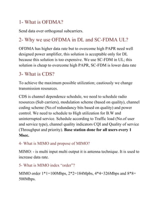
- OFDMA is used for downlink and SC-FDMA is used for uplink to overcome high PAPR issues.
- CDS dynamically schedules radio resources, modulation, coding and power control based on channel quality and traffic load.
- MIMO uses multiple antennas to increase data rates up to a maximum of 8x8 MIMO.
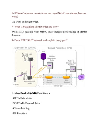
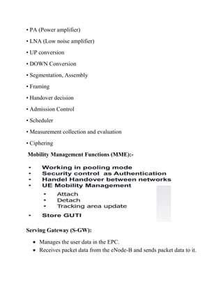
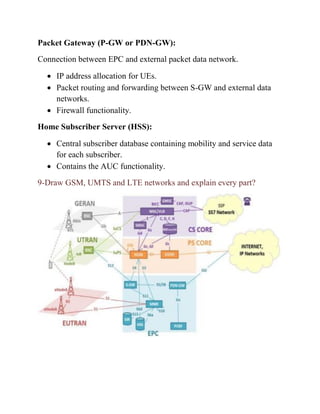
- The LTE network architecture includes the eNB, MME, S-GW and P-GW connected by various interfaces like S1, S6a, S5 etc.
- Security in LTE is based on