This document provides an overview of network drive testing on 2G/3G networks. It discusses the reasons for performing drive tests, including network performance monitoring, maintenance, benchmarking, and addressing customer complaints. It then outlines the modules to be covered in the training, including an overview of 3G systems, drive test concepts, performing outdoor drive tests, and drive test reporting and analysis. Key topics that will be covered include 3G/UMTS architectures, channelization, handover processes, and the parameters measured during 2G and 3G drive tests.
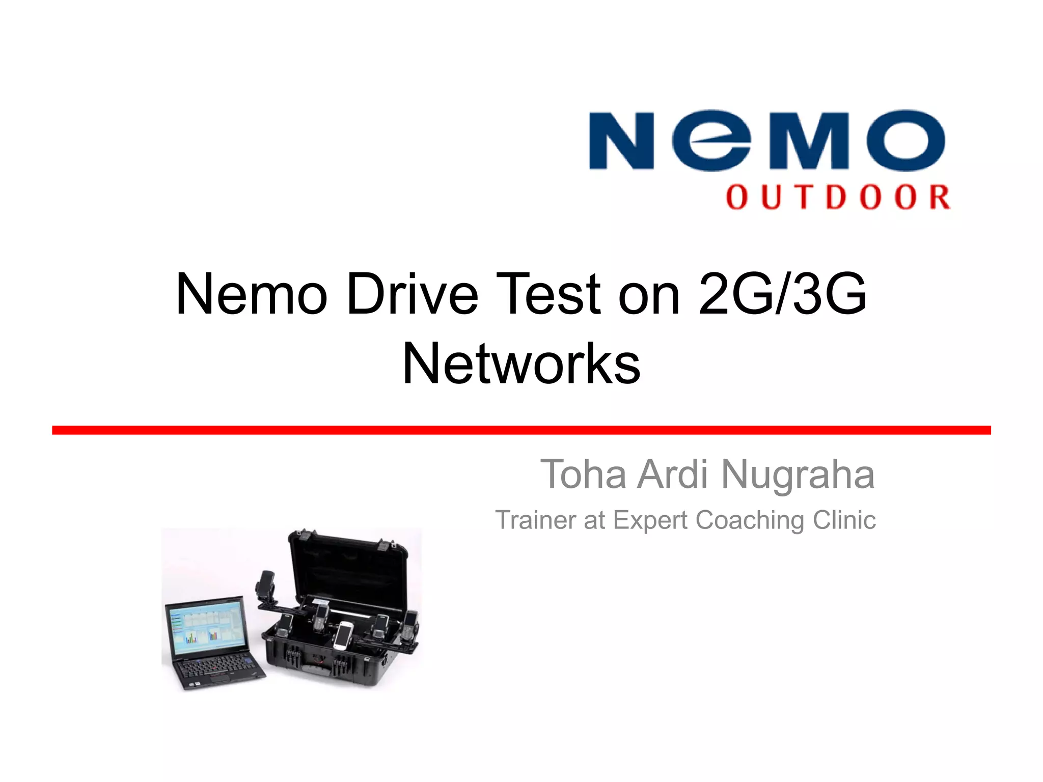
Introduction to Nemo Drive Test on 2G/3G networks by Toha Ardi Nugraha, Trainer.
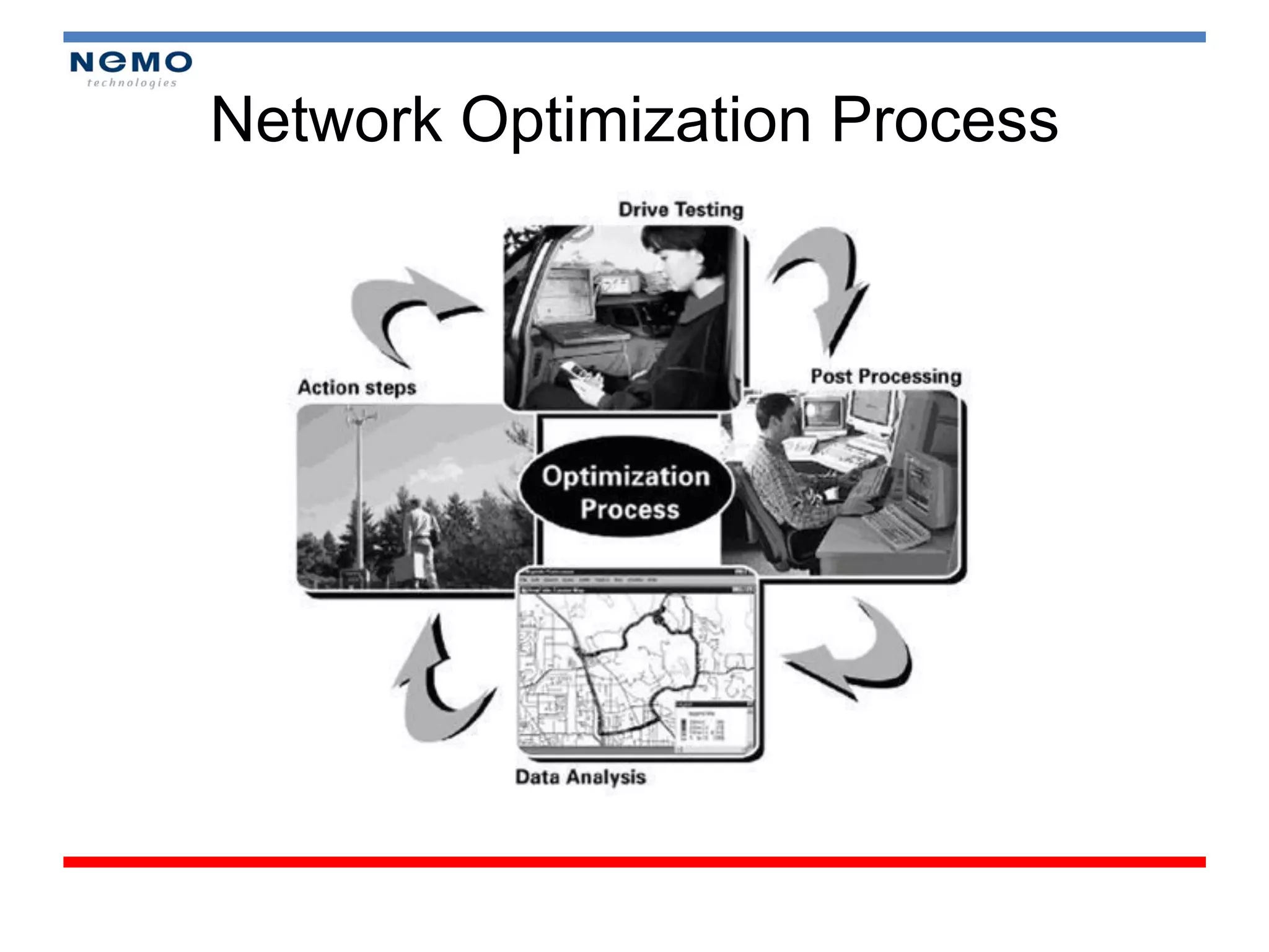
Introduction to Network Optimization Process with an emphasis on methodologies utilized.
Drive Tests are crucial for Network Performance Monitoring, Maintenance, Benchmarking, and addressing Customer Complaints.
Presentation of various modules in the training program for Drive Testing, covering topics like theory and fieldwork.
Introduction to Module 1: Overview of the 3G System and its components.
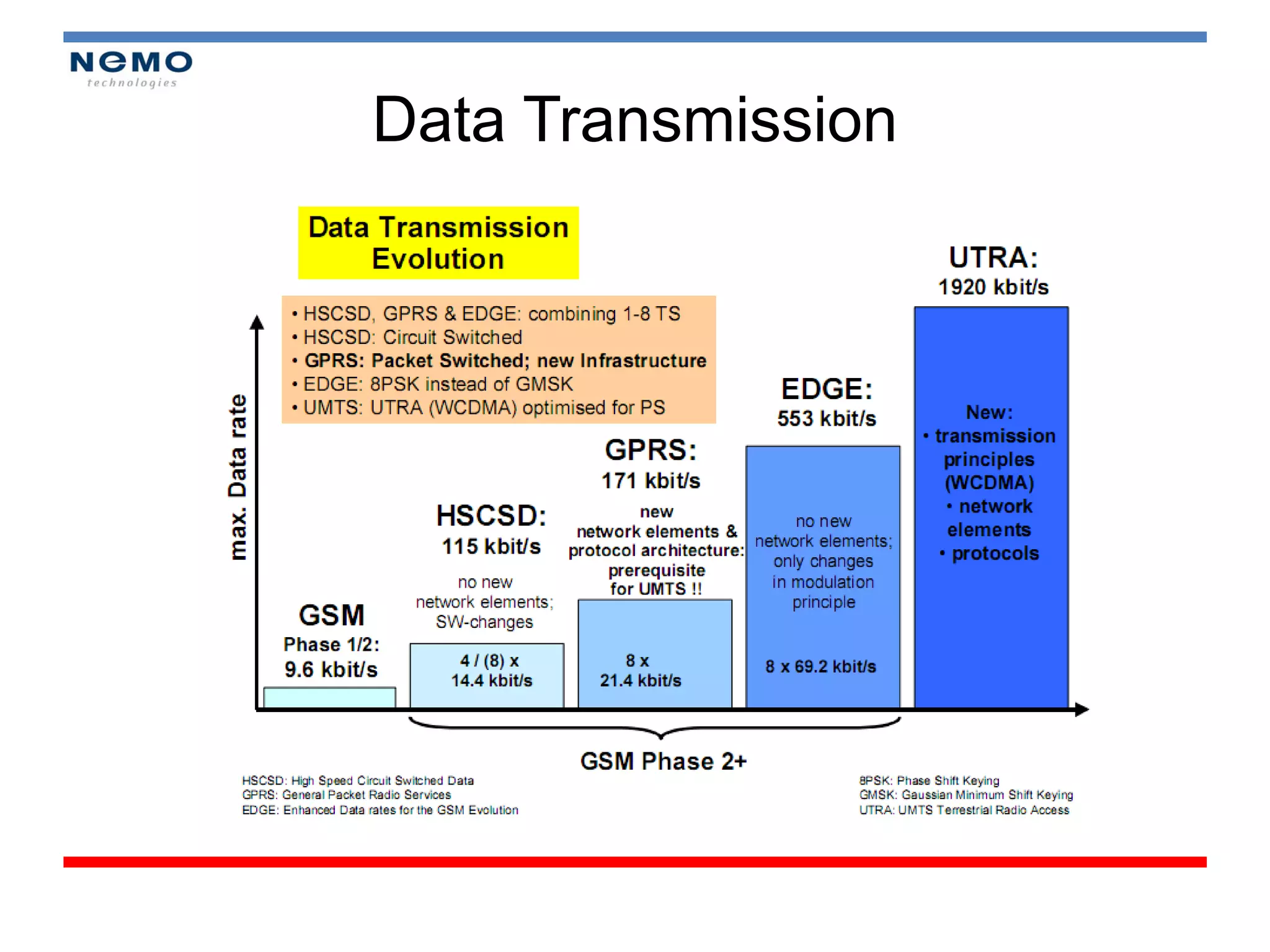
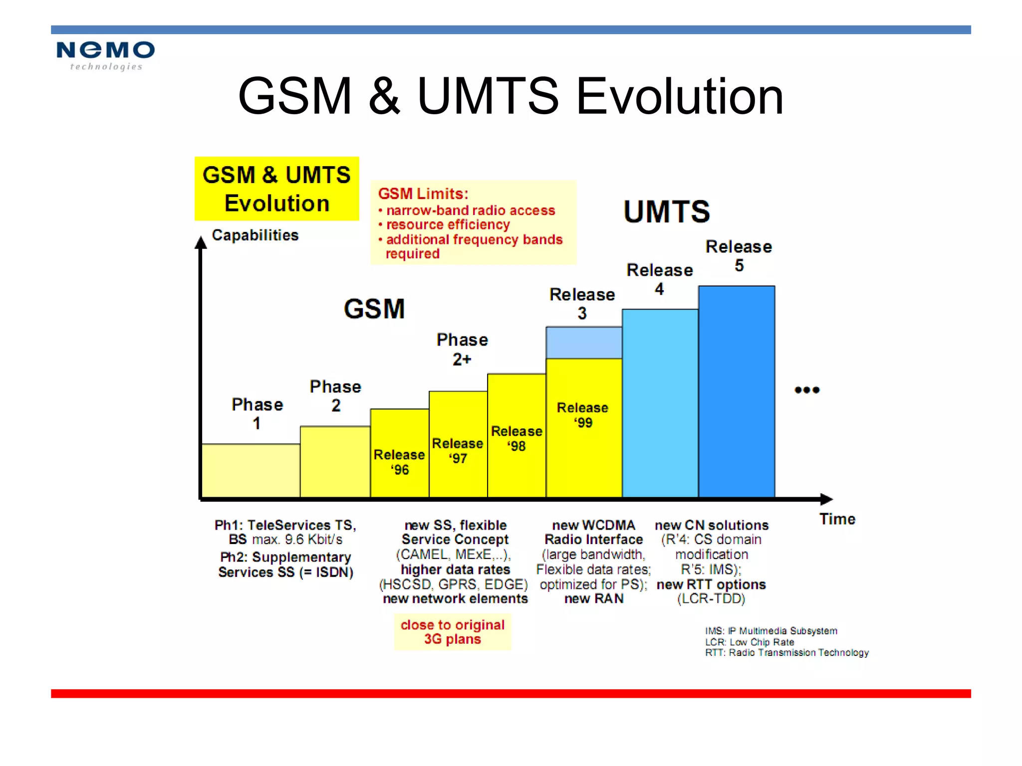
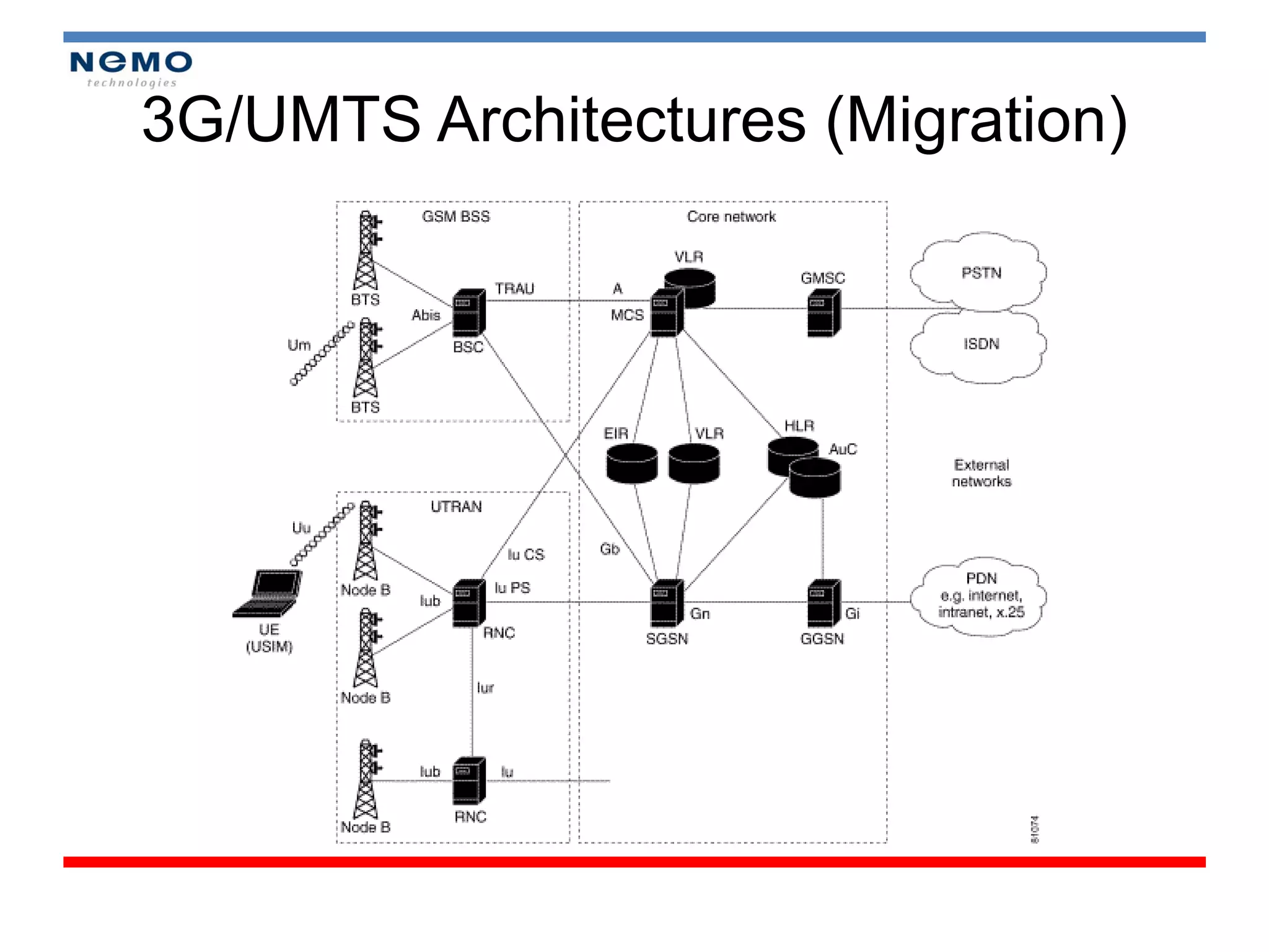
Explanation of data transmission technologies including GSM evolution and 3G/UMTS architectures.
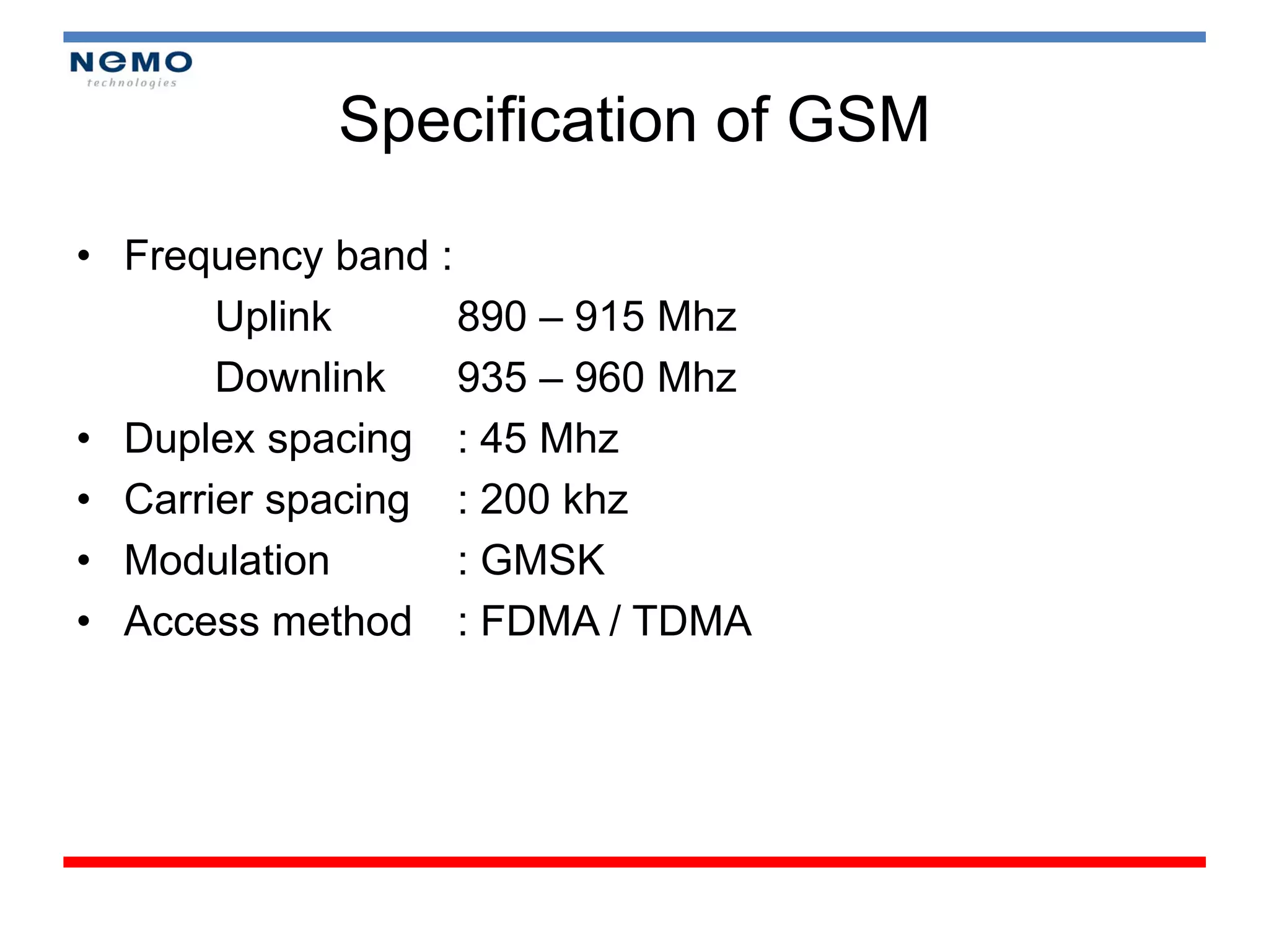
Detailed specifications and architecture of GSM networks, including frequency bands and subsystems.
Overview of GSM frequency bands and the channelization methods including physical and logical channels.
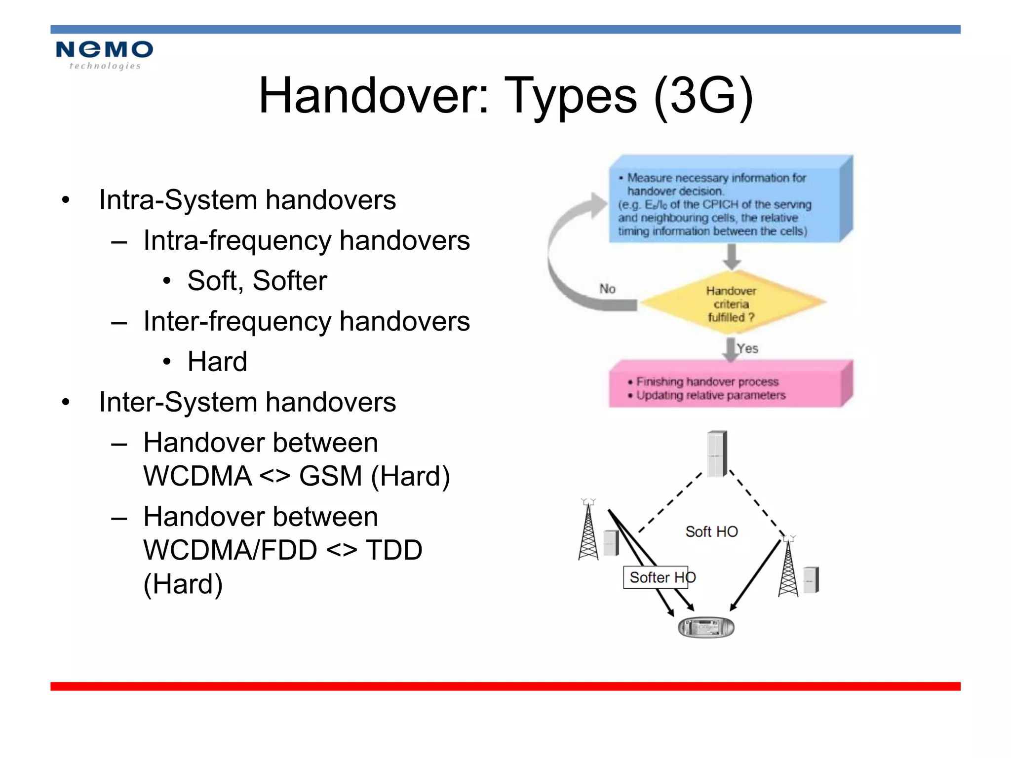
Explains the concepts of WCDMA, UMTS architecture, channelization methods, and handover processes.
Description of handover types in both 2G and 3G networks with respect to mobility management.
Defines pilot sets used for handover decisions and describes soft handover algorithms.
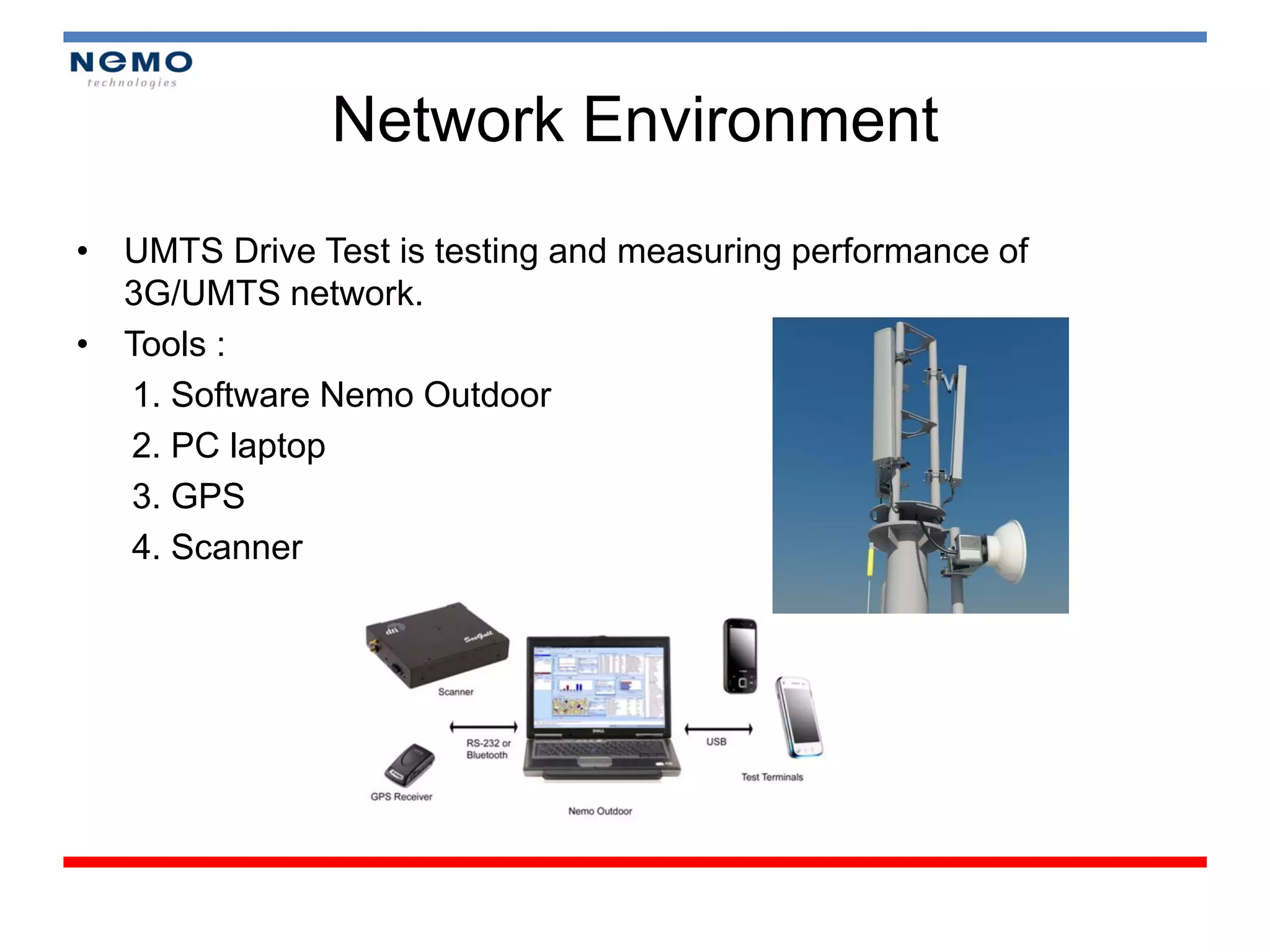
Details of tools used for drive tests, including software and devices, along with setup instructions. Instructions on accessing Device Manager and connecting devices for proper measurement.
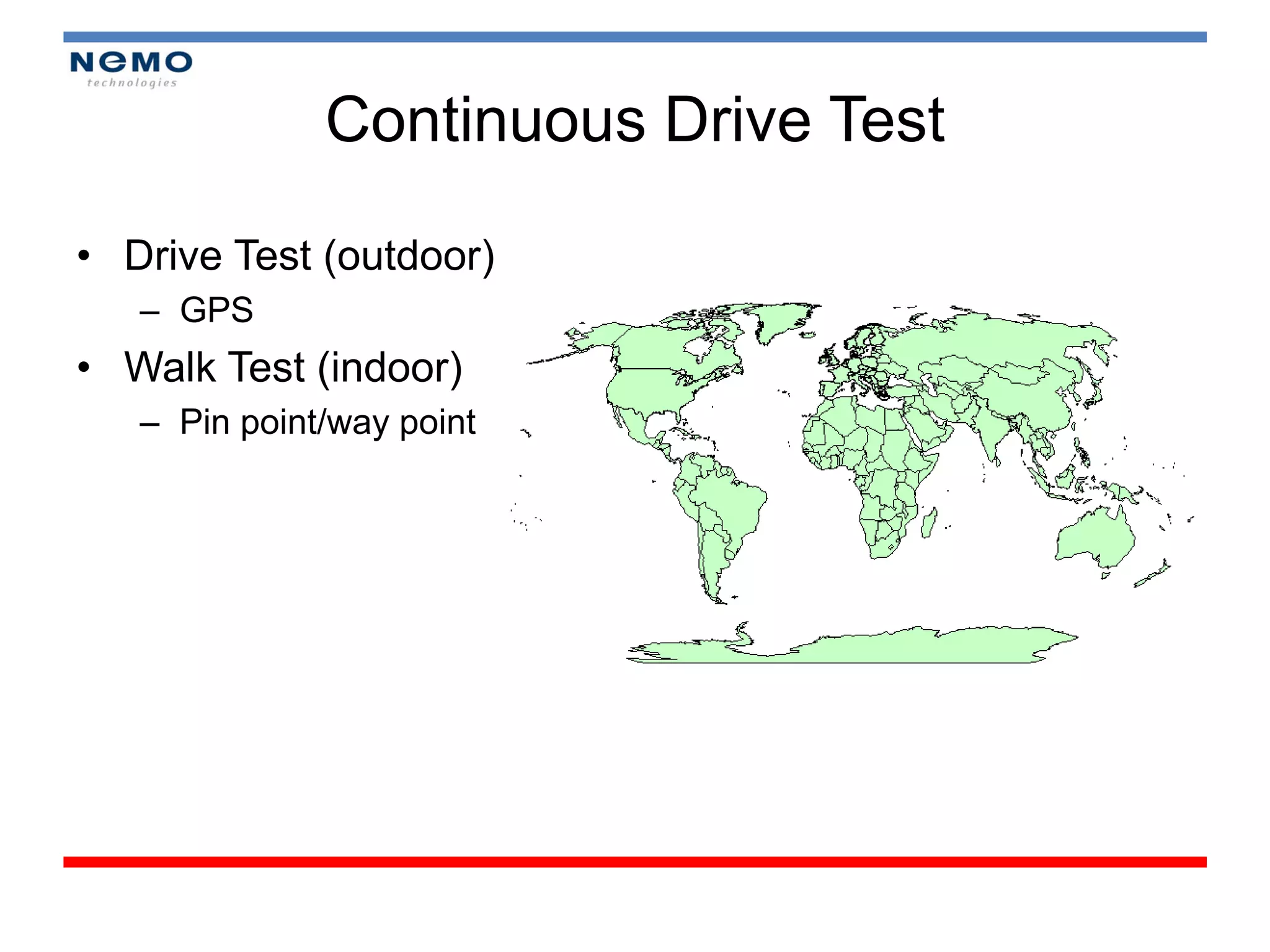
Module 3: Execution of Drive Tests in an outdoor setting.
Module 4 introduces the importance of reporting in network analysis along with map usage.
Detailing the use of KPIs for network performance assessment including RSCP, Ec/No.
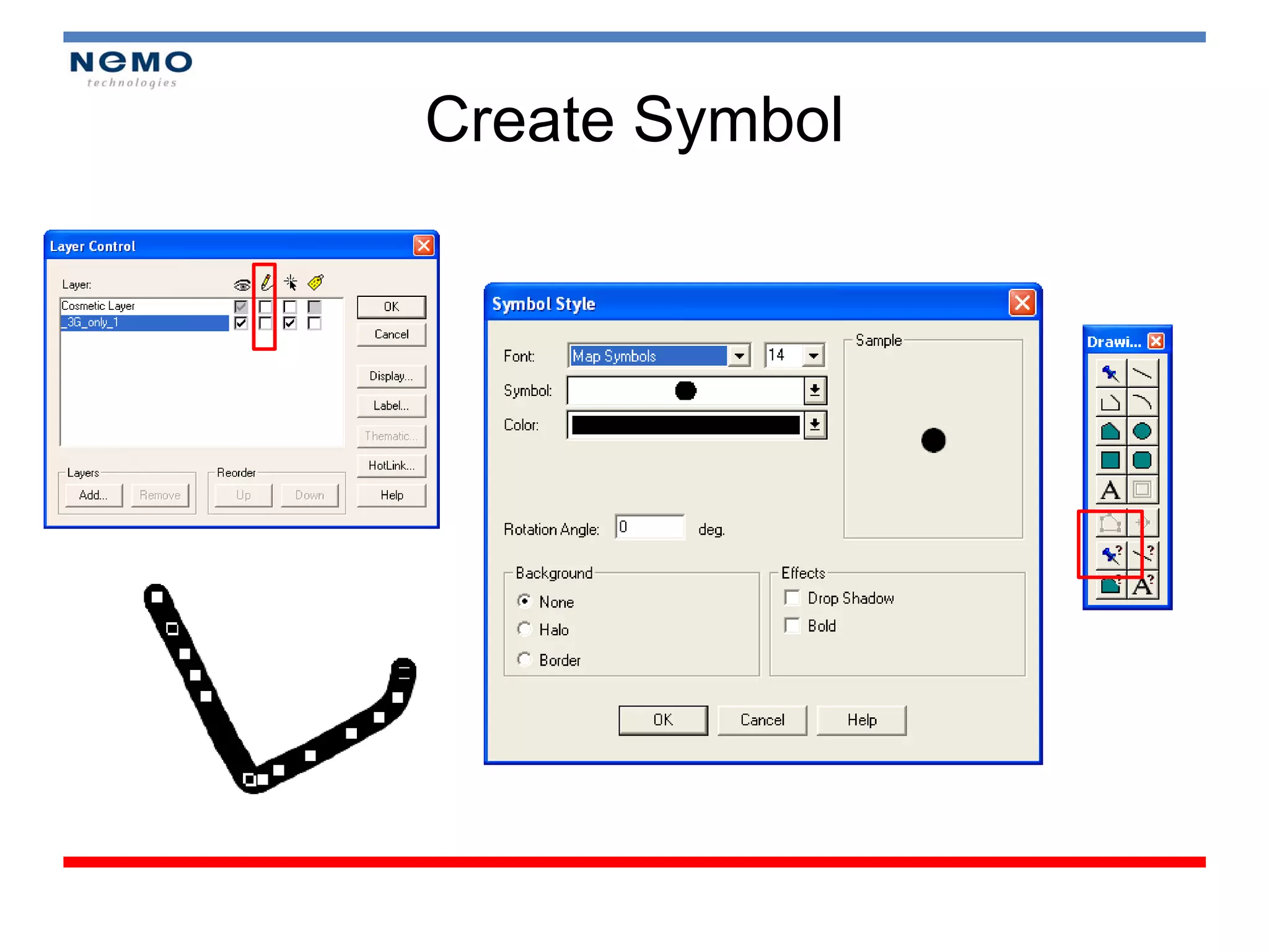
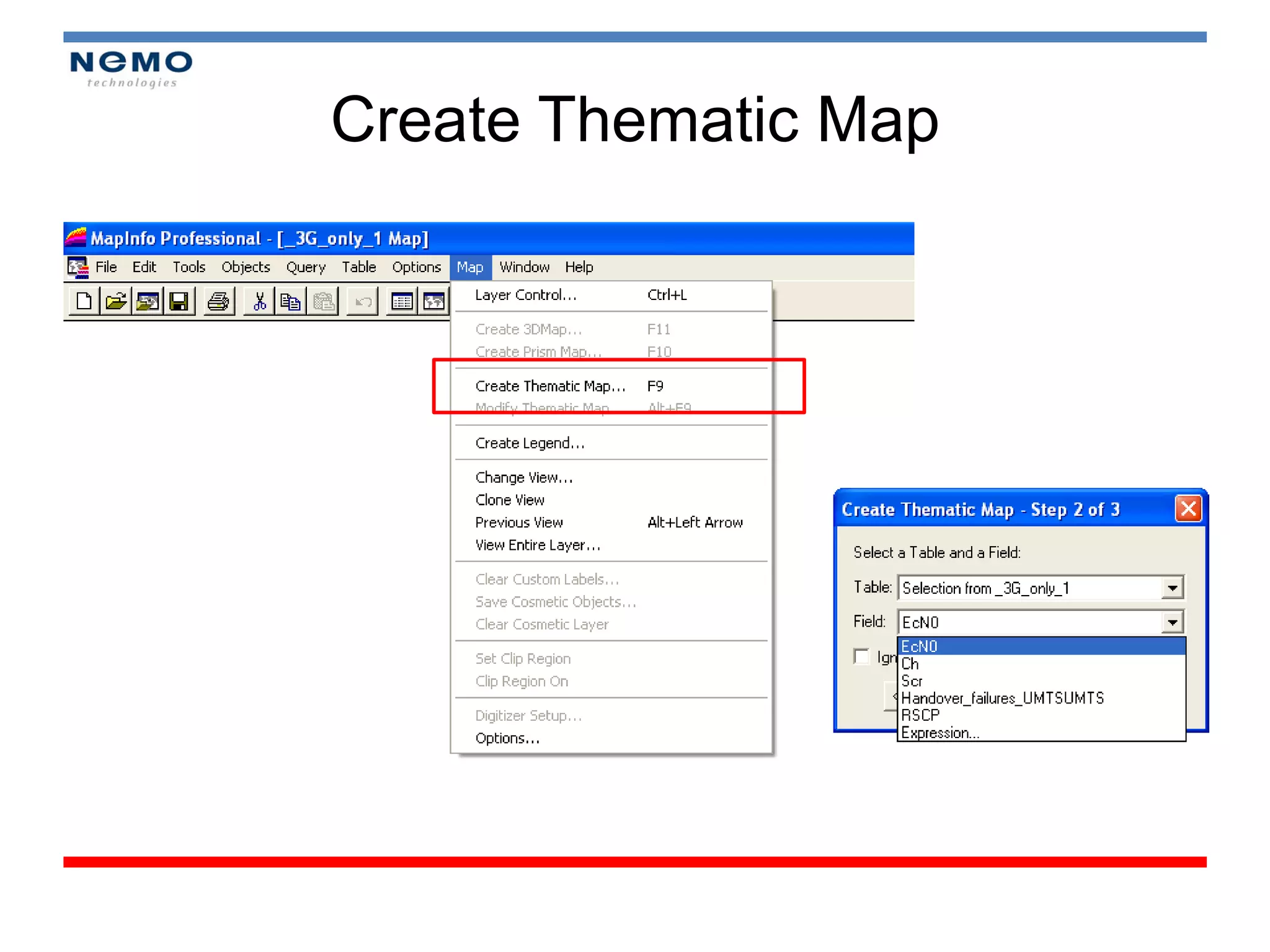
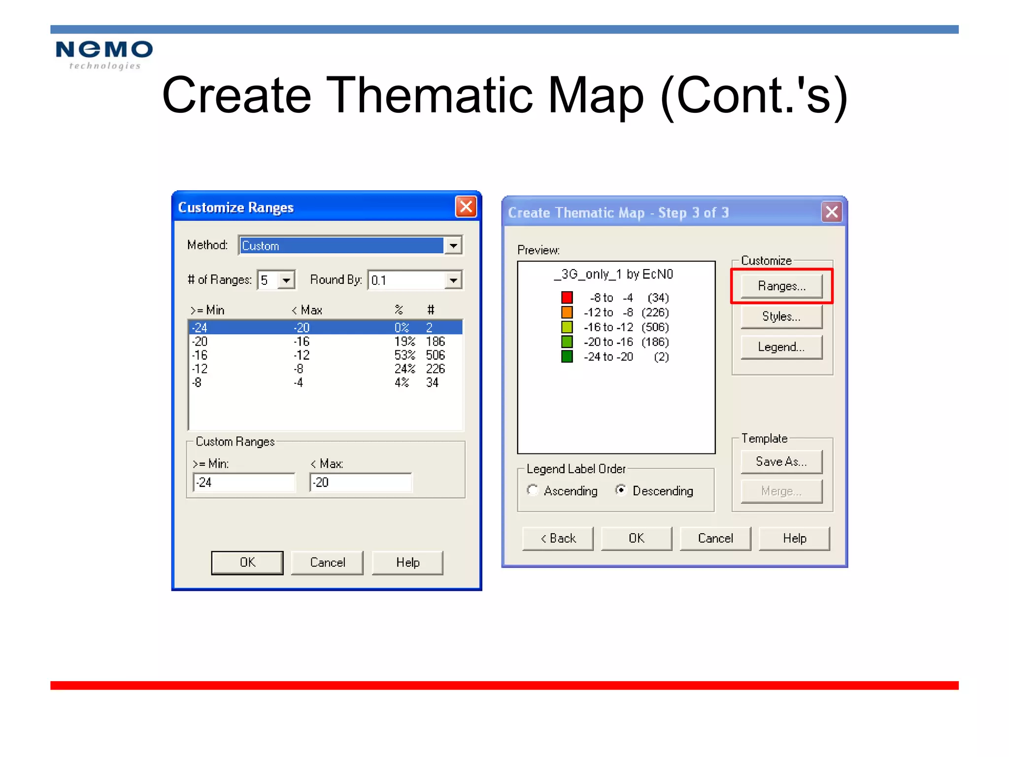
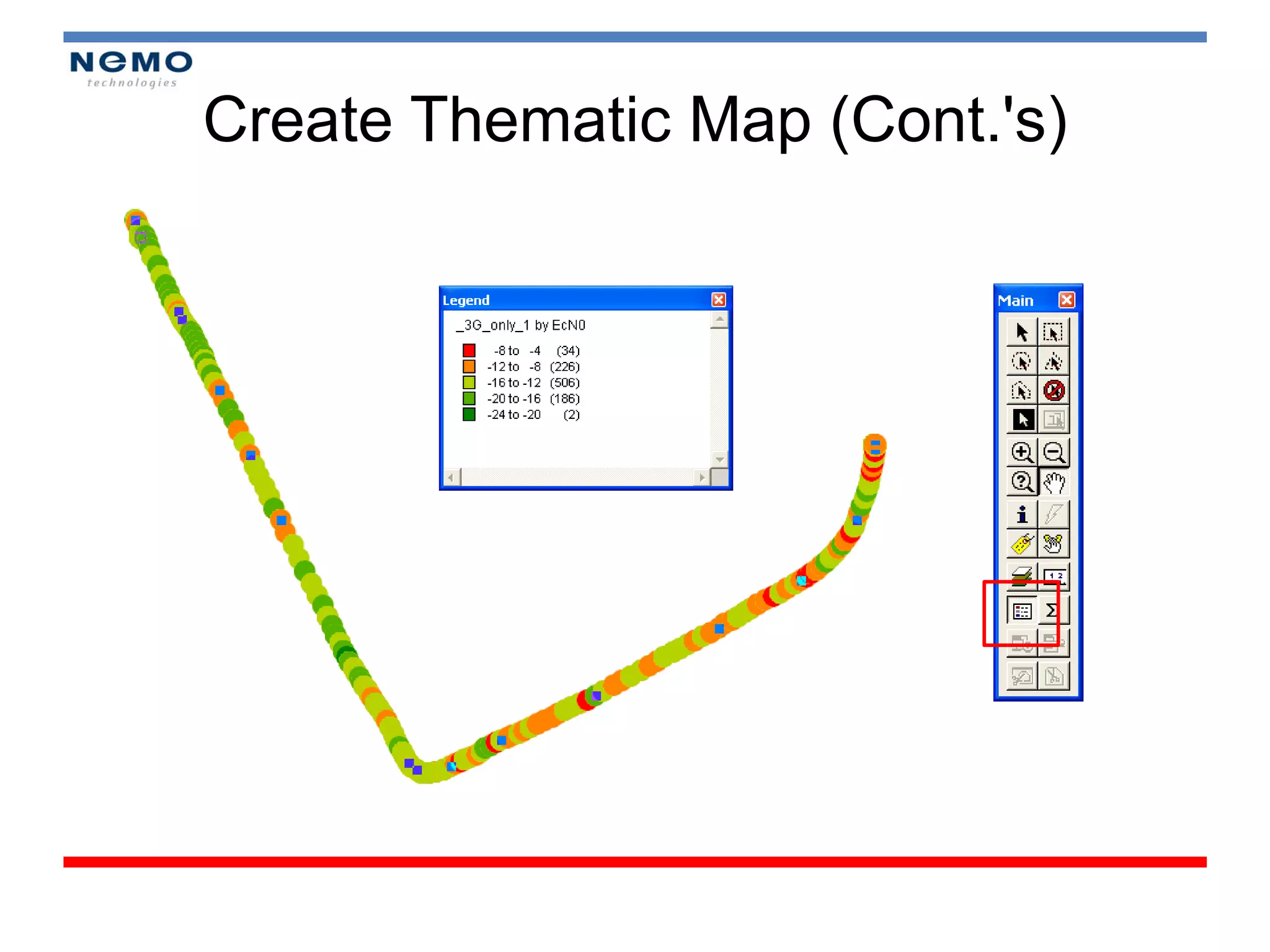
Creating thematic maps and utilizing layer control for enhanced network reporting.
Enter Module 4 focusing on network tuning, performance indicators, and enhancing coverage strategies.Discusses antenna types and optimization techniques to enhance network performance.
Citations of courses and acknowledgments for the training material provided.
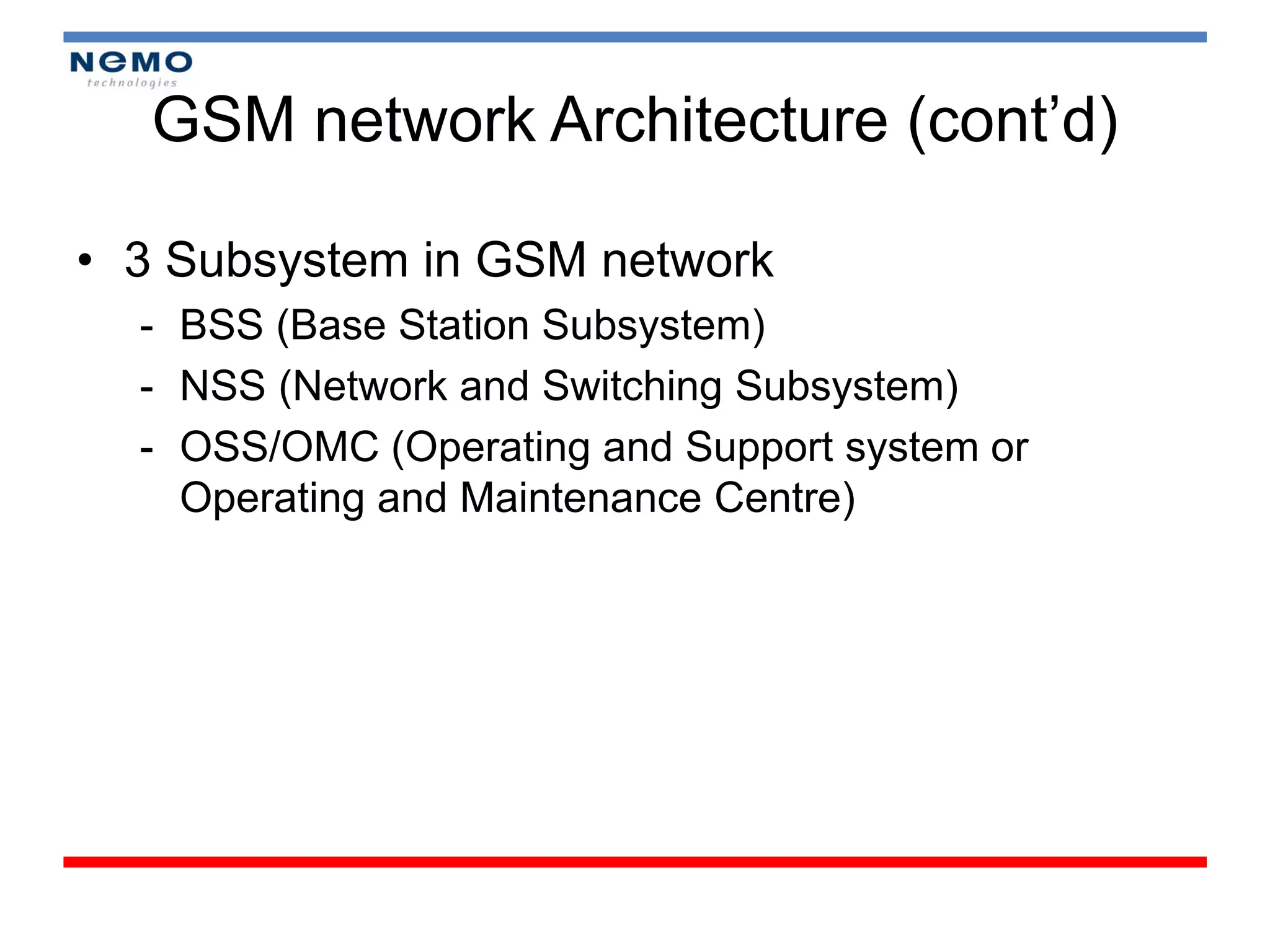
GSM network Architecture(cont’d)
• 3 Subsystem in GSM network
- BSS (Base Station Subsystem)
- NSS (Network and Switching Subsystem)
- OSS/OMC (Operating and Support system or
Operating and Maintenance Centre)
11.
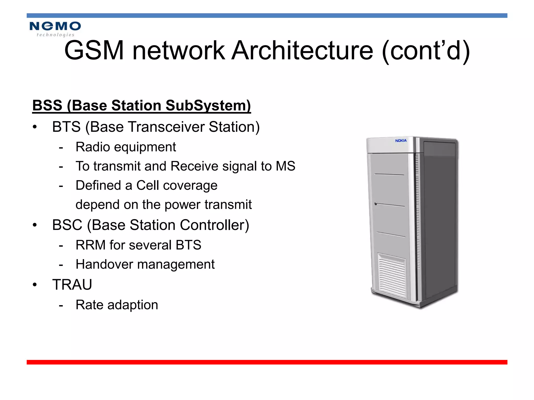
GSM network Architecture(cont’d)
BSS (Base Station SubSystem)
• BTS (Base Transceiver Station)
- Radio equipment
- To transmit and Receive signal to MS
- Defined a Cell coverage
depend on the power transmit
• BSC (Base Station Controller)
- RRM for several BTS
- Handover management
• TRAU
- Rate adaption
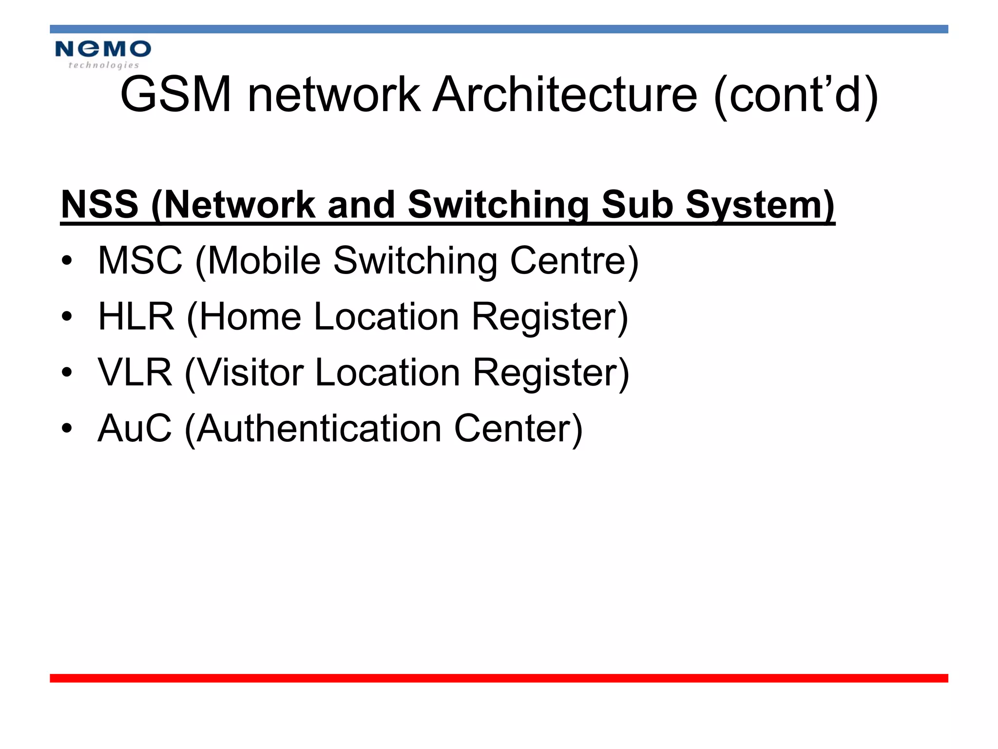
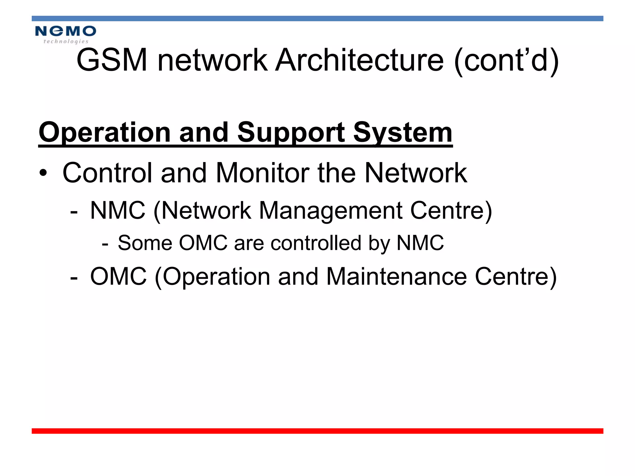
GSM network Architecture(cont’d)
Operation and Support System
• Control and Monitor the Network
- NMC (Network Management Centre)
- Some OMC are controlled by NMC
- OMC (Operation and Maintenance Centre)
14.
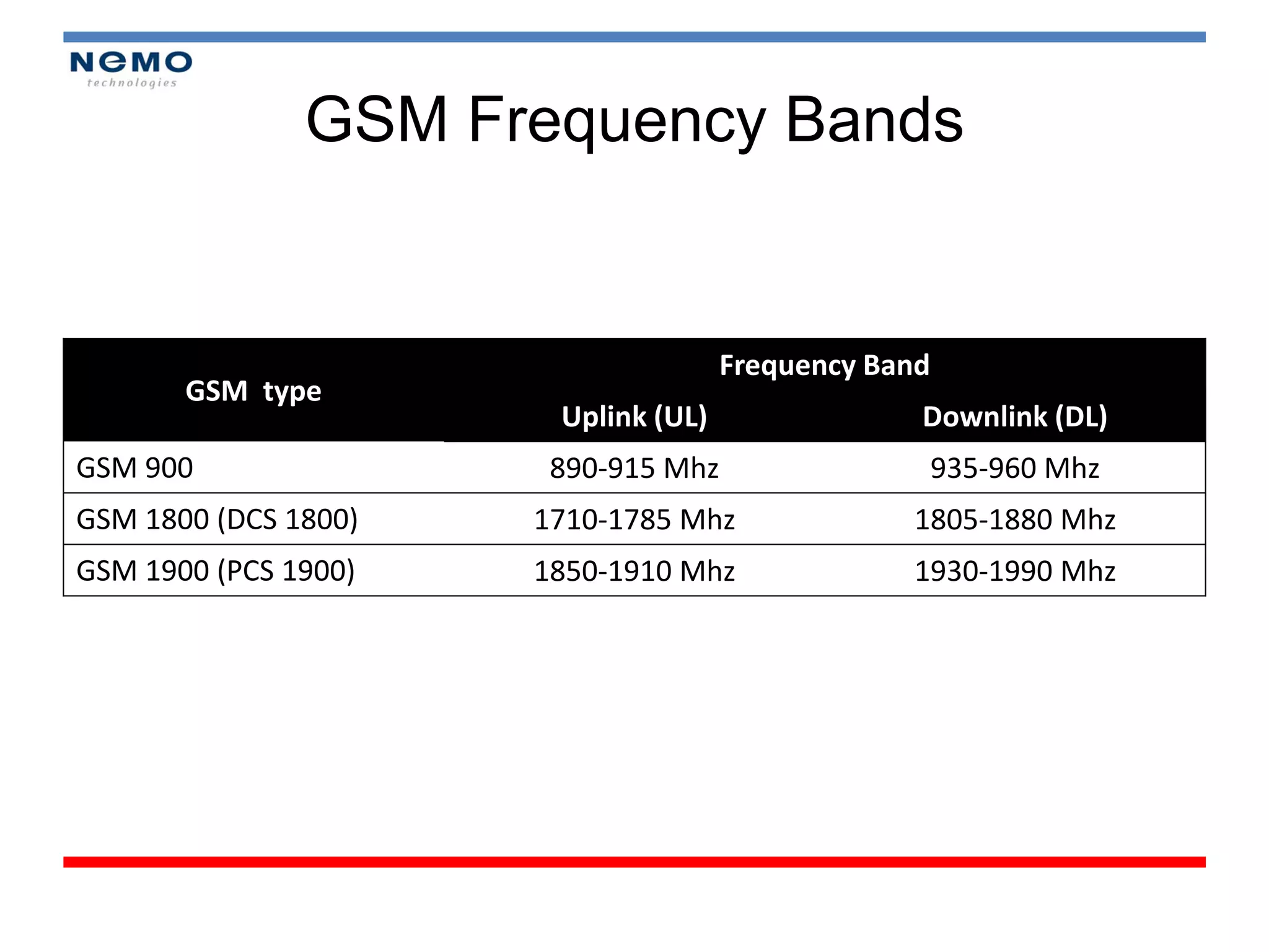
GSM Frequency Bands
Frequency Band
GSM type
Uplink (UL) Downlink (DL)
GSM 900 890-915 Mhz 935-960 Mhz
GSM 1800 (DCS 1800) 1710-1785 Mhz 1805-1880 Mhz
GSM 1900 (PCS 1900) 1850-1910 Mhz 1930-1990 Mhz
15.
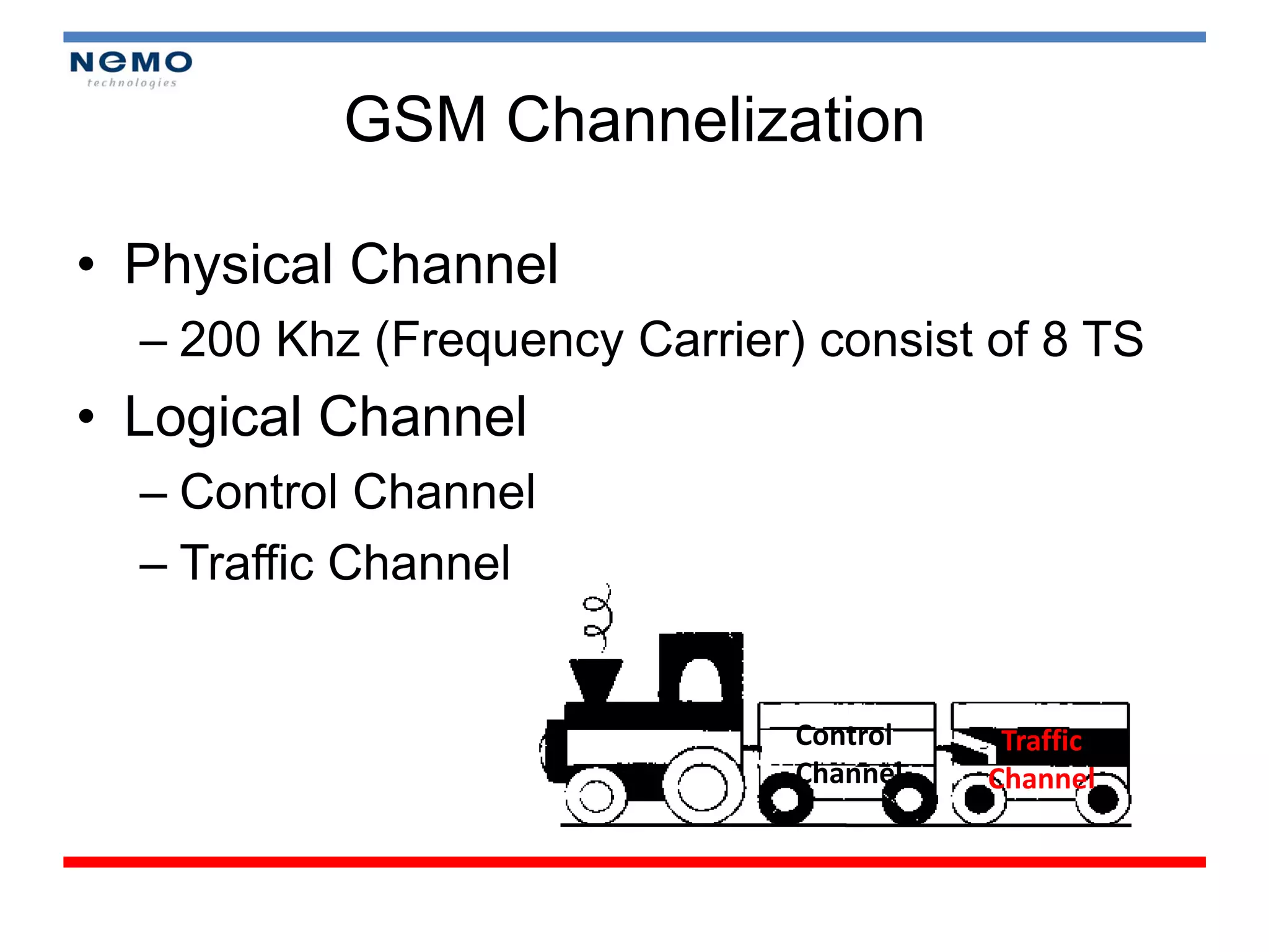
GSM Channelization
• PhysicalChannel
– 200 Khz (Frequency Carrier) consist of 8 TS
• Logical Channel
– Control Channel
– Traffic Channel
Control Traffic
Channel Channel
16.
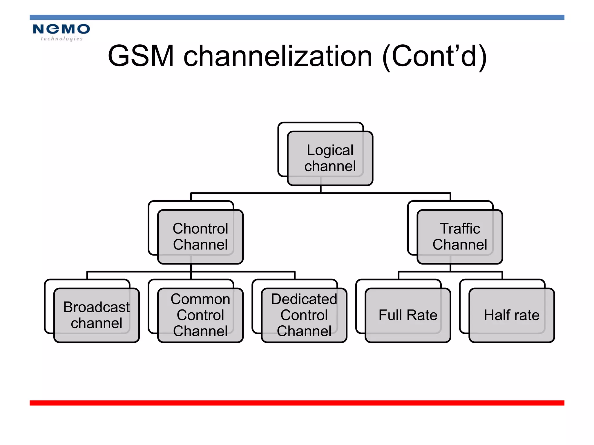
GSM channelization (Cont’d)
Logical
channel
Chontrol Traffic
Channel Channel
Common Dedicated
Broadcast
Control Control Full Rate Half rate
channel
Channel Channel
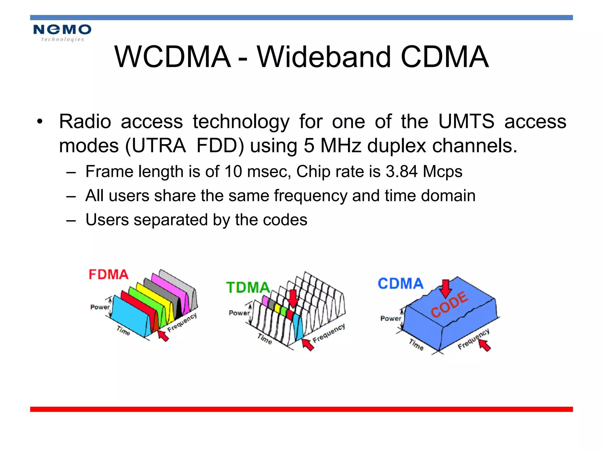
WCDMA - WidebandCDMA
• Radio access technology for one of the UMTS access
modes (UTRA FDD) using 5 MHz duplex channels.
– Frame length is of 10 msec, Chip rate is 3.84 Mcps
– All users share the same frequency and time domain
– Users separated by the codes
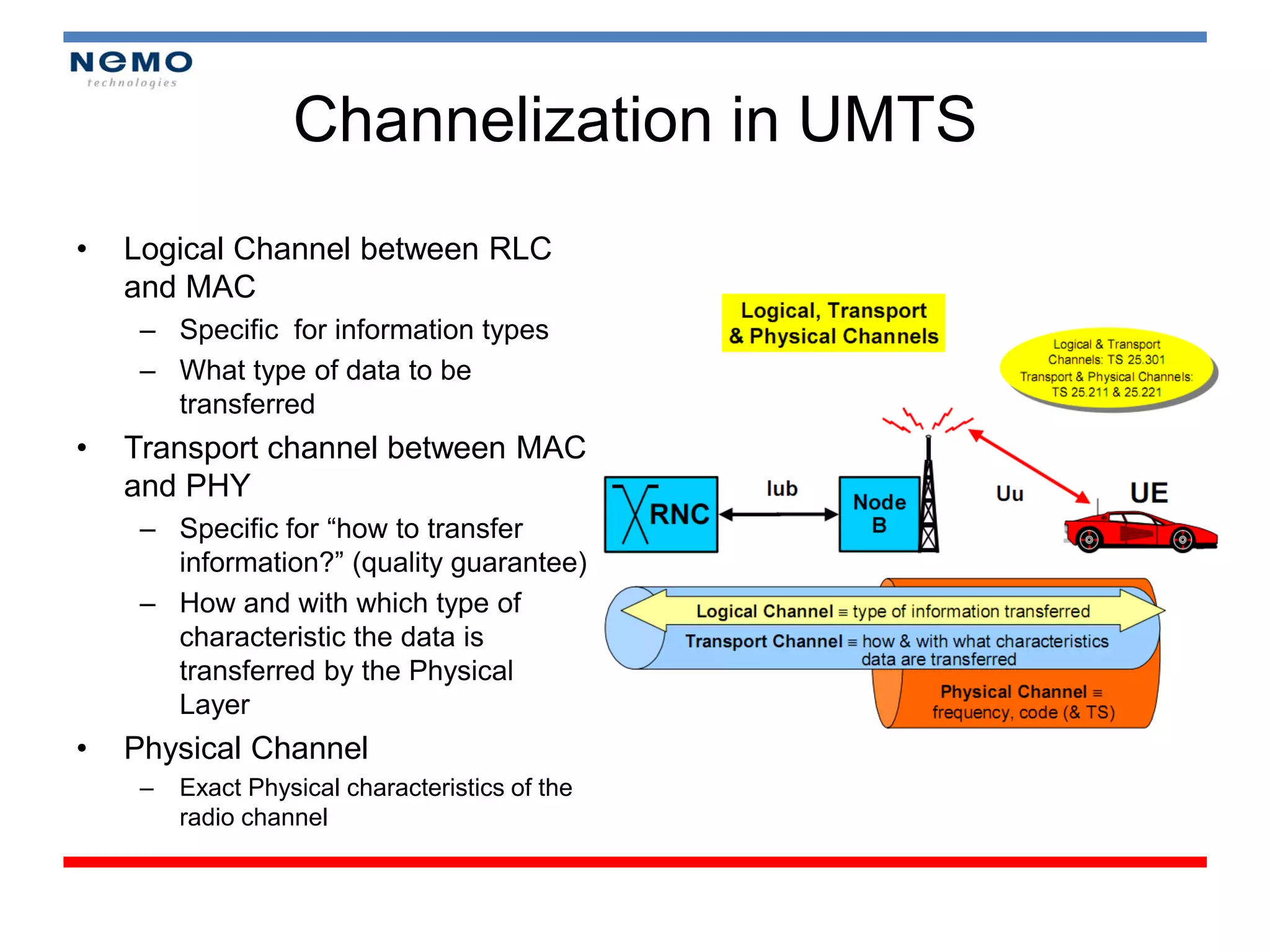
Channelization in UMTS
• Logical Channel between RLC
and MAC
– Specific for information types
– What type of data to be
transferred
• Transport channel between MAC
and PHY
– Specific for “how to transfer
information?” (quality guarantee)
– How and with which type of
characteristic the data is
transferred by the Physical
Layer
• Physical Channel
– Exact Physical characteristics of the
radio channel
21.
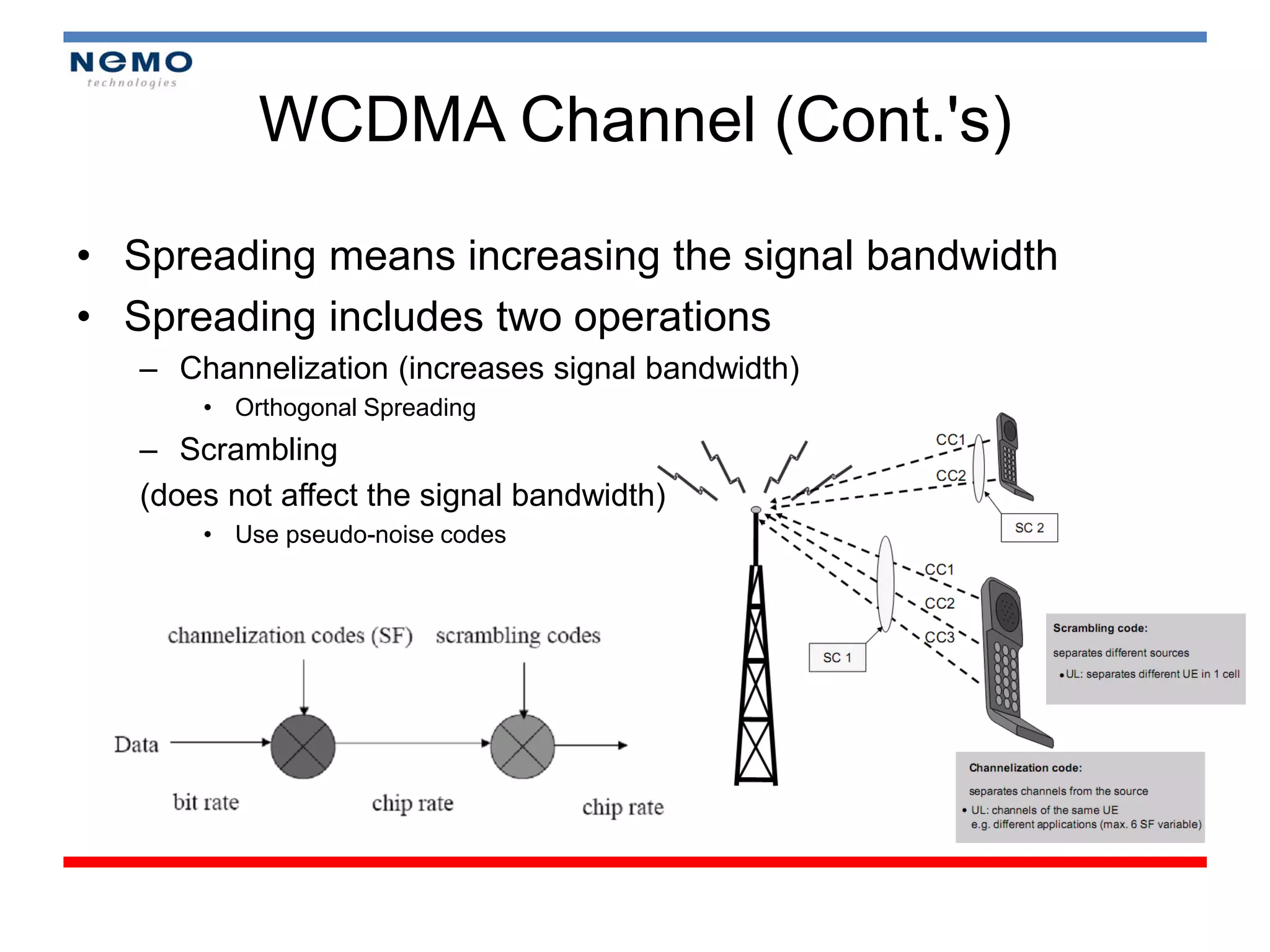
WCDMA Channel (Cont.'s)
•Spreading means increasing the signal bandwidth
• Spreading includes two operations
– Channelization (increases signal bandwidth)
• Orthogonal Spreading
– Scrambling
(does not affect the signal bandwidth)
• Use pseudo-noise codes
22.
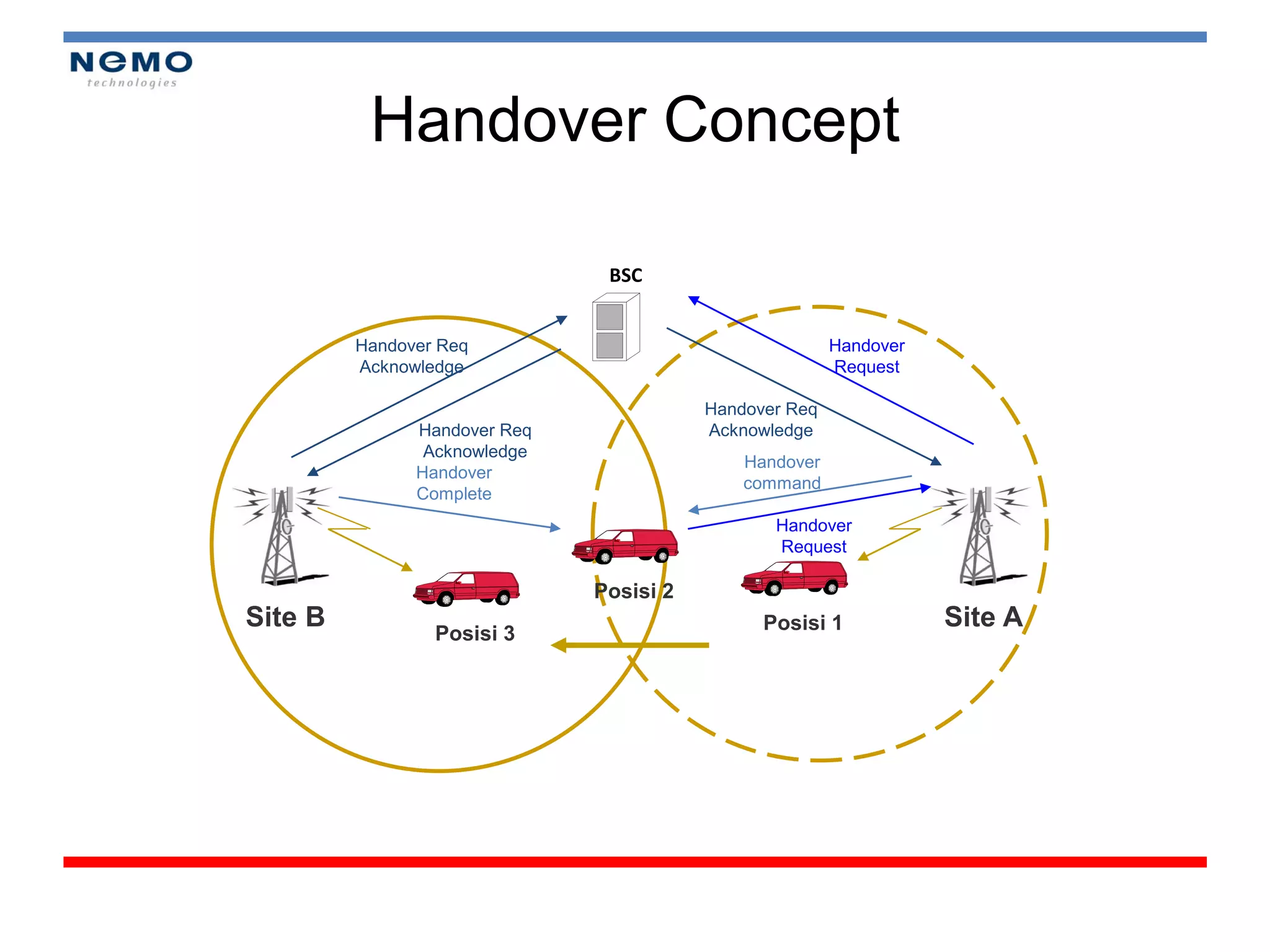
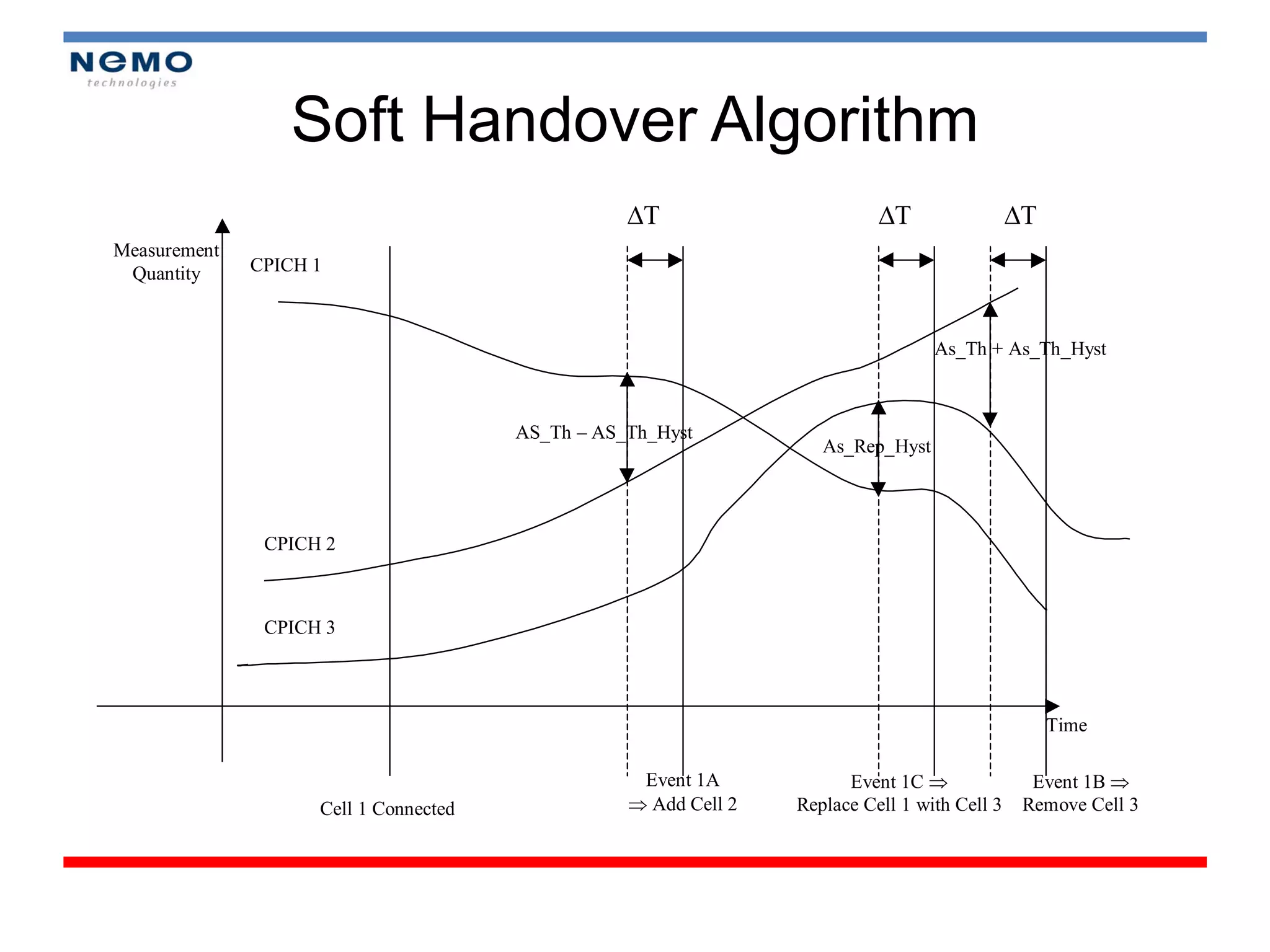
Handover Concept
BSC
Handover Req Handover
Acknowledge Request
Handover Req
Handover Req Acknowledge
Acknowledge
Handover
Handover
command
Complete
Handover
Request
Posisi 2
Site B Posisi 1 Site A
Posisi 3
23.
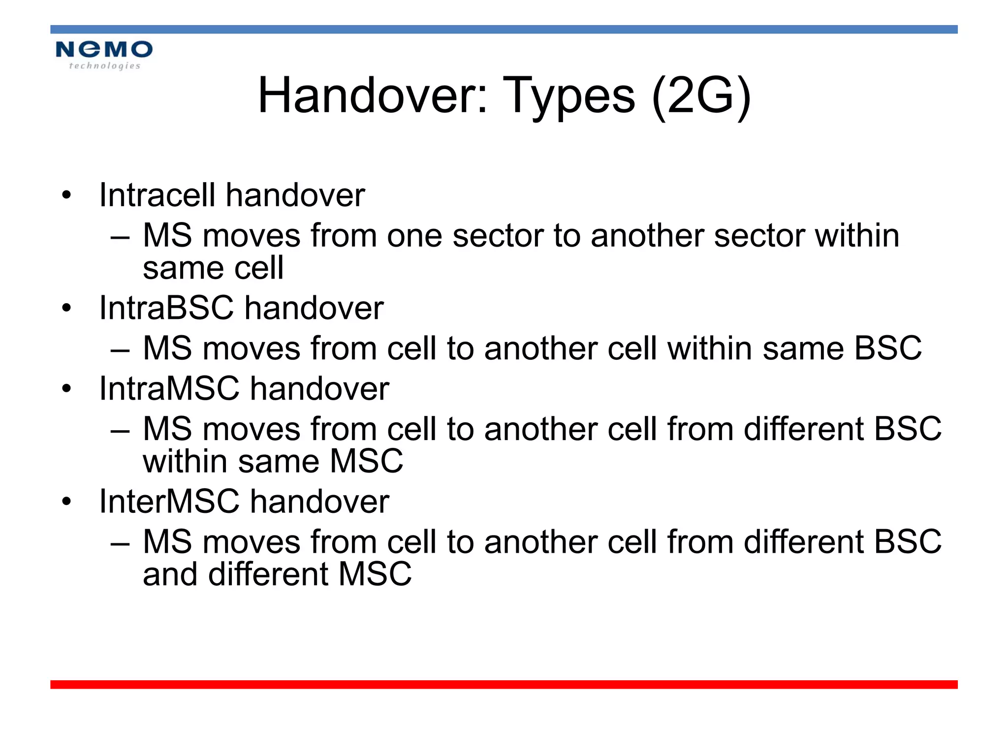
Handover: Types (2G)
•Intracell handover
– MS moves from one sector to another sector within
same cell
• IntraBSC handover
– MS moves from cell to another cell within same BSC
• IntraMSC handover
– MS moves from cell to another cell from different BSC
within same MSC
• InterMSC handover
– MS moves from cell to another cell from different BSC
and different MSC
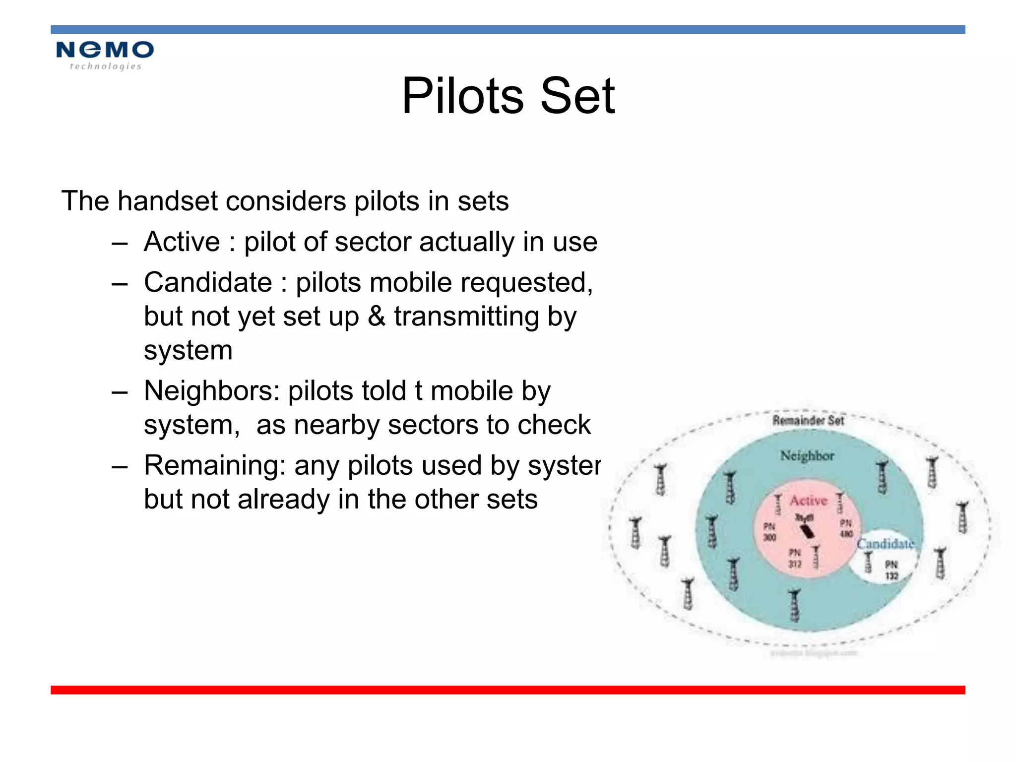
Pilots Set
The handsetconsiders pilots in sets
– Active : pilot of sector actually in use
– Candidate : pilots mobile requested,
but not yet set up & transmitting by
system
– Neighbors: pilots told t mobile by
system, as nearby sectors to check
– Remaining: any pilots used by system
but not already in the other sets
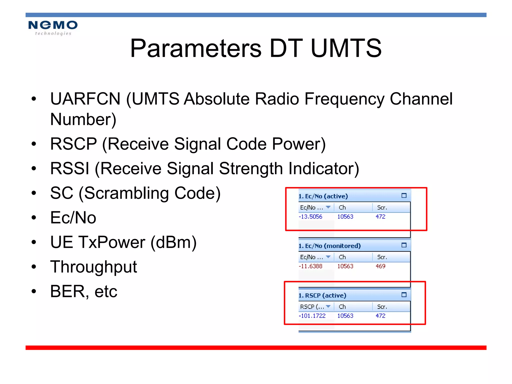
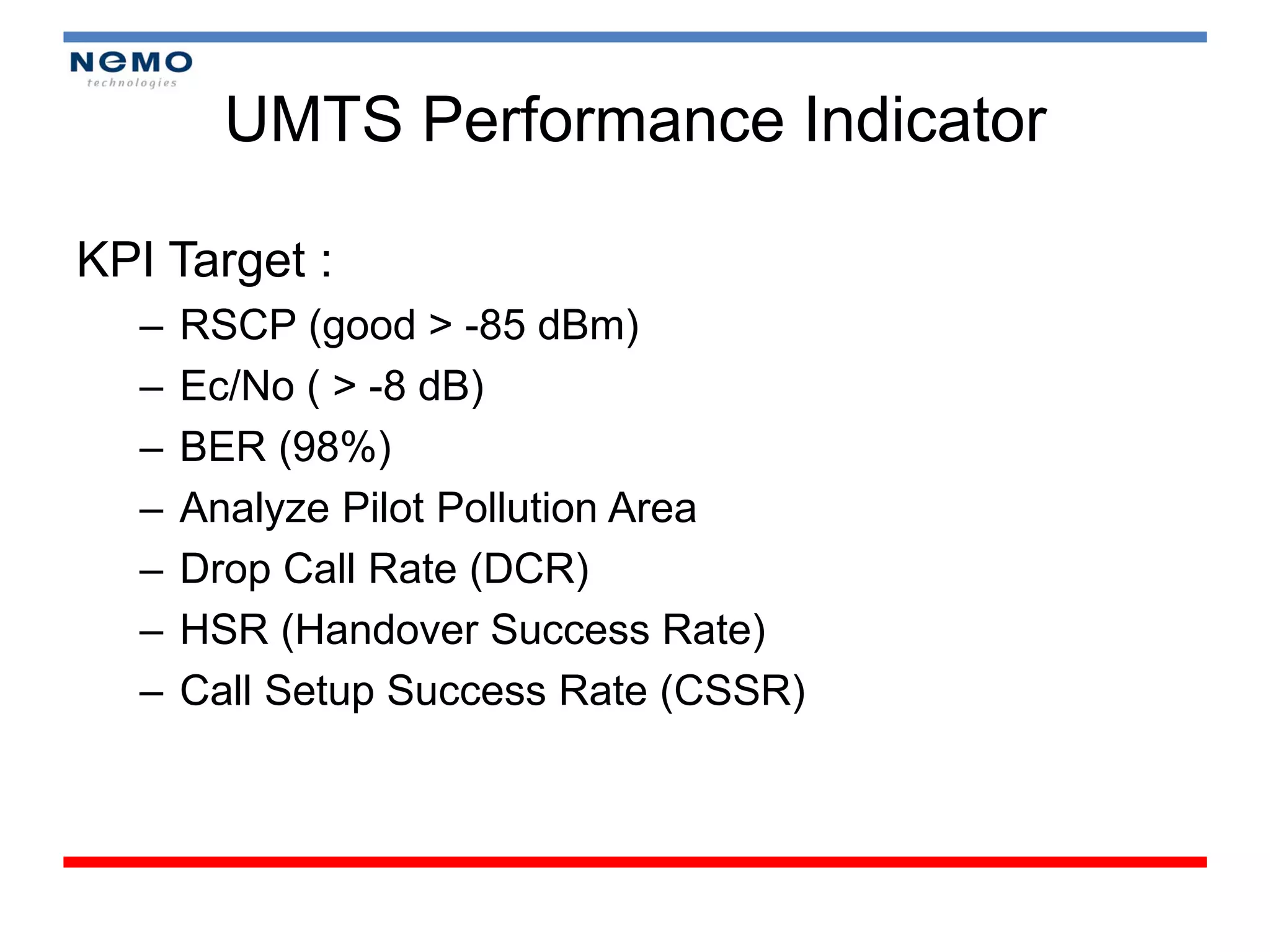
Parameters DT UMTS
•UARFCN (UMTS Absolute Radio Frequency Channel
Number)
• RSCP (Receive Signal Code Power)
• RSSI (Receive Signal Strength Indicator)
• SC (Scrambling Code)
• Ec/No
• UE TxPower (dBm)
• Throughput
• BER, etc
35.
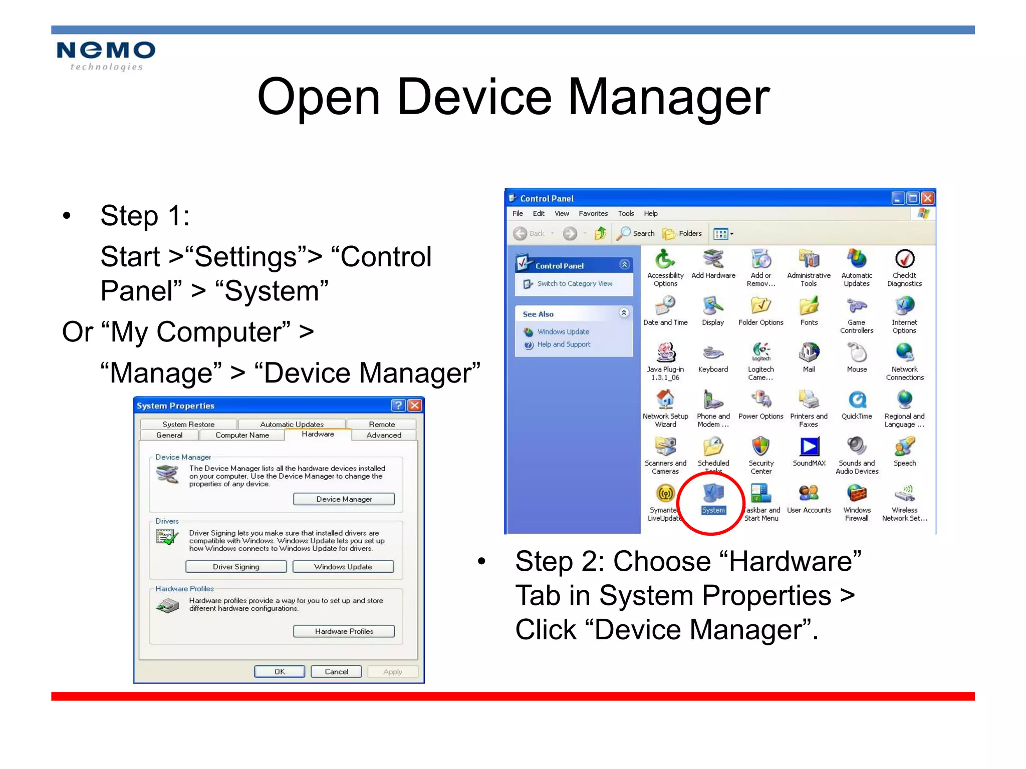
Open Device Manager
•Step 1:
Start >“Settings”> “Control
Panel” > “System”
Or “My Computer” >
“Manage” > “Device Manager”
• Step 2: Choose “Hardware”
Tab in System Properties >
Click “Device Manager”.
36.
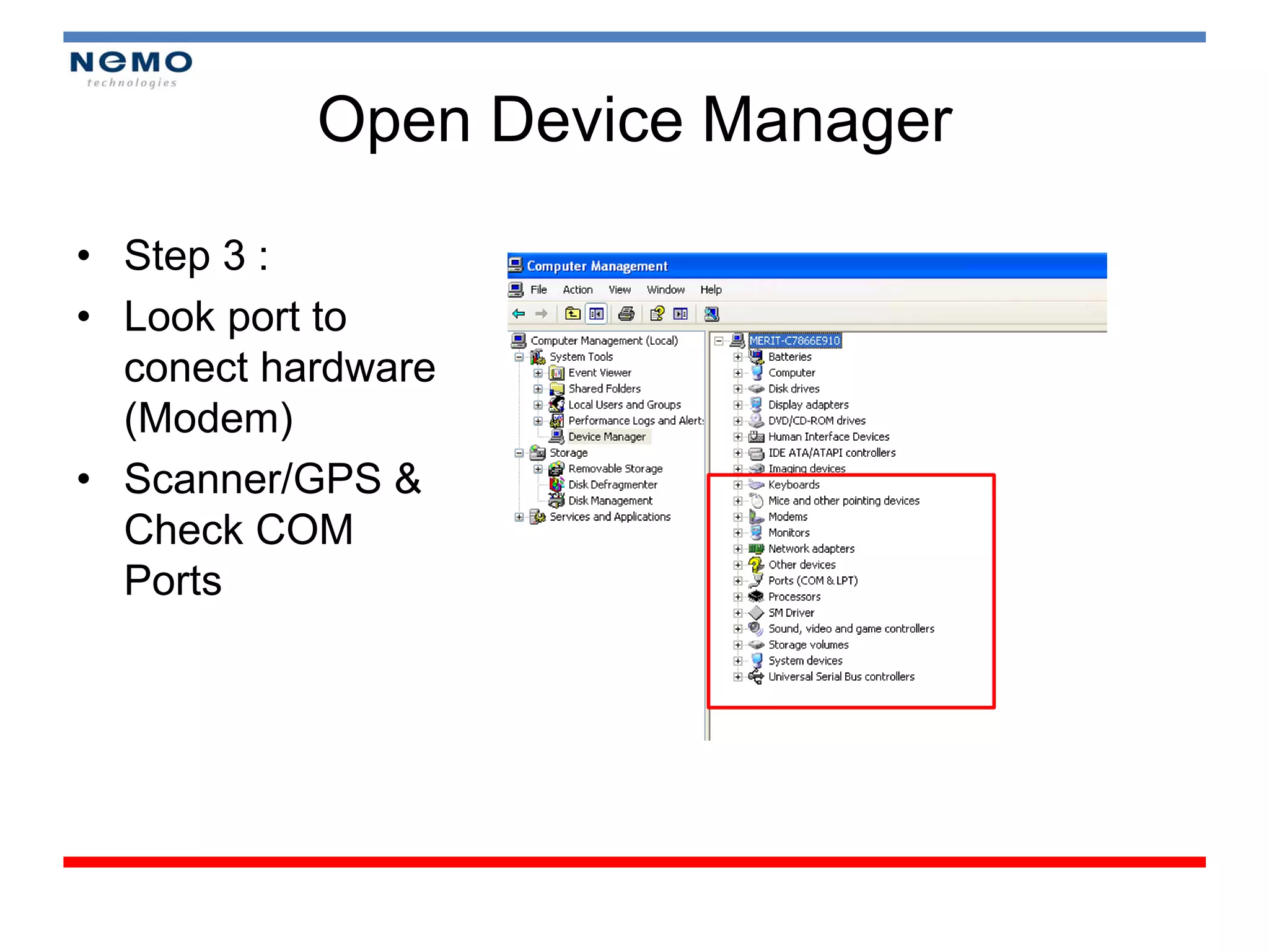
Open Device Manager
•Step 3 :
• Look port to
conect hardware
(Modem)
• Scanner/GPS &
Check COM
Ports
37.
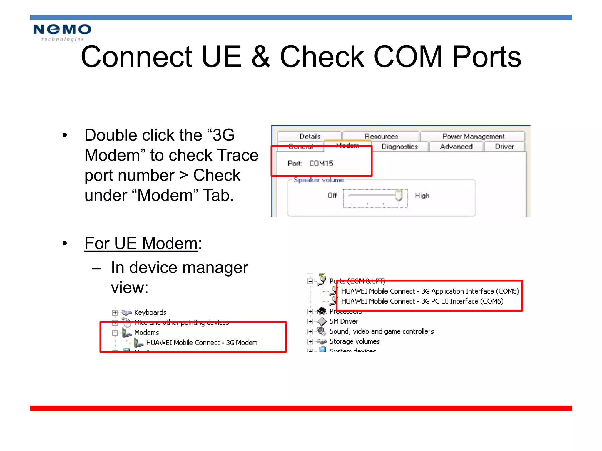
Connect UE &Check COM Ports
• Double click the “3G
Modem” to check Trace
port number > Check
under “Modem” Tab.
• For UE Modem:
– In device manager
view:
38.
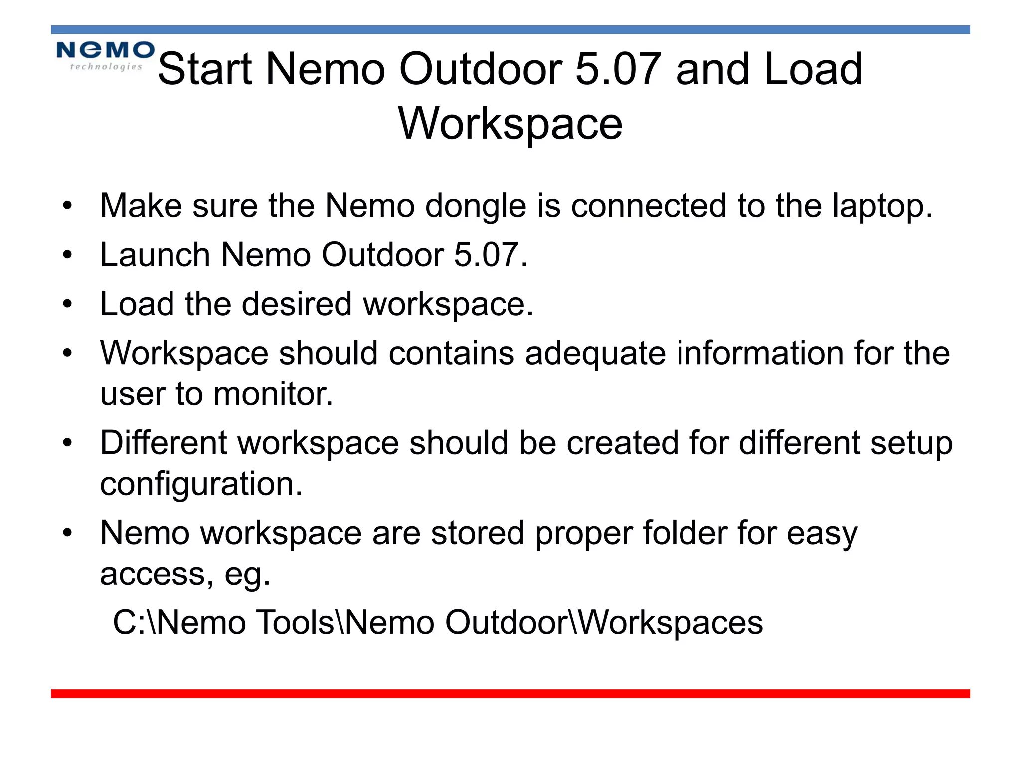
Start Nemo Outdoor5.07 and Load
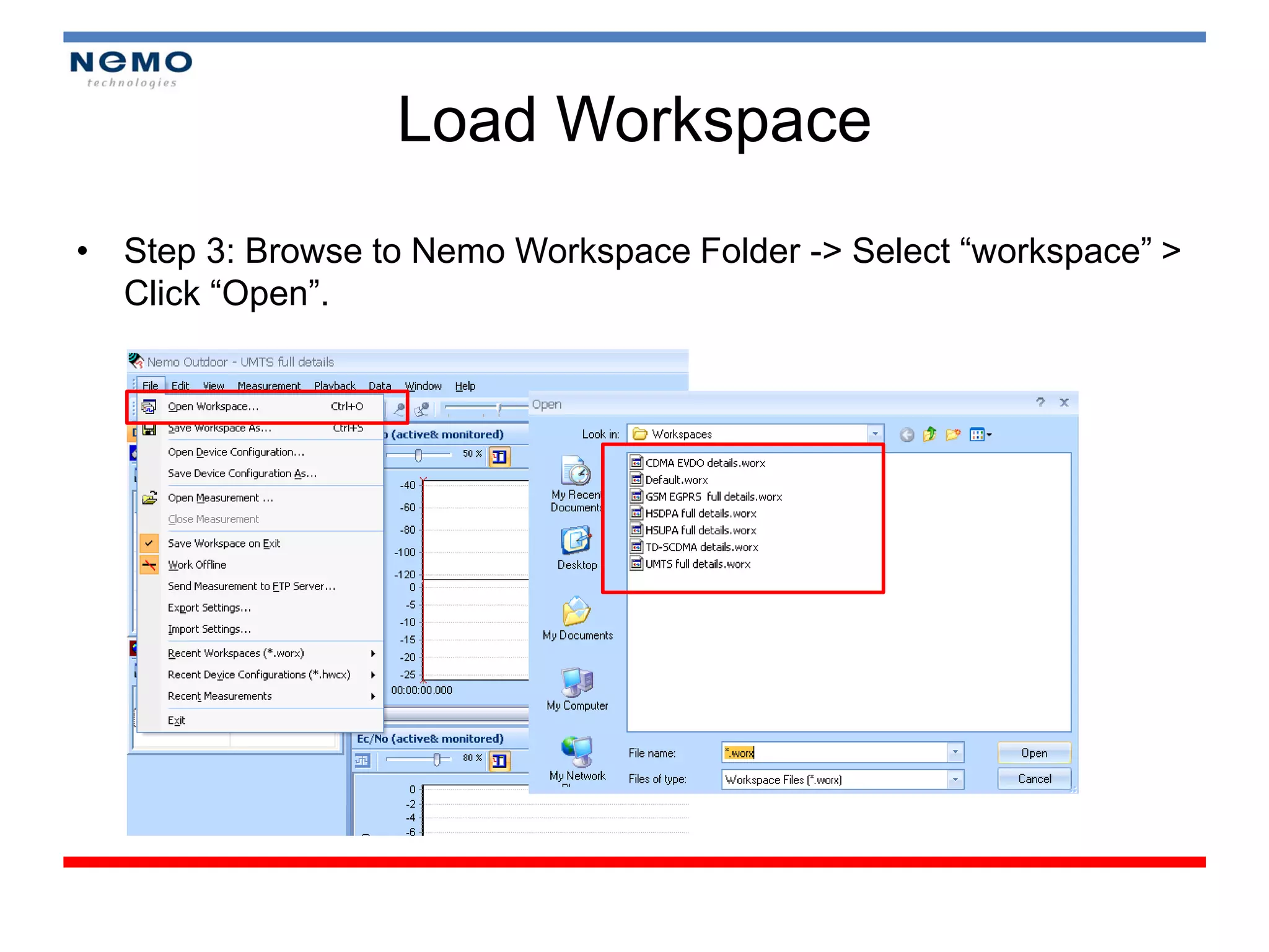
Workspace
• Make sure the Nemo dongle is connected to the laptop.
• Launch Nemo Outdoor 5.07.
• Load the desired workspace.
• Workspace should contains adequate information for the
user to monitor.
• Different workspace should be created for different setup
configuration.
• Nemo workspace are stored proper folder for easy
access, eg.
C:Nemo ToolsNemo OutdoorWorkspaces
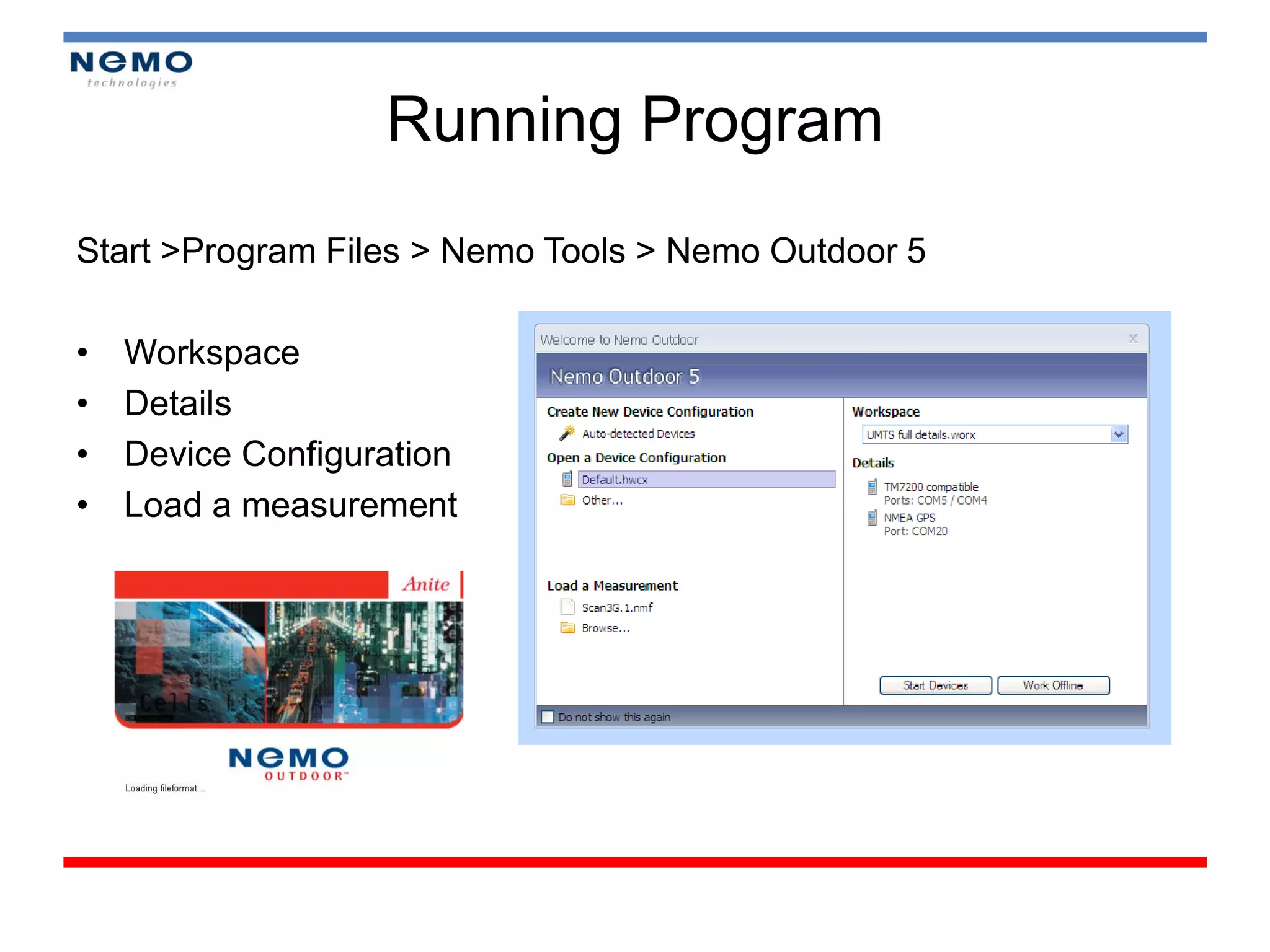
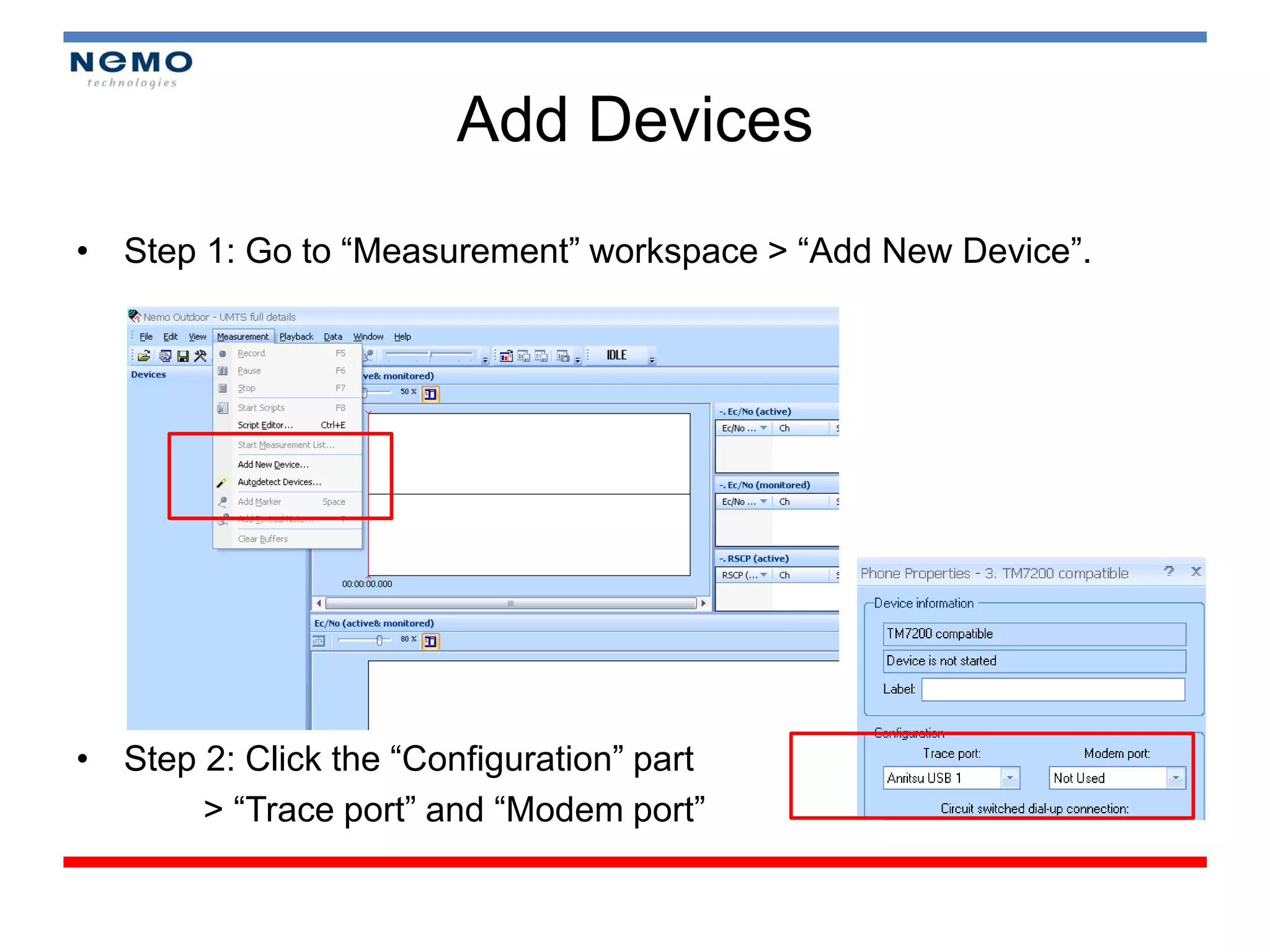
Add Devices
• Step1: Go to “Measurement” workspace > “Add New Device”.
• Step 2: Click the “Configuration” part
> “Trace port” and “Modem port”
44.
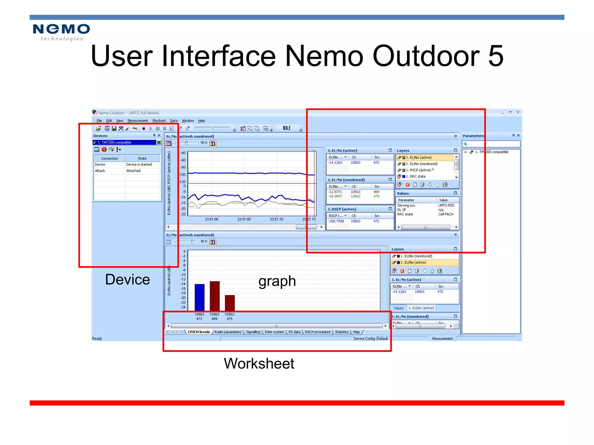
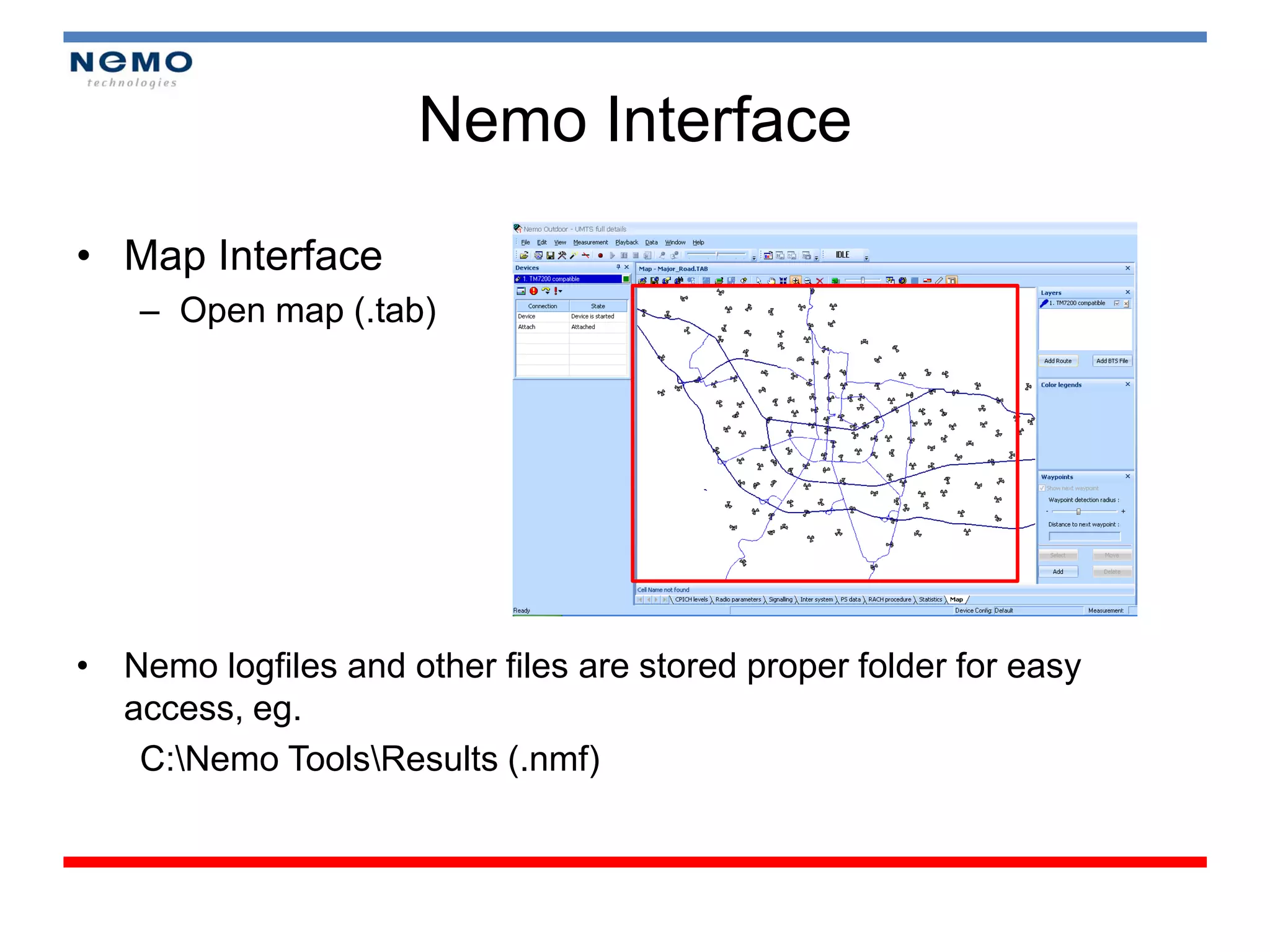
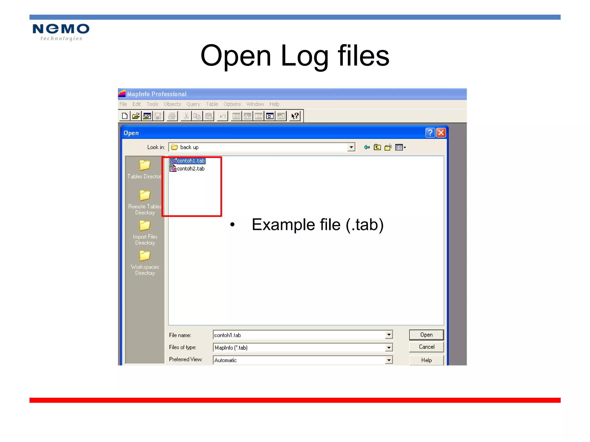
Nemo Interface
• MapInterface
– Open map (.tab)
• Nemo logfiles and other files are stored proper folder for easy
access, eg.
C:Nemo ToolsResults (.nmf)
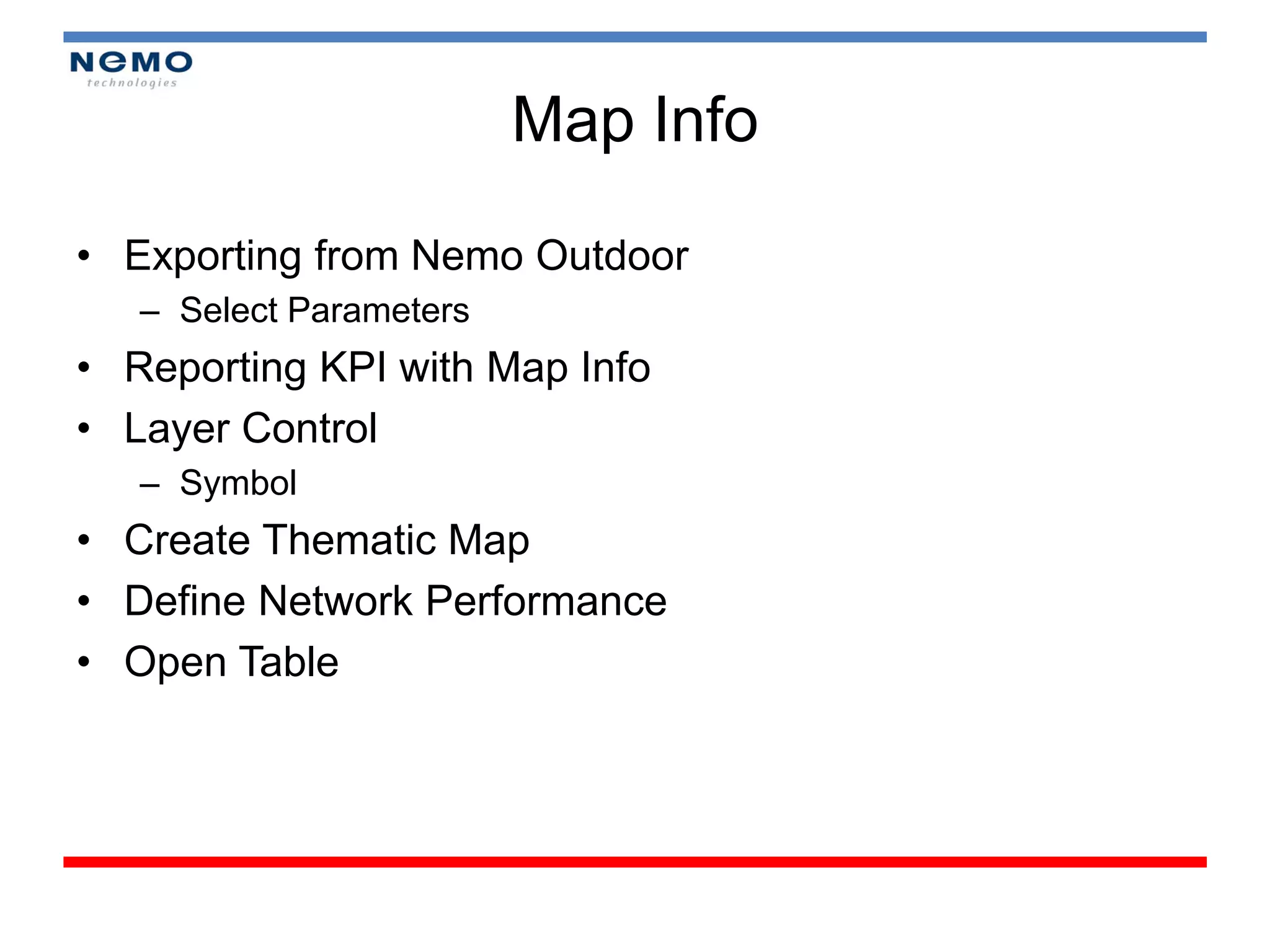
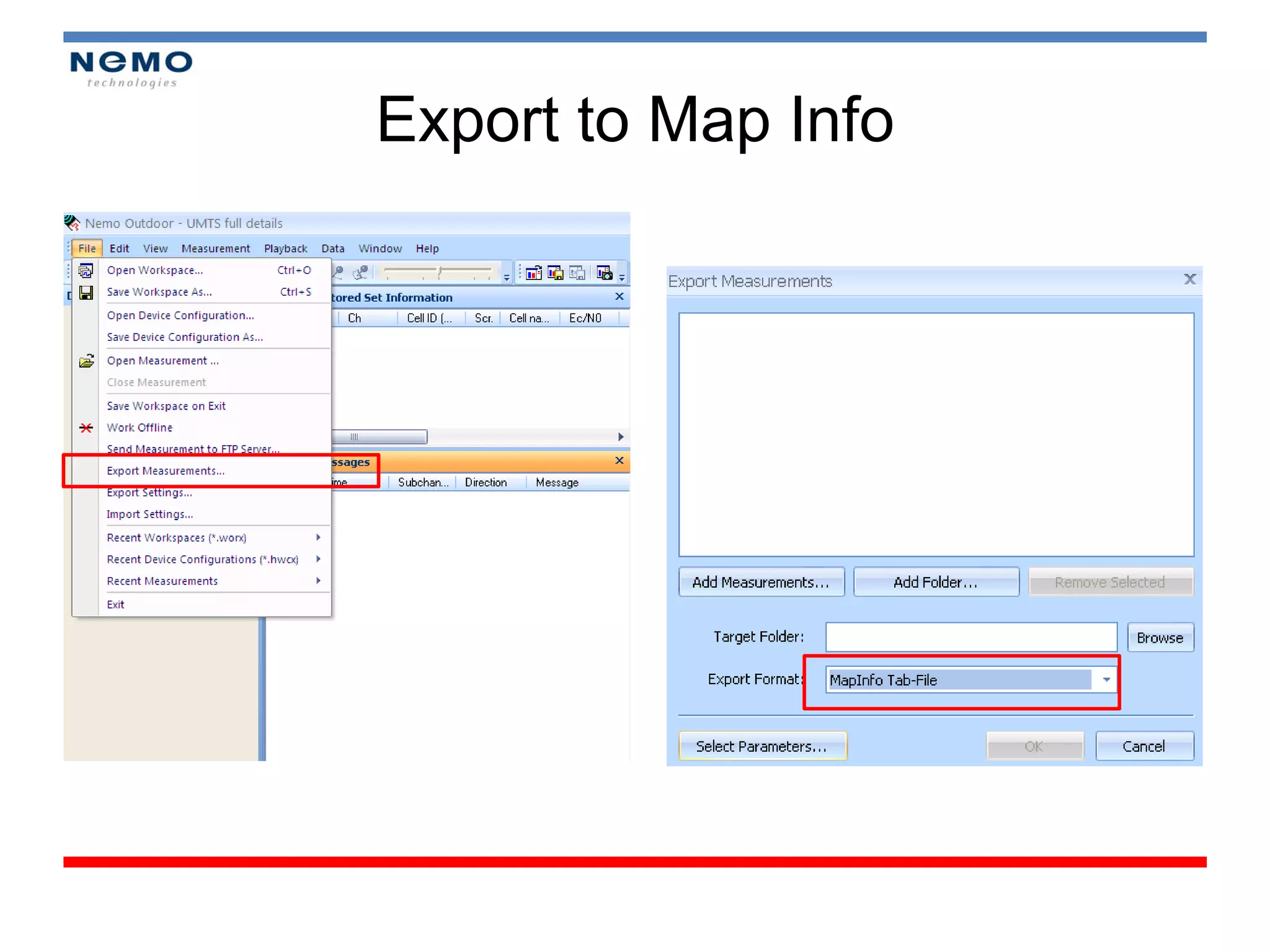
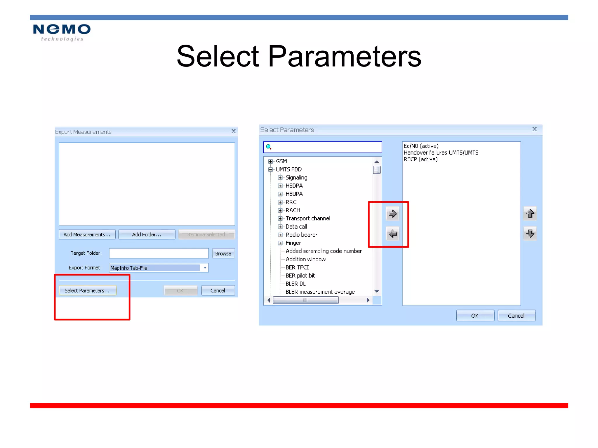
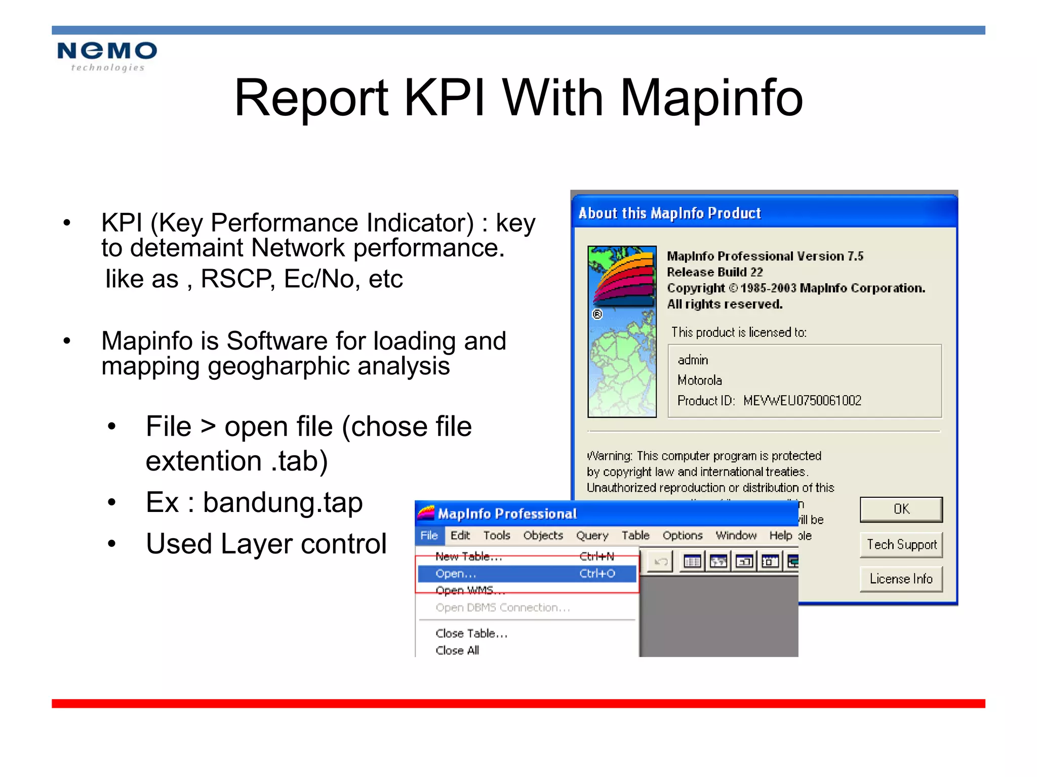
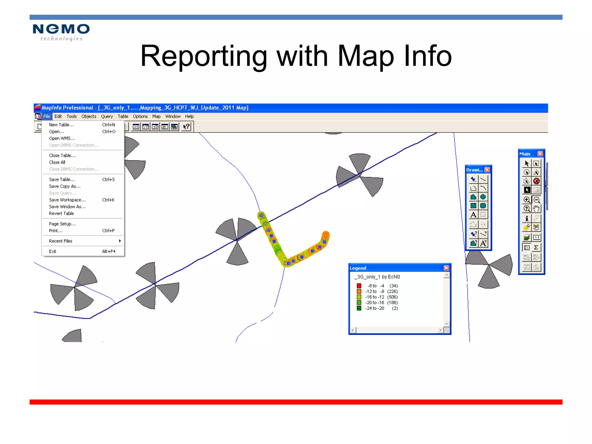
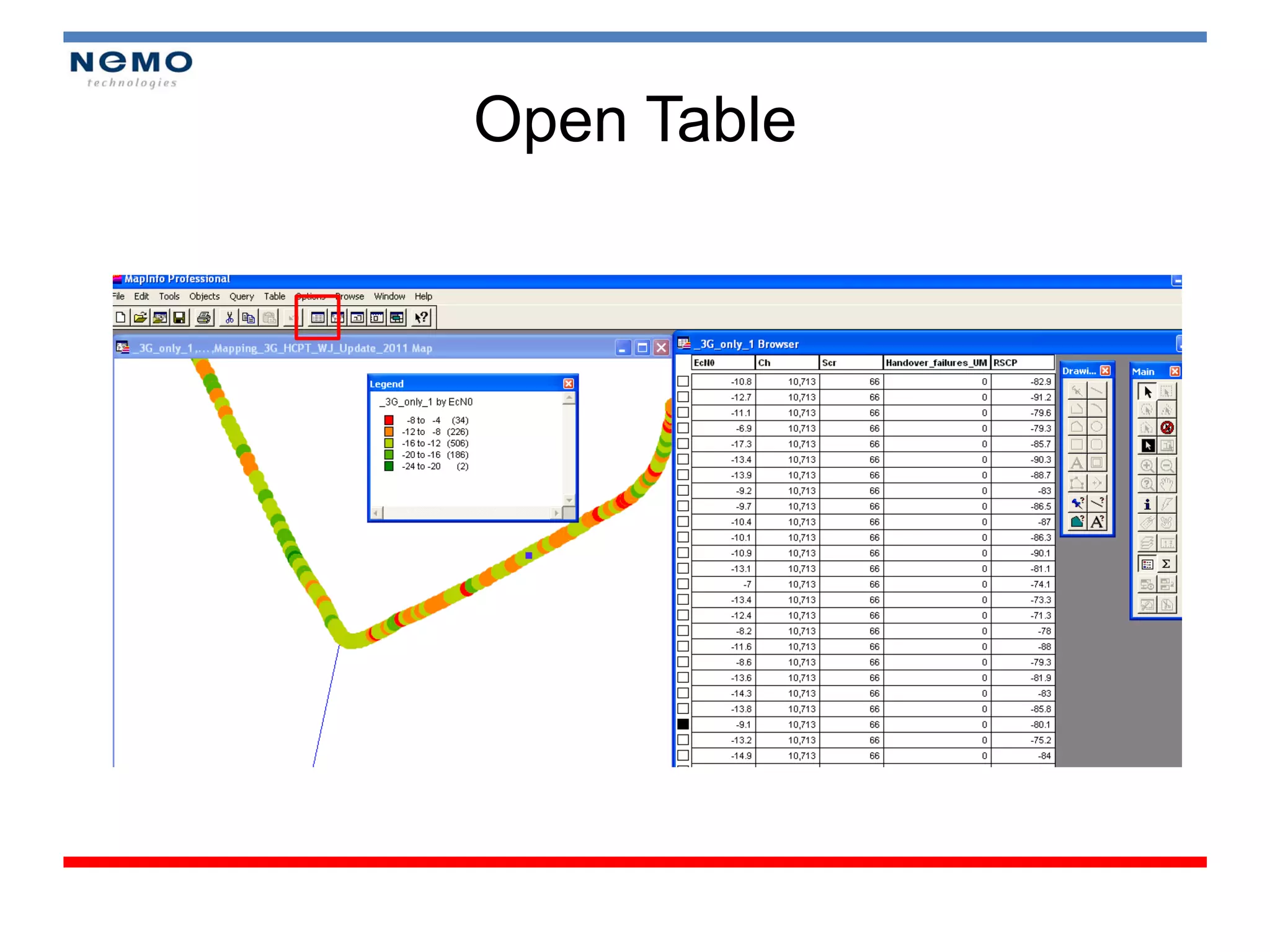
Report KPI WithMapinfo
• KPI (Key Performance Indicator) : key
to detemaint Network performance.
like as , RSCP, Ec/No, etc
• Mapinfo is Software for loading and
mapping geogharphic analysis
• File > open file (chose file
extention .tab)
• Ex : bandung.tap
• Used Layer control
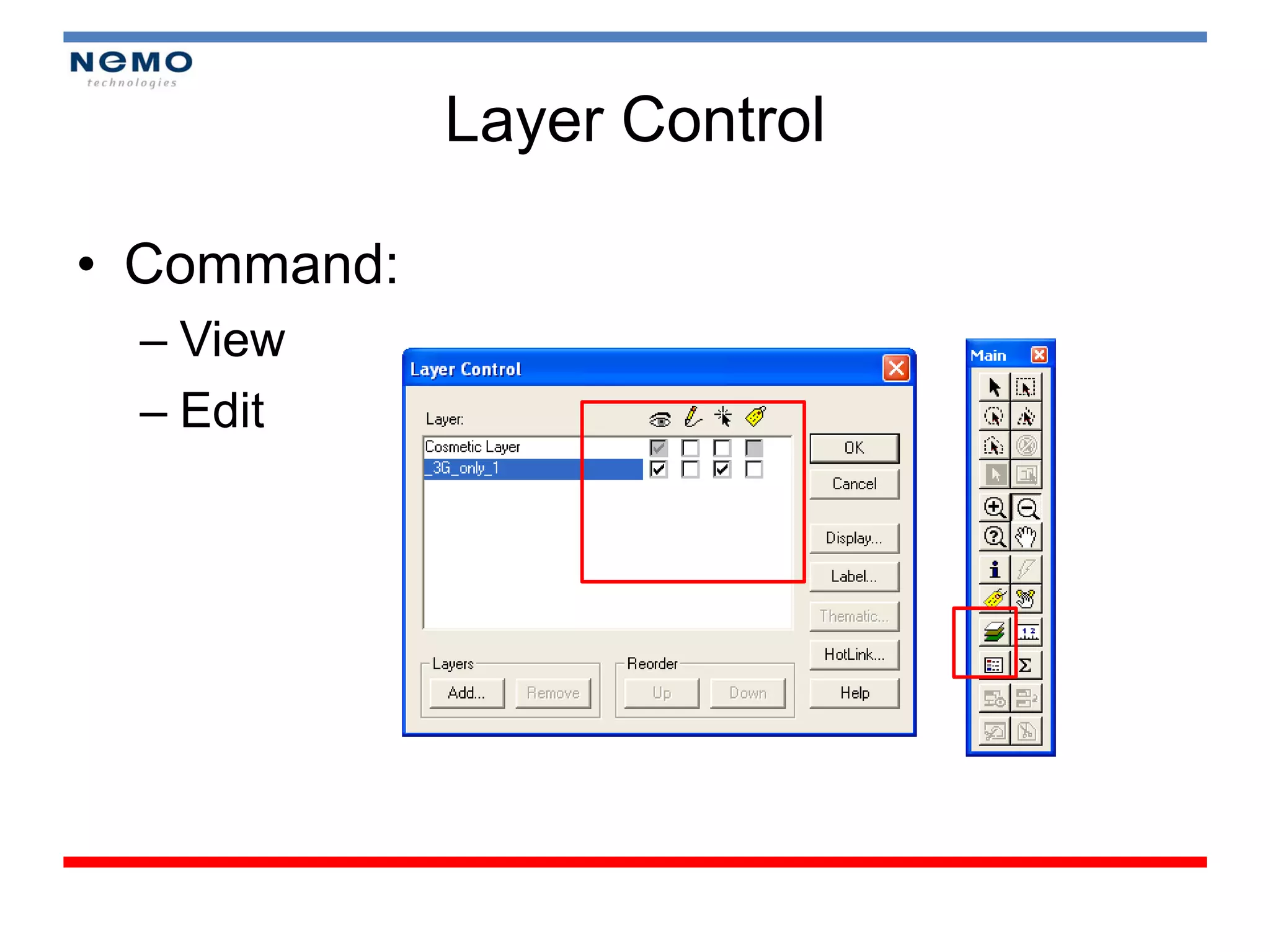
UMTS Optimization
• 3 Mayor Steps in Optimizing Network
• UMTS performance indicator
• Problem Signature
• Tuning network
– Specific Neighbor list
– Managing excessive soft handoff
61.
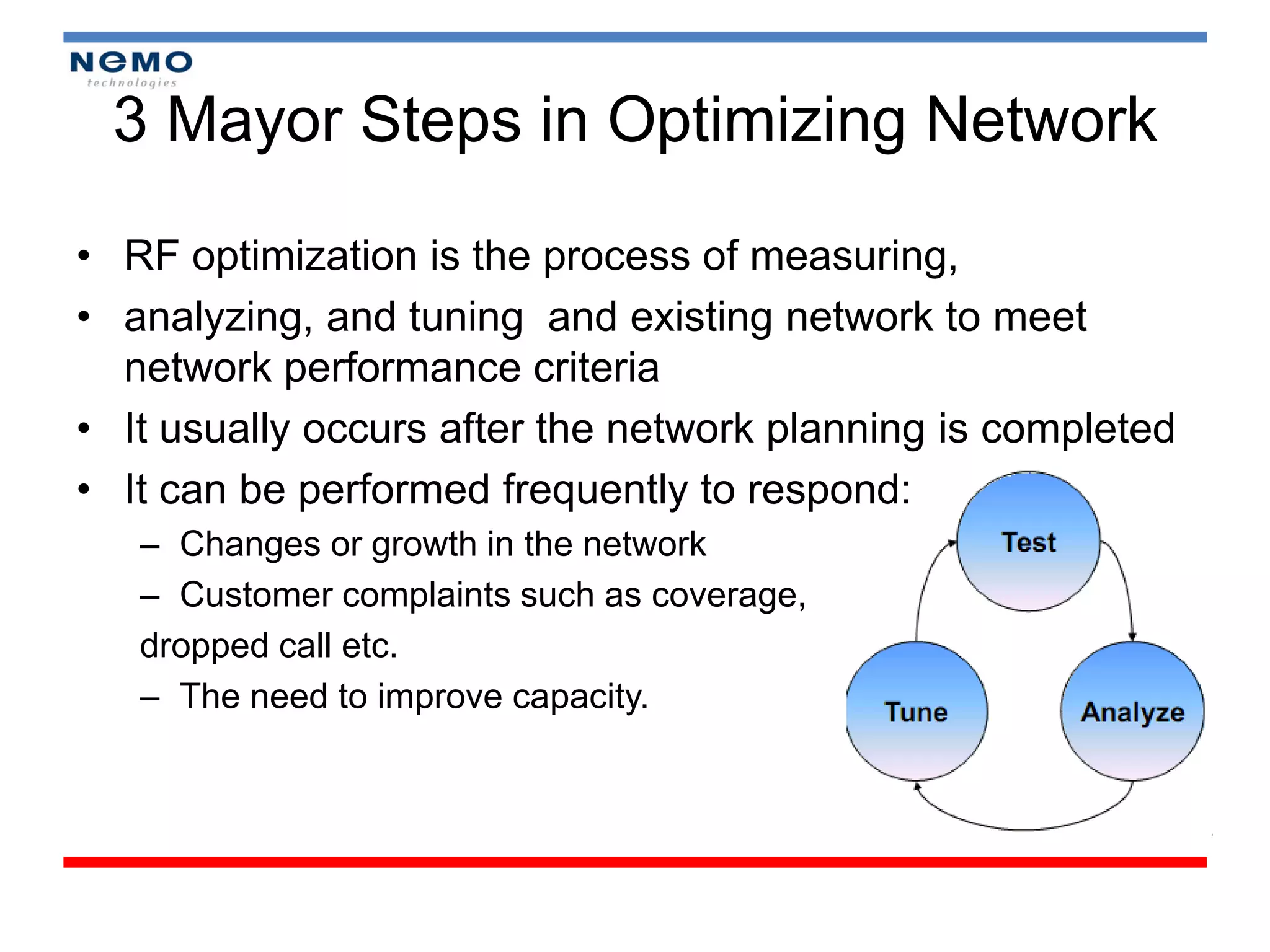
3 Mayor Stepsin Optimizing Network
• RF optimization is the process of measuring,
• analyzing, and tuning and existing network to meet
network performance criteria
• It usually occurs after the network planning is completed
• It can be performed frequently to respond:
– Changes or growth in the network
– Customer complaints such as coverage,
dropped call etc.
– The need to improve capacity.
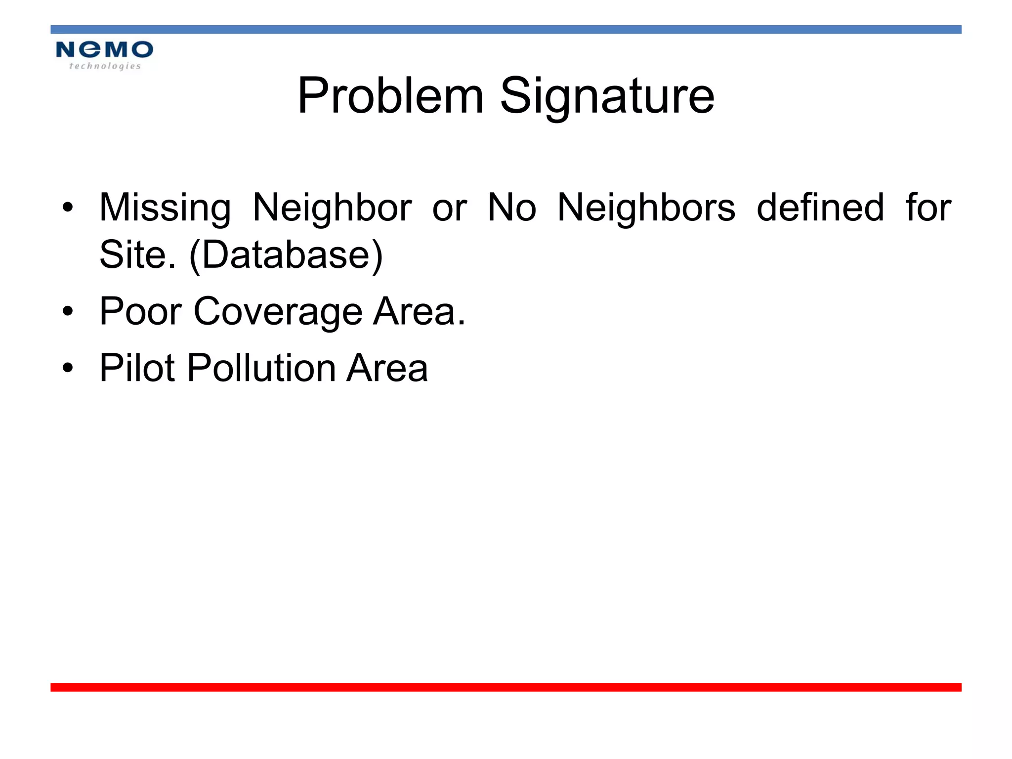
Problem Signature
• MissingNeighbor or No Neighbors defined for
Site. (Database)
• Poor Coverage Area.
• Pilot Pollution Area
64.
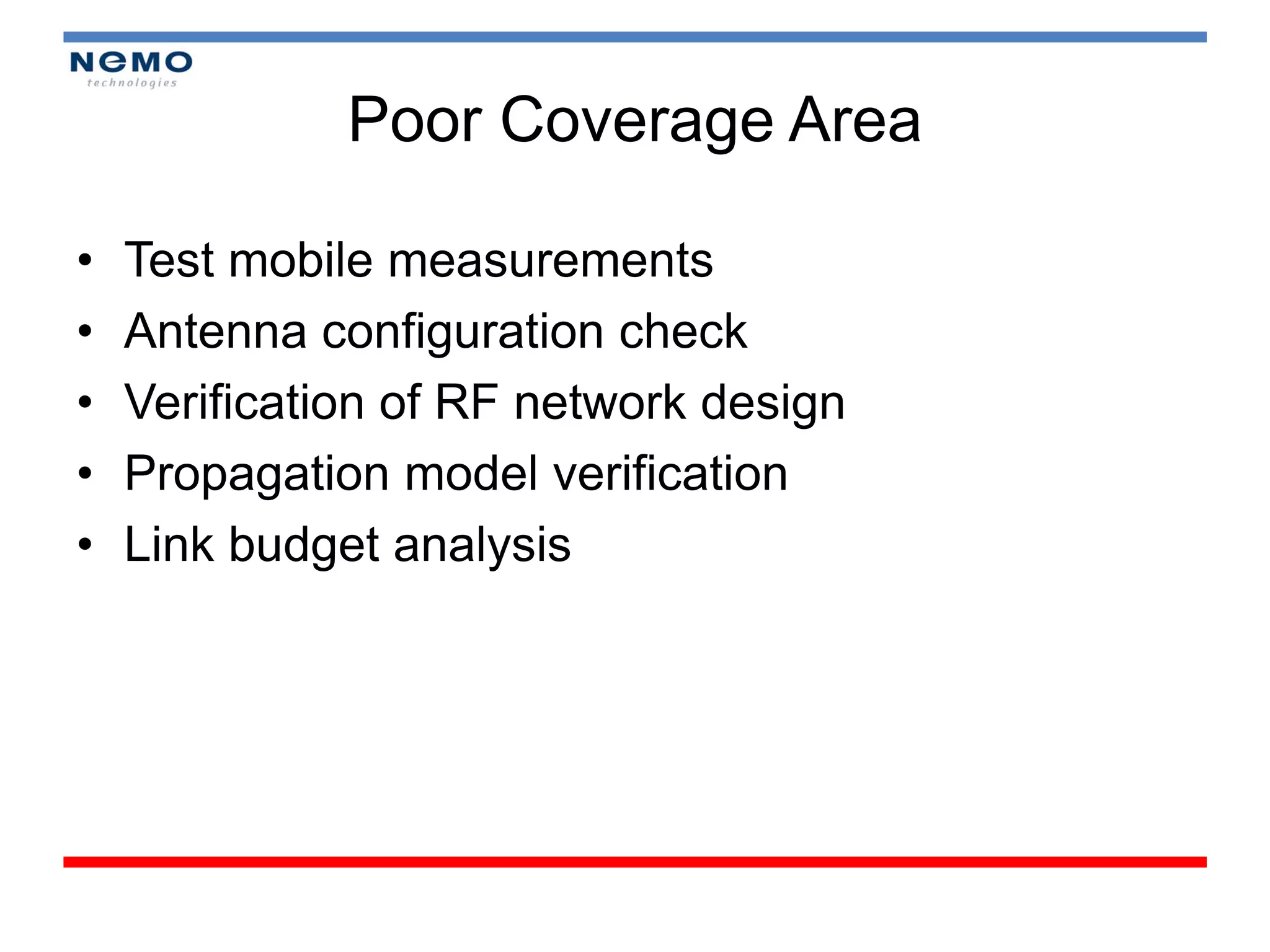
Poor Coverage Area
• Test mobile measurements
• Antenna configuration check
• Verification of RF network design
• Propagation model verification
• Link budget analysis
65.
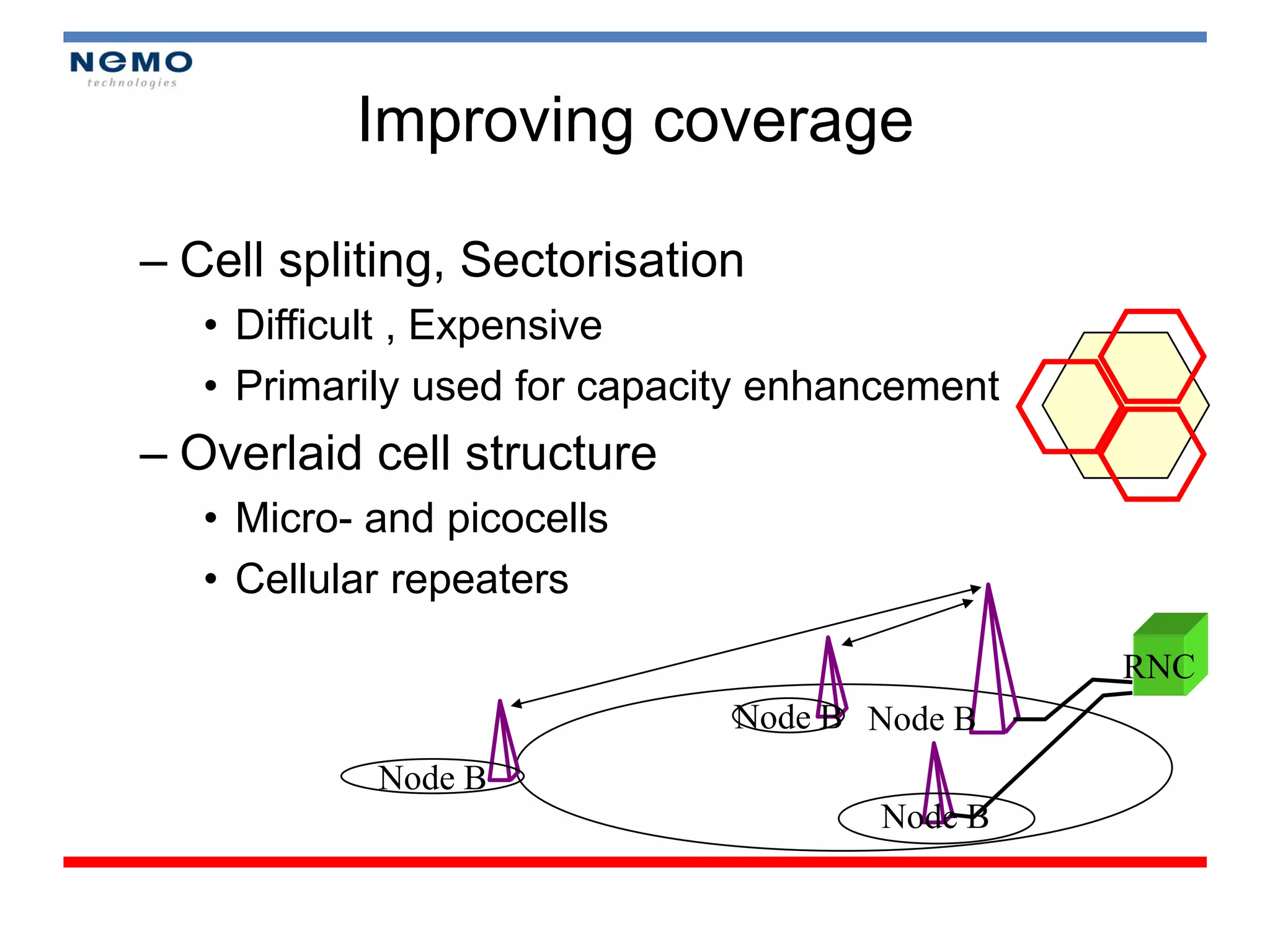
Improving coverage
– Cellspliting, Sectorisation
• Difficult , Expensive
• Primarily used for capacity enhancement
– Overlaid cell structure
• Micro- and picocells
• Cellular repeaters
RNC
Node B Node B
Node B
Node B
66.
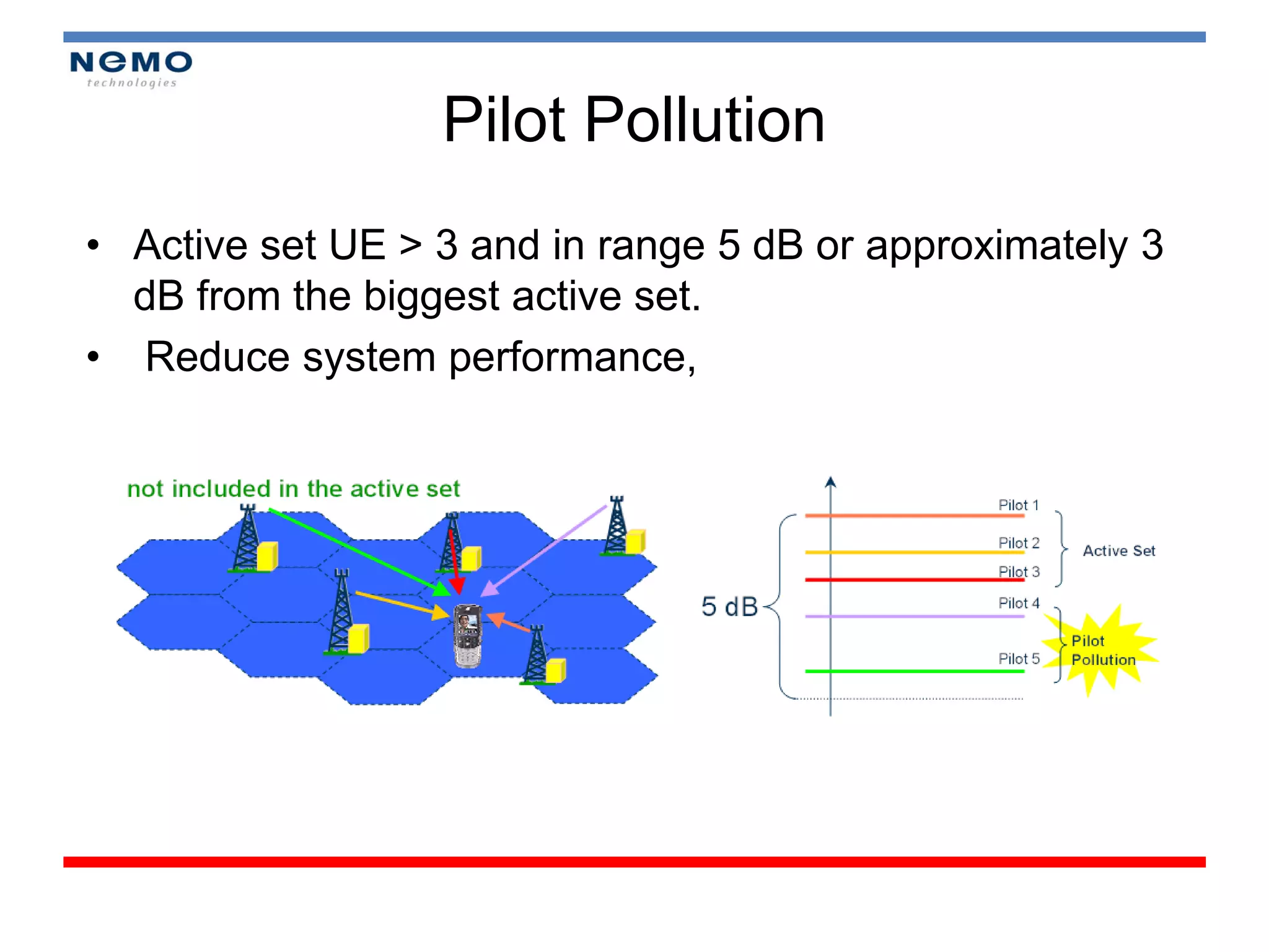
Pilot Pollution
• Activeset UE > 3 and in range 5 dB or approximately 3
dB from the biggest active set.
• Reduce system performance,
67.
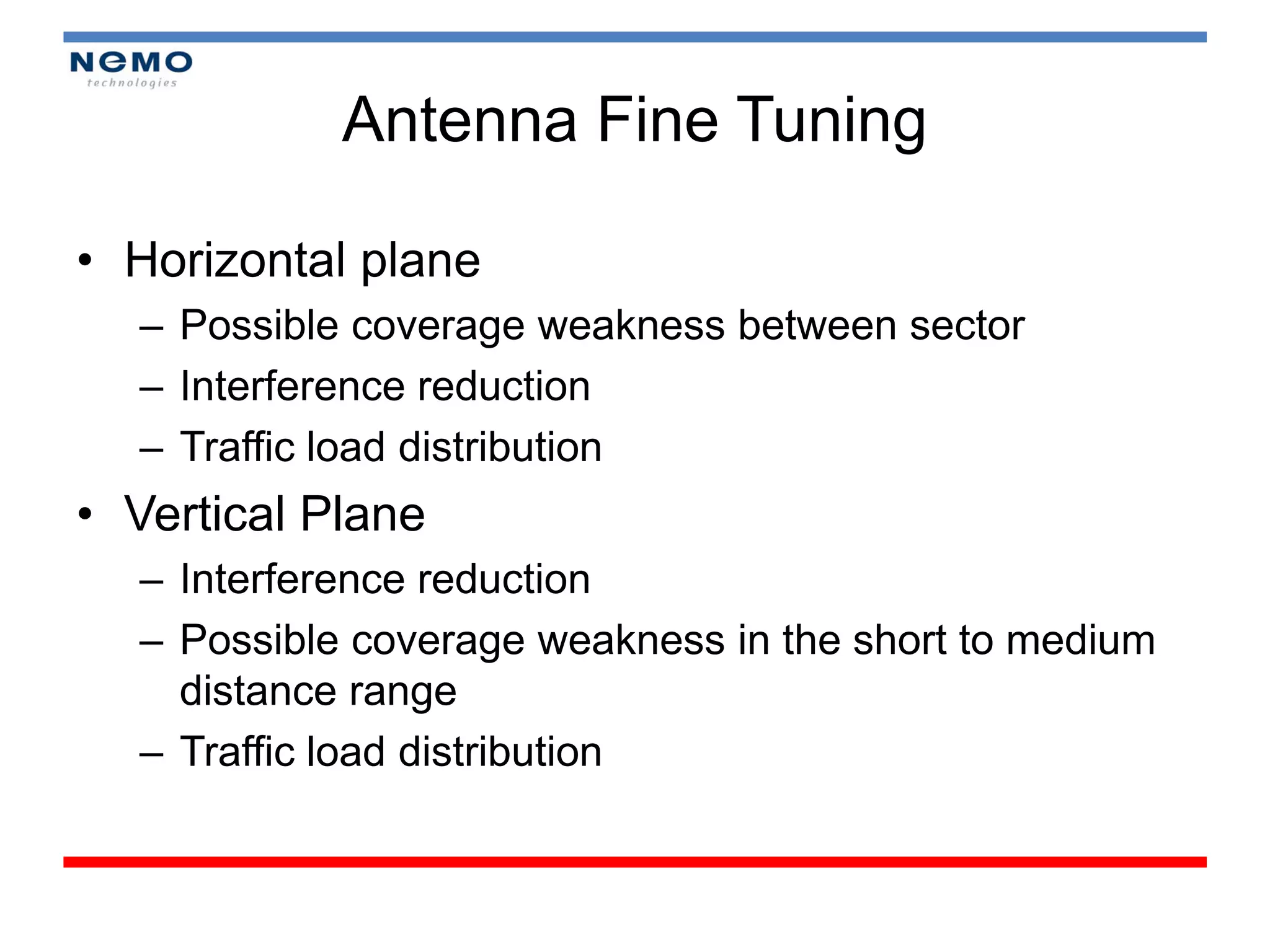
Antenna Fine Tuning
•Horizontal plane
– Possible coverage weakness between sector
– Interference reduction
– Traffic load distribution
• Vertical Plane
– Interference reduction
– Possible coverage weakness in the short to medium
distance range
– Traffic load distribution
68.
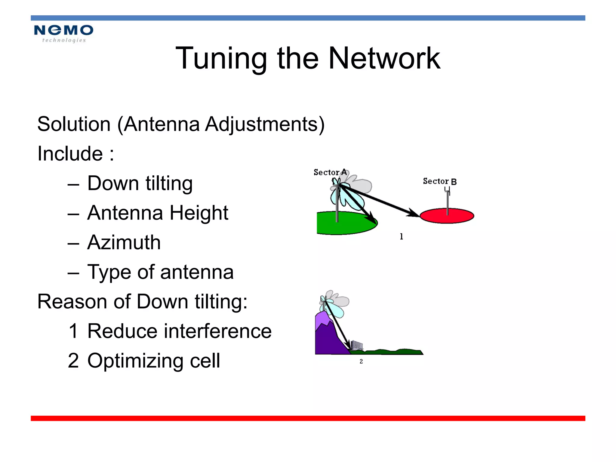
Tuning the Network
Solution(Antenna Adjustments)
Include :
– Down tilting
– Antenna Height
– Azimuth
– Type of antenna
Reason of Down tilting:
1 Reduce interference
2 Optimizing cell
69.
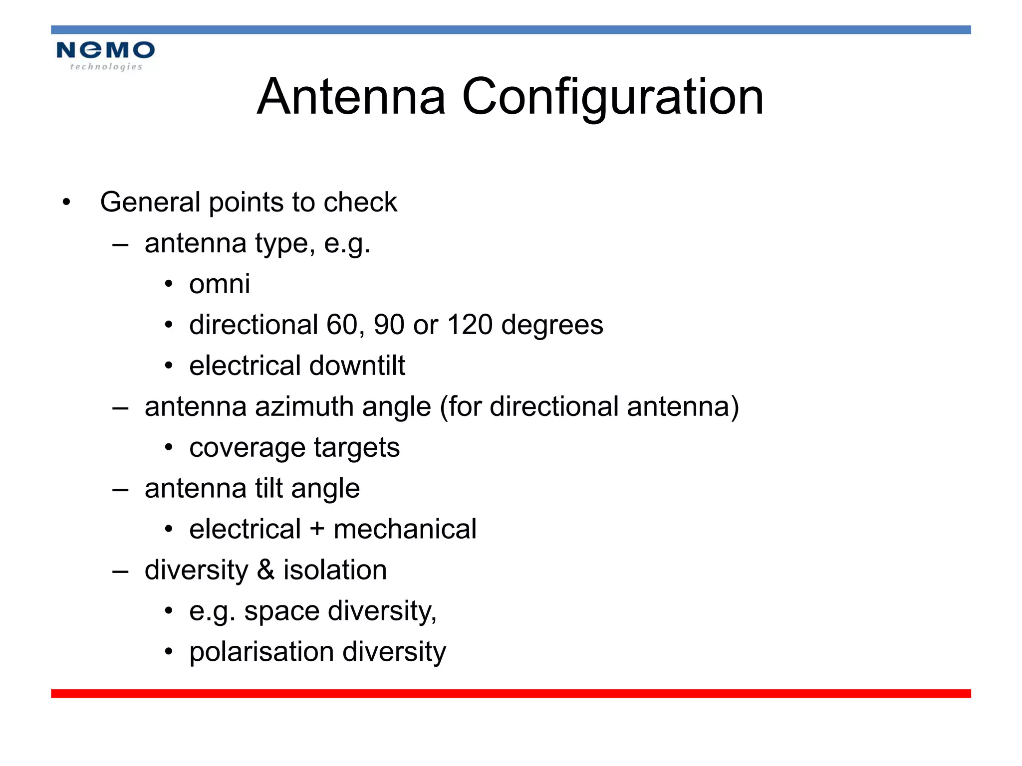
Antenna Configuration
• Generalpoints to check
– antenna type, e.g.
• omni
• directional 60, 90 or 120 degrees
• electrical downtilt
– antenna azimuth angle (for directional antenna)
• coverage targets
– antenna tilt angle
• electrical + mechanical
– diversity & isolation
• e.g. space diversity,
• polarisation diversity
70.
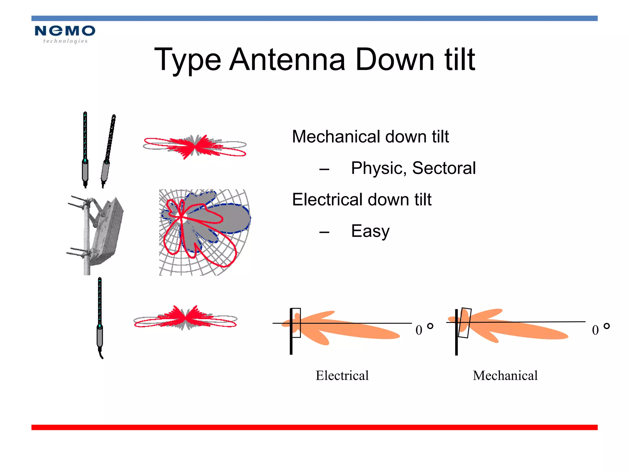
Type Antenna Downtilt
Mechanical down tilt
– Physic, Sectoral
Electrical down tilt
– Easy
0° 0°
Electrical Mechanical
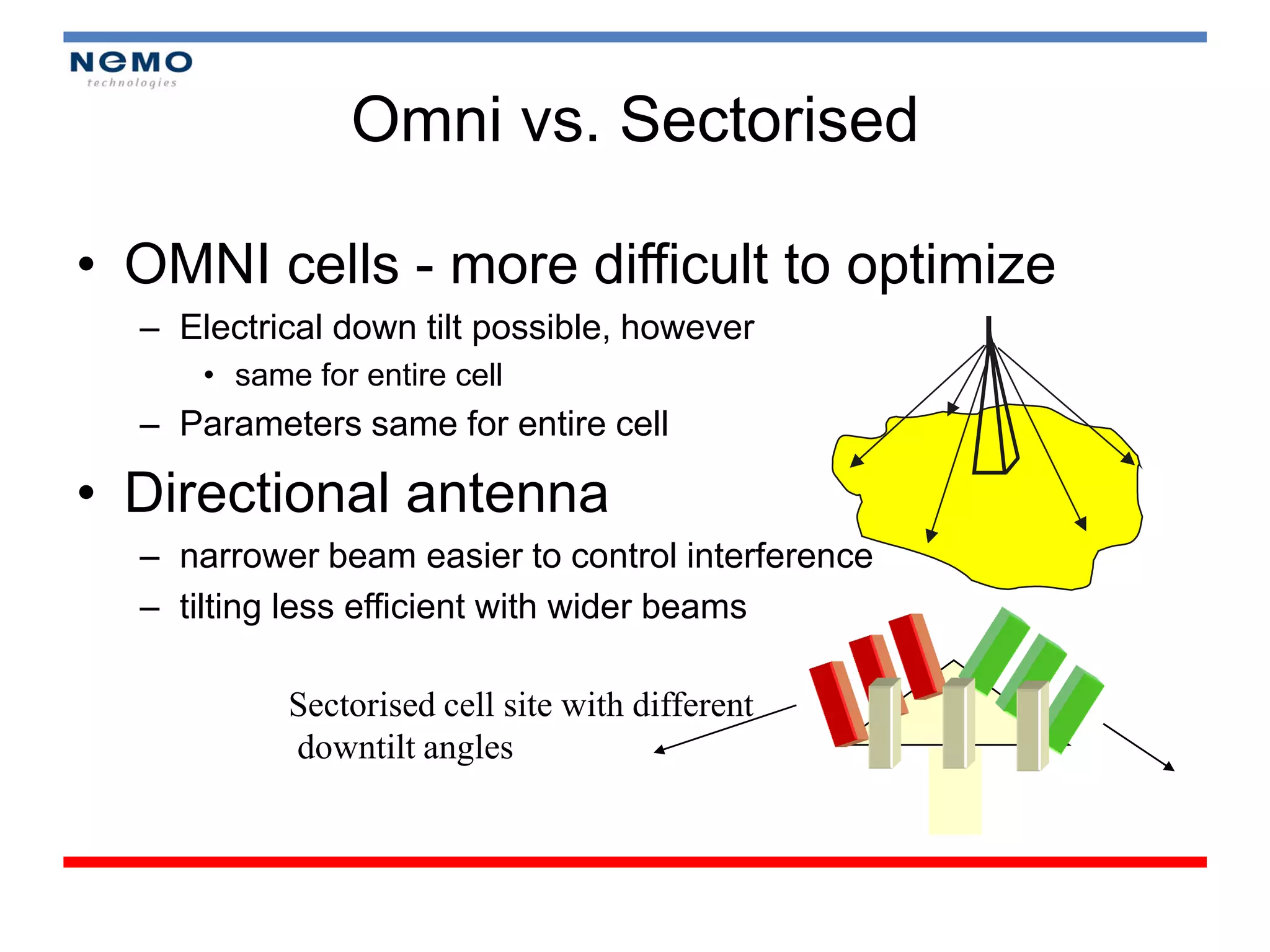
Omni vs. Sectorised
•OMNI cells - more difficult to optimize
– Electrical down tilt possible, however
• same for entire cell
– Parameters same for entire cell
• Directional antenna
– narrower beam easier to control interference
– tilting less efficient with wider beams
Sectorised cell site with different
downtilt angles
73.
Reference
• Short Course“In Building DCS 1800 Coverage”, Mobile
Communication Laboratory, 2009
• Short Course “Drive Test UMTS”, Mobile Communication
Laboratory, 2008
• Short Course “Drive Test CDMA 2001x and Optimization”, Mobile
Communication Laboratory, 2008
• Short Course “CDMA Drive Test and Optimization”, Antenna
Laboratory, 2007
• Nemo_Outdoor_manual


![Nemo outdoor 6_training_aug2011 [compatibility mode]](https://cdn.slidesharecdn.com/ss_thumbnails/nemooutdoor6trainingaug2011compatibilitymode-130826015745-phpapp02-thumbnail.jpg?width=640&height=640&fit=bounds)


