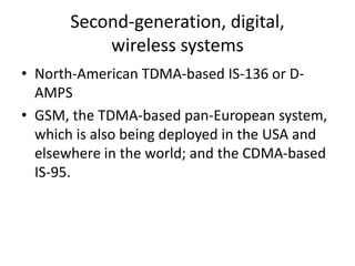
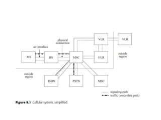
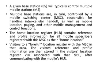
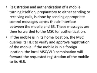
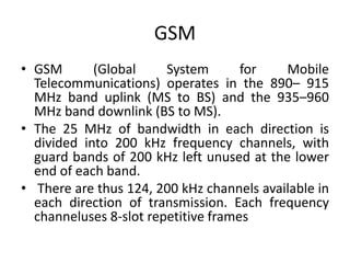
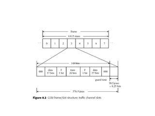
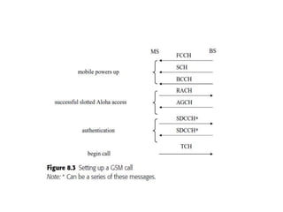
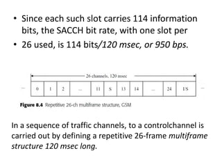
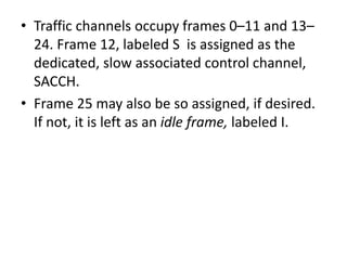
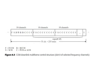
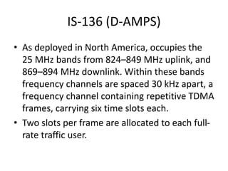
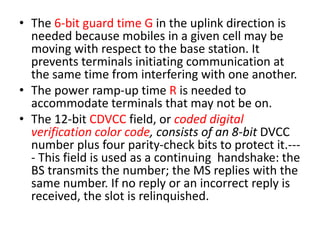
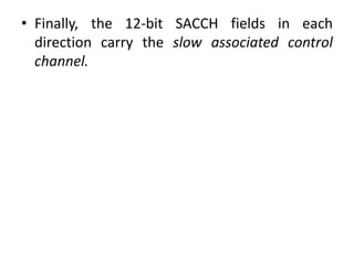
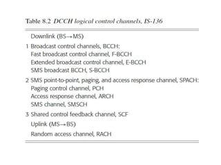
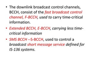
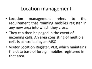
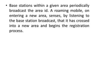
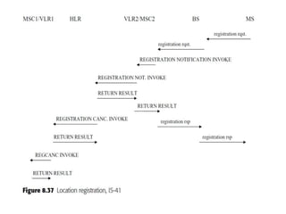
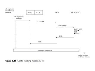
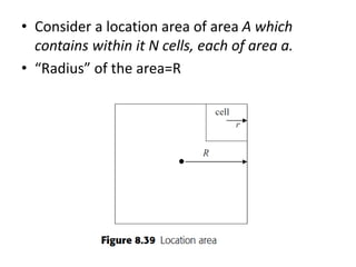
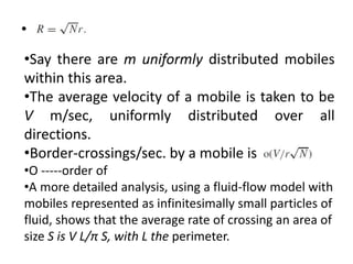
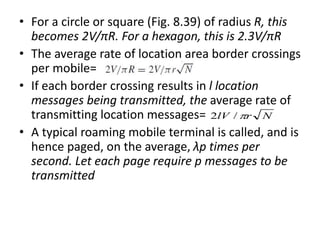
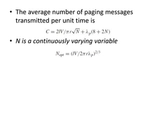
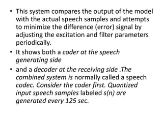
Structural Analysis and Design of Foundations: A Comprehensive Handbook for S...
Module 4 Mobile comm GSM 3 G 4 G
1. Second-generation, digital,
wireless systems
• North-American TDMA-based IS-136 or D-
AMPS
• GSM, the TDMA-based pan-European system,
which is also being deployed in the USA and
elsewhere in the world; and the CDMA-based
IS-95.
2.
3. • A given base station (BS) will typically control multiple
mobile stations (MS)
• Multiple base stations are, in turn, controlled by a
mobile switching center (MSC), responsible for
handling inter-cellular handoff, as well as mobile
location, paging, and other mobile management and
control functions.
• The home location register (HLR) contains reference
and profile information for all mobile subscribers
registered with this MSC as their “home location.”
• Visitors to a “foreign” location register with the MSC in
that area. The visitors’ reference and profile
information are then stored in the visitors’ location
register VLR associated with that MSC, after
communicating with the mobile’s HLR.
4. • Registration and authentication of a mobile
turning itself on, preparatory to either sending or
receiving calls, is done by sending appropriate
control messages across the air interface
between the mobile and BS. These messages are
then forwarded to the MSC for authentication.
• If the mobile is in its home location, the MSC
queries its HLR to verify and approve registration
of the mobile. If the mobile is in a foreign
location, the local MSC/VLR combination will
forward the requested registration of the mobile
to its HLR.
5. GSM
• GSM (Global System for Mobile
Telecommunications) operates in the 890– 915
MHz band uplink (MS to BS) and the 935–960
MHz band downlink (BS to MS).
• The 25 MHz of bandwidth in each direction is
divided into 200 kHz frequency channels, with
guard bands of 200 kHz left unused at the lower
end of each band.
• There are thus 124, 200 kHz channels available in
each direction of transmission. Each frequency
channeluses 8-slot repetitive frames
6.
7. • A 26-bit training sequence in the middle of the
slot is used to provide an estimate of the radio
channel, to be used in training an adaptive
equalizer at the receiver to help overcome the
multipath fading that may be encountered.
• The two one-bit flag (F) bits indicate whether
the data fields carry user or control traffic.
8.
9. • On powering on in any cell, the mobile must first
lock onto or acquire the frequencies used in that
cell, and then synchronize to the framing-time
slot structure
• it first searches for a specific control channel, the
frequency correction channel, FCCH, broadcast by
the local BS, which enables it to adjust or
synchronize its frequency characteristic to that of
the base station
• The FCCH message is always followed by the
synchronization channel, SCH, message, which
identifies the BS and provides frame, hence time,
synchronization to the mobile.
10. • Once frequency and timing information is
acquired, the mobile listens to a channel
called the broadcast control channel, BCCH,
which provides information needed to set up
the call: the cell configuration, the network to
which it belongs, access information, and
control channel information, among other
items.
11. • The mobile terminal is ready to initiate a call. It
does this by sending a random access request
message over the random access channel, RACH,
which carries a 5-bit random number plus a 3-bit
purpose indicator.
• If the access attempt is successful, the BS
acknowledges receipt of the RACH message with
an access grant channel, AGCH, message.
• This message repeats the 8-bit request message,
and directs the terminal to a specified stand-
alone channel, SDCCH, over which the mobile
transmits the signaling information required for
authentication, as well as to make the desired
call connections.
12. • If the call setup is approved, the BS replies to
the MS with SDCCH messages directing the
mobile to the frequency/time slot traffic
channel (TCH) to use for actually beginning
the call and sending the desired user
information.
• The control channels are grouped into three
categories: broadcast channels, common
control channels, and dedicated control
channels.
13.
14. • The paging channel, as the name indicates, is
used by a base station to locate a mobile for
an incoming call.
• The random access channel, is directed uplink,
from MS to BS.
• The dedicated control channels are bi-
directional, allowing mobile signaling,
management, and supervisory information to
be transmitted in either direction.
15. • and broadcast channel measurement results
from neighboring cells to be used for
mobileassisted
• handoffs. The fast associated control channel,
FACCH, is used to send handoff
• requests and other urgent signaling messages.
It is sent on a normal traffic channel, TCH,
• or an SDCCH, interrupting that channel for this
purpose.
16. • In particular, the slow associated control
channel, SACCH, is used by the BS, in the
downlink direction, to send transmitter power
level and timing advance instructions to the
MS.
• The mobile uses this channel, in the reverse,
uplink direction, to send the base station
indications of received signal strength.
• The fast associated control channel, FACCH, is
used to send handoff requests and other
urgent signaling messages
17. • The stand-alone dedicated control channel,
SDCCH, used in both directions on a temporary
basis before assigning dedicated TCHs to a
mobile-base station duplex (two-way)
connection.
• GSM uses three different ways of allocating time
slots to the other control channels: It sets aside a
prescribed number of frequency channels of the
124 available in each direction and “robs” one
time slot per frame
• It uses a regular traffic channel time slot, when
needed, by setting the TCH flag bit.
18. • The allocation of one time slot in 13, in a
sequence of traffic channels, to a control
channel is carried out by defining a repetitive
26-frame multiframe structure 120 msec long.
• Traffic channels occupy frames 0–11 and 13–
24. Frame 12, labeled S is assigned as the
dedicated, slow associated control channel,
SACCH.
• Frame 25 may also be so assigned, if desired.
If not, it is left as an idle frame, labeled I.
19. • Since each such slot carries 114 information
bits, the SACCH bit rate, with one slot per
• 26 used, is 114 bits/120 msec, or 950 bps.
In a sequence of traffic channels, to a controlchannel is
carried out by defining a repetitive 26-frame multiframe
structure 120 msec long.
20. • Traffic channels occupy frames 0–11 and 13–
24. Frame 12, labeled S is assigned as the
dedicated, slow associated control channel,
SACCH.
• Frame 25 may also be so assigned, if desired.
If not, it is left as an idle frame, labeled I.
21.
22. • This 51-frame multi frame structure is
diagrammed.
• The 51 frames, repeating every 235 msec, are
organized into five 10-frame groups, the first
channel in each group, labelled F
corresponding to the frequency correction
channel, FCCH.
• Each FCCH is immediately followed by the
synchronization channel, SCH, used by a
mobile to establish frame, hence time,
synchronization. This channel is labelled S.
23. • The broadcast control channel, BCCH, labelled
B in Fig. 8.5, used to provide information
needed to set up a call.
• The remaining channels indicated by the letter
C, correspond to either access channels (ACH)
or paging channels (PCH).
24.
25. • Fig. 8.6(a). Figure 8.6(b) show the 78-bit data
field is actually generated from a 25-bit
information message.
• This message is protected against errors, first,
by a 10-bit cyclic redundancy code (CRC)
which adds ten parity bits, and then by a rate-
1/2 convolutional code.
26.
27. • Figure 8.7 portrays the generation of the 456
bits.
• These 456 bits are themselves generated from
a 184-bit information message that is
protected by an error-correcting code with 40
parity bits followed by rate-1/2 convolutional
coding
29. • A paging channel, as the name indicates, is used
to locate a mobile in a particular cell for an
incoming call.
• The traffic channel slots were shown there to
contain 148 bits, followed by a 30.5 sec guard
time.
• Figure shows how the 78-bit data field is actually
generated from a 25-bit information message.
• This message is protected against errors, first, by
a 10-bit cyclic redundancy code (CRC) which adds
ten parity bits, and then by a rate-1/2
convolutional code
30. • CRC provides the outer coding
• The convolutional coder carries out the inner
coding.
31. IS-136 (D-AMPS)
• As deployed in North America, occupies the
25 MHz bands from 824–849 MHz uplink, and
869–894 MHz downlink. Within these bands
frequency channels are spaced 30 kHz apart, a
frequency channel containing repetitive TDMA
frames, carrying six time slots each.
• Two slots per frame are allocated to each full-
rate traffic user.
32. • The system transmission rate is 48.6 kbps:
1944 bits/frame (324 bits per slot) are
transmitted in 40 msec.
33.
34. • Occupies the 25 MHz bands from 824–849
MHz uplink, and 869–894 MHz downlink.
Within these bands frequency channels are
spaced 30 kHz apart, a frequency channel
containing repetitive TDMA frames, carrying
six time slots each.
• The system transmission rate is 48.6 kbps:
1944 bits/frame (324 bits per slot) are
transmitted in 40 msec.
35. • The 6-bit guard time G in the uplink direction is
needed because mobiles in a given cell may be
moving with respect to the base station. It
prevents terminals initiating communication at
the same time from interfering with one another.
• The power ramp-up time R is needed to
accommodate terminals that may not be on.
• The 12-bit CDVCC field, or coded digital
verification color code, consists of an 8-bit DVCC
number plus four parity-check bits to protect it.---
- This field is used as a continuing handshake: the
BS transmits the number; the MS replies with the
same number. If no reply or an incorrect reply is
received, the slot is relinquished.
36. • Finally, the 12-bit SACCH fields in each
direction carry the slow associated control
channel.
37.
38. • The downlink broadcast control channels,
BCCH, consist of the fast broadcast control
channel, F-BCCH, used to carry time-critical
information.
• Extended BCCH, E-BCCH, carrying less time-
critical information
• SMS BCCH --S-BCCH, used to control a
broadcast short message service defined for
IS-136 systems.
39. • The SMS point-to-point, paging, and access
response channel, SPACH, is a logical channel
designed, to carry paging and access response
control information, as well as point-to-point
messages concerning the SMS service.
• Shared control feedback, SCF, channel is used
to carry downlink information, from BS to MS.
•
40. Repetitive super frame structure, IS-
136
• The broadcast channels are transmitted sequentially
using a repetitive super frame structure.
• Each super frame corresponds to 16 consecutive
TDMA frames, for a total time interval of 640 msec
41.
42. • The slot format of control channels appears in
Fig. 8.11.
• Each slot carries 28-bit synchronization field
and a total of 260 bits of data.
• The SCF channel is used to respond to the
mobile’s random access attempt.
• CSFP field is used to indicate the location of
a TDMA block within a super frame.
43. • Random access messages, used for call setup
or origination, as well as mobile registration
and authentication, are carried over the one
uplink channel, the random access channel,
RACH.
• 12-bit CSFP field (for coded super frame
phase) is used to indicate the location of a
TDMA block within a super frame.
• This field carries an 8-bit SFP (superframe
phase) number and four parity-check bits to
protect this number against errors.
44.
45. • This is the layer-3 data field carrying one of
the various F-BCCH messages.
• The 8-bit parameter L3LI is the length
indicator
• Figure 8.14(a) represents the frame format
used when an F-BCCH message can be
transmitted completely within one frame. If a
message requires more than one frame for
completion, the Begin and Continue formats
of Figs. 8.14(b) and (c) are used.
46. • The one-bit EI flag set to 1 indicates that filler
(all 0s) has been used to pad out the frame; EI
= 0 says that a new message follows.
• EC is used to designate a change in the E-
BCCH.
• The 7-bit CLI, or Continuation Length
Indicator, in the Continue frame of Fig. 8.14(c),
is used to indicate the number of bits
belonging to a Continue message.
47.
48. • The IS-136 access procedure is diagrammed in Fig. 8.15
• The mobile station listens to a downlink SCF channel to
determine a specific future time slot to use to send its
RACH message
• It then sends the RACH message
• A later SCF message, carried in a specified time slot,
will indicate whether the RACH message has been
correctly received and access granted.
• If access is granted, an ARCH message carried on the
SPACH channel will follow, indicating the specific digital
traffic channel the mobile is to use for communication.
If the access is not successful (other mobiles might be
attempting access at the same time) the access
attempt will be retried a random time later.
49. IS-95
• IS-95 is a CDMA-based system. Its traffic and
control channels are defined as specified
codes rather than time slots as in the case of
GSM and IS-136.
50.
51.
52. • A binary information stream is “multiplied” by
a pseudo-noise (PN) chip spreading sequence,
the resulting output shaped by an appropriate
low-pass shaping filter, and then fed to a high-
frequency transmitter.
• For full-rate traffic transmission of 8.6 kbps
• IS-95 defines consecutive 172-bit traffic
frames, 20 msec long. This obviously equates
to a traffic input rate of 8.6 kbps. Twelve
forward error-correction bits per frame are
then added.
53. • The convolutional encoder is of the rate-1/2
type.
• The 28.8 kbps convolutional encoder output is
then fed into a block inter leaver to reduce the
effect of burst errors
• This block inter leaver operates consecutively
on each frame of 576 bits.
• The block inter leaver may be visualized as
being a 32-row by 18-column array
54.
55. • The inter leaver is filled each frame, one
column at a time. It is then read out bit by bit,
each row at a time: bits 1, 33, 65,97, . . . , 545,
2, 34, 66, . . . , 546, . . . in succession. This
procedure reduces the possible adverse effect
of a burst of errors.
• The block inter leaver output at the 28.8 kbps
rate is now fed into a 64-ary Walsh encoder.
• The Walsh encoder acts as an orthogonal
modulator.
56. • The 64-aryWalsh encoder is generated as
shown by the matrix representation following.
• We start by defining the Walsh matrix W2 as
being given by the two-by-two matrix
• L × L Walsh matrix WL be defined in terms of
the L/2 × L/2 Walsh matrix
60. • Each row has half (L/2) 0s and half 1s. If each 0
is converted to the equivalent −1, the 1s
remaining unchanged, it is clear from (8.4)
that multiplying elements of the same column
in two different rows together and summing
over all columns, one gets 0 as the resultant
sum.
• The required CDMA spreading of the traffic
signal is now carried out by mod-2 addition
61. • Consider the system block diagram for
forward, BS to mobile, traffic channels shown
in Fig. 8.19.
• The convolutional encoder is of the rate 1/2
type, rather than the rate 1/3 type in the
reverse direction.
62. • The control channels used in IS-95
• Forward, downlink, direction has pilot, sync,
and paging control channels defined
• Traffic channels in this direction carry the
power control sub-channel
63.
64. Mobile management: handoff,
location, and paging procedures
• The control required to handle the movement of
mobiles is referred to as mobile management.
• The movement of mobiles involves essentially
three functions: handoff control, location
managment, and paging. Handoff control is
required as a mobile, involved in an on-going call,
moves from one cell to an adjacent one, or from
the jurisdiction of one system to another.
65. • Location management is required to handle
the registration of a mobile in areas or regions
outside its home area, to enable it to be
located and paged in the event of an incoming
call.
67. • As it reaches the boundary (generally ill-
defined) of that cell, the power received from
the cell base station with which the mobile
has been in communication across the air
interface between them will drop below a pre-
defined threshold. In contrast, assume the
power received from a neighbouring base
station exceeds a threshold.
• A decision to handoff to the neighbouring
base station and enter the new cell associated
with that base station would then be made by
the MSC controlling both base stations
68. • The MSC notifies the base station that channel
quality measurements are to be carried out.
• The base station responds by transmitting to the
mobile a Measurement Order.
• Channel quality measurements consist of
received signal strength measurements for the
current and neighbouring traffic channels, and bit
error rate measurements for the current traffic
channel.
• The results of these measurements are reported
back to the base station by the mobile, when
they are completed, in a Channel Quality
Measurement message carried on the SACCH
69. • The base station, in turn, forwards the
measurement results to the MSC, which then
issues a stop measurements command, sent on
to the mobile by the base station as a Stop
Measurement Order message.
• If, on analysis of the measurements, handoff is
deemed necessary, the MSC so orders, with the
base station then signalling the mobile to which
new channel to tune.
• Handoff of a mobile to a new base station thus
results in the immediate need to allocate to the
mobile a channel within the new cell. Should a
channel not be available, the ongoing call would
have to be dropped.
71. • This type of handoff is encountered when a
mobile roams, moving from an area controlled by
one MSC to that controlled by another.
• A mobile m moving from one region controlled by
an MSC, labelled MSC-A here, to a region under
the control of MSC-B. This procedure is called
handoff-forward.
• As the mobile moves through region A, as shown
in Fig. 8.35(a), it eventually comes into an overlap
region between A and B
• (Fig. 8.35(b)). It is here that MSC-A makes the
decision, based on measurements made, to hand
the call over to MSC-B
72. • Once the call is handed over, the mobile is
under the control of MSC-B, as shown in Fig.
8.35(c).
74. • MSC-A, initially serving mobile m’s call, is the
switch that decides a handoff to the
neighbouring MSC-B is appropriate.
• It then sends the Handoff Measurement
Request INVOKE message, carrying the id of
the serving cell in MSC-A, to MSC-B.
• MSC-B replies with a list of one or more of its
cells, with the signal quality of each.
• MSC-A then makes the determination to hand
off or not.
75. • If it decides affirmatively, it sets up a circuit
between the two MSCs and then sends a
Facilities Directive INVOKE to MSC-B.
• If MSC-B finds an available voice channel in
the designated cell, it replies with a RETURN
RESULT message.
• MSC-A then commands mobile m to switch to
that voice channel.
• With the mobile on that channel, MSC-B
sends a Facilities Release INVOKE, releasing
the inter-MSC circuit. Handoff is now
complete.
76. Location management
• Location management refers to the
requirement that roaming mobiles register in
any new area into which they cross.
• They can then be paged in the event of
incoming calls. An area consisting of multiple
cells is controlled by an MSC
• Visitor Location Register, VLR, which maintains
the data base of foreign mobiles registered in
that area.
77. • Base stations within a given area periodically
broadcast the area id. A roaming mobile, on
entering a new area, senses, by listening to
the base station broadcast, that it has crossed
into a new area and begins the registration
process.
78.
79.
80. • Consider call delivery to an idle mobile terminal
located outside of the area in which the call
originated, roaming beyond its home area.
• The Call Initiation message from the call-
originating terminal (this could be a mobile itself,
or could be a stationary phone within the wired
network), is directed to the nearest MSC, based
on the dialled destination mobile digits carried in
the message.
• The MSC, in turn, forwards the message to the
HLR of the destination mobile, using a Location
Request INVOKE(here abbreviated to LOCREQ).
81. • The HLR then sends a Routing Request INVOKE
(ROUTREQ) to the VLR identified as the last
VLR with which the destination mobile
registered. The VLR forwards the message to
the current serving MSC.
• The MSC assigns a Temporary Local Directory
Number (TLDN) to the intended call and
includes this number in a Routing Request
RESPONSE (RSP) returned to the HLR, via its
VLR.
82. • The HLR then sends a Location Request
Response (RSP) to the originating MSC.
• The originating MSC now sets up an end-to-
end voice connection to the MSC serving the
mobile. That MSC then notifies all base
stations in its area via a paging message to
page the destination mobile. Each base
station, in turn, broadcasts a paging message
to all mobile terminals in its cell.
83. • The idle roaming mobile being paged,
recognizing its id, replies to the base station
page using its random access channel
84. • Consider a location area of area A which
contains within it N cells, each of area a.
• “Radius” of the area=R
85. •
•Say there are m uniformly distributed mobiles
within this area.
•The average velocity of a mobile is taken to be
V m/sec, uniformly distributed over all
directions.
•Border-crossings/sec. by a mobile is
•O -----order of
•A more detailed analysis, using a fluid-flow model with
mobiles represented as infinitesimally small particles of
fluid, shows that the average rate of crossing an area of
size S is V L/π S, with L the perimeter.
86. • For a circle or square (Fig. 8.39) of radius R, this
becomes 2V/πR. For a hexagon, this is 2.3V/πR
• The average rate of location area border crossings
per mobile=
• If each border crossing results in l location
messages being transmitted, the average rate of
transmitting location messages=
• A typical roaming mobile terminal is called, and is
hence paged, on the average, λp times per
second. Let each page require p messages to be
transmitted
NrlV /2
87. • The average number of paging messages
transmitted per unit time is
• N is a continuously varying variable
88. Voice signal processing and coding
• Voice signals are transmitted at considerably
reduced rates compared with the rates used in
wired digital telephone systems.
• This is necessary because of the relatively low
bandwidths available in wireless cellular systems.
• The harsh transmission environment involving
fading and interference from mobile terminals
requires strong error protection through coding
as well.
89. • Two steps are therefore necessary in
transmitting voice messages over the wireless
air interface.
• The voice signals must first be compressed
significantly to reduce the bit rate required for
transmission.
• Coding techniques must then be used to
provide the error protection needed.
• Both steps must clearly result in voice signals
that are acceptable to a receiving user.
90.
91. • The excitation waveforms appearing in the
LPC model of Fig. 8.40 would thus be a
combination of periodic pulses and a noise-
like (random) signal.
• “long-term”= 3–15 msec
• “Short-term”= 1 msec.
• Fig. 8.41.--- The linear predictor model may be
written as
• ----------(A)
92. • The are weighting factors
• Taking the z-transform of (A)
• Transfer function is of all-pole linear filter
given by
93. • This system compares the output of the model
with the actual speech samples and attempts
to minimize the difference (error) signal by
adjusting the excitation and filter parameters
periodically.
• It shows both a coder at the speech
generating side
• and a decoder at the receiving side .The
combined system is normally called a speech
codec. Consider the coder first. Quantized
input speech samples labeled s(n) are
generated every 125 sec.
94. • The difference ε(n) between these and the
speech model output is minimized by
adjusting the excitation generator and filter
parameters.
• The resultant parameters are then transmitted
at sample intervals to the receiving system.
The receiving system, the decoder, then
carries out the inverse process, using the
parameters received to adjust the excitation
generator and filters.