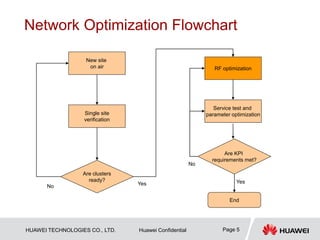
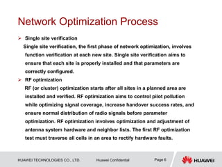
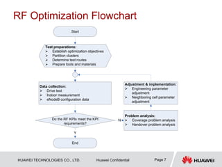
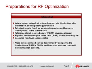
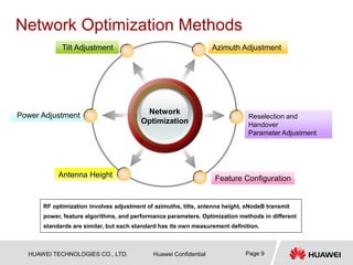
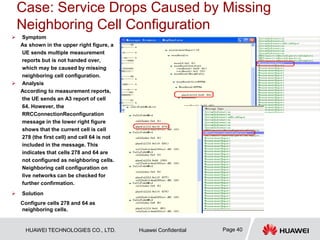
This document provides guidelines for LTE radio frequency (RF) network optimization. It describes the network optimization process including single site verification and RF optimization. Key aspects of RF optimization covered include preparing for optimization by collecting data, analyzing problems related to coverage, signal quality and handover success rate, and adjusting parameters like transmit power, antenna tilts and neighboring cell configurations. Common issues addressed are weak coverage, coverage holes, lack of a dominant cell, and cross coverage between cells. Optimization methods and specific cases are presented to resolve different problems.
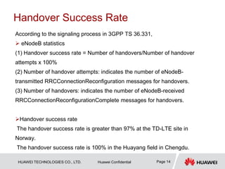
![HUAWEI TECHNOLOGIES CO., LTD. Huawei Confidential Page 12
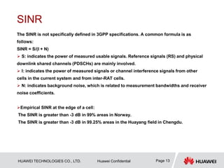
RSRP
Note: Different from GSM or TD-SCDMA systems, TD-LTE systems have multiple subcarriers multiplexed.
Therefore, the measured pilot signal strength is the RSRP of a single subcarrier (15 kHz) not the total
bandwidth power of the frequency.
The RSRPs near a cell, in the middle of a cell, and at the edge of a cell are determined based on the
distribution of signals on the entire network. Generally, the RSRP near a cell is -85 dBm, the RSRP in the
middle of a cell is -95 dBm, and the RSRP at the edge of a cell is -105 dBm.
Currently, the minimum RSRP for UEs to camp on a cell is -120 dBm.
Empirical RSRP at the edge of a cell:
The RSRP is greater than -110 dBm in 99% areas at the TD-LTE site in Norway.
The RSRP is greater than -110 dBm in 98.09% areas in the Huayang field in Chengdu.
Reference signal received power (RSRP), is determined for a
considered cell as the linear average over the power
contributions (in [W]) of the resource elements that carry cell-
specific reference signals within the considered measurement
frequency bandwidth.
3GPP
definition](https://image.slidesharecdn.com/lteoptimization-140704020734-phpapp01/85/Lte-optimization-12-320.jpg)


![54 gsm bss network performance ps kpi (rtt delay) optimization manual[1].doc](https://cdn.slidesharecdn.com/ss_thumbnails/54gsmbssnetworkperformancepskpirttdelayoptimizationmanual1-140618023530-phpapp01-thumbnail.jpg?width=640&height=640&fit=bounds)


![51 gsm bss network performance ps kpi (upload rate) optimization manual[1].doc](https://cdn.slidesharecdn.com/ss_thumbnails/51gsmbssnetworkperformancepskpiuploadrateoptimizationmanual1-140618023146-phpapp02-thumbnail.jpg?width=640&height=640&fit=bounds)
![50 gsm bss network ps kpi (download rate) optimization manual[1].doc](https://cdn.slidesharecdn.com/ss_thumbnails/50gsmbssnetworkpskpidownloadrateoptimizationmanual1-140618023140-phpapp01-thumbnail.jpg?width=640&height=640&fit=bounds)

![15 gsm bss network kpi (rx quality) optimization manual[1].doc](https://cdn.slidesharecdn.com/ss_thumbnails/15gsmbssnetworkkpirxqualityoptimizationmanual1-140618022506-phpapp01-thumbnail.jpg?width=640&height=640&fit=bounds)
![14 gsm bss network kpi (call setup time) optimization manual[1].doc](https://cdn.slidesharecdn.com/ss_thumbnails/14gsmbssnetworkkpicallsetuptimeoptimizationmanual1-140618022447-phpapp02-thumbnail.jpg?width=640&height=640&fit=bounds)
![13 gsm bss network kpi (network interference) optimization manual[1].doc](https://cdn.slidesharecdn.com/ss_thumbnails/13gsmbssnetworkkpinetworkinterferenceoptimizationmanual1-140618022430-phpapp01-thumbnail.jpg?width=640&height=640&fit=bounds)


![10 gsm bss network kpi (uplink downlink balance) optimization manual[1].doc](https://cdn.slidesharecdn.com/ss_thumbnails/10gsmbssnetworkkpiuplink-downlinkbalanceoptimizationmanual1-140618022209-phpapp01-thumbnail.jpg?width=640&height=640&fit=bounds)

