Download as PDF, PPTX

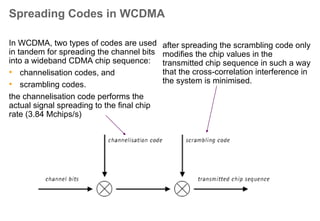
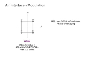
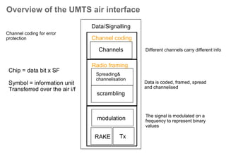
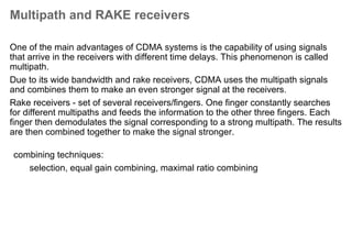

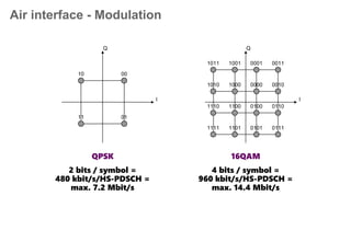
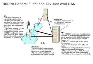
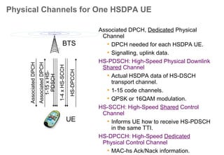
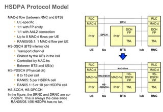

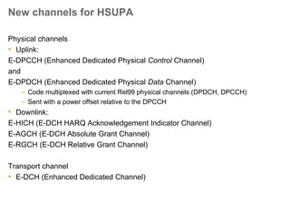
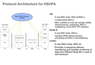
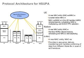

The document provides a comprehensive overview of the HSPA (High-Speed Packet Access) architecture and functionalities, including its support for WCDMA (Wideband Code Division Multiple Access) and HSDPA/HSUPA (High-Speed Downlink/Uplink Packet Access). It details the principles of channelization, spreading codes, modulation methods, and various types of channel coding and signal processing involved in optimizing data throughput and reducing latency. Additionally, it highlights the system's capacity for concurrent voice and data transmission, outlining the enhancements introduced in the architecture that boost performance in mobile communication networks.


![10 gsm bss network kpi (uplink downlink balance) optimization manual[1].doc](https://cdn.slidesharecdn.com/ss_thumbnails/10gsmbssnetworkkpiuplink-downlinkbalanceoptimizationmanual1-140618022209-phpapp01-thumbnail.jpg?width=640&height=640&fit=bounds)


