The document discusses SDCCH (Standalone Dedicated Control Channel) configuration and usage in GSM networks. It describes possible SDCCH configurations including SDCCH/8 and SDCCH/4. It also discusses SDCCH holding times for different functions, reasons for SDCCH congestion, and methods to prevent congestion through proper dimensioning of SDCCH resources.
In this document
Powered by AI
Overview of the presentation and introduction to the key concepts related to SDCCH.
Discusses SDCCH traffic estimations, causes and detection of congestion, and preventive measures.
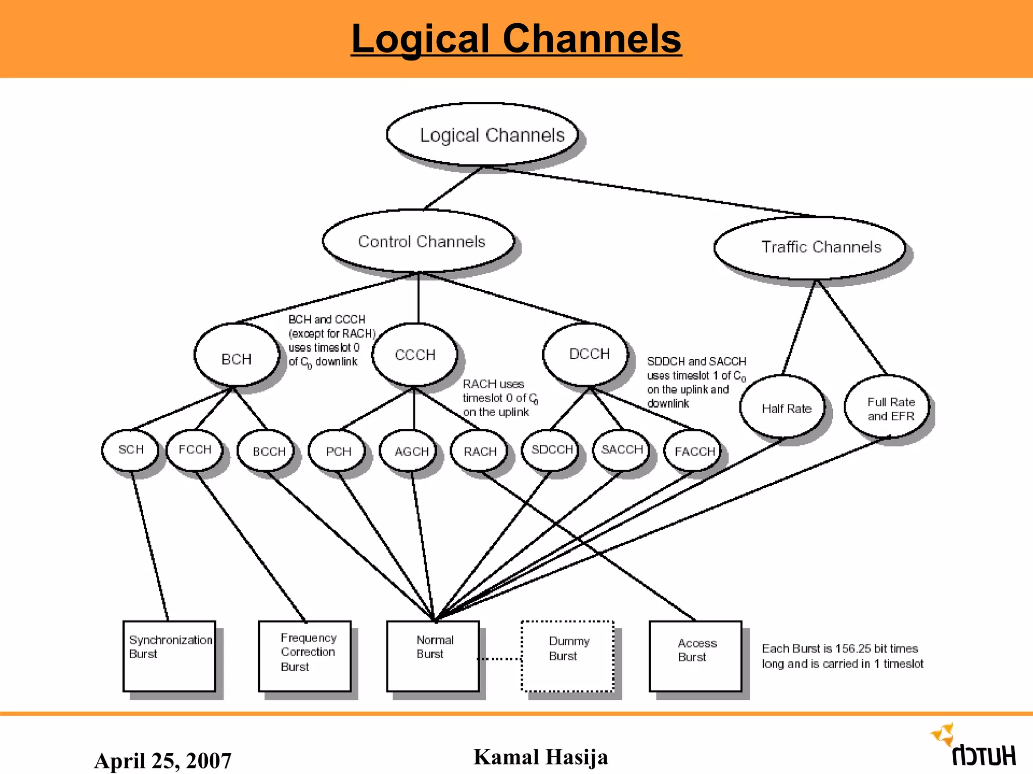
Details the types of logical channels, including Broadcast and Common Control Channels utilized in GSM.
Describes Dedicated Control Channels such as SDCCH, Slow and Fast Associated Control Channels.
Explains traffic channels in GSM, detailing the differences between Full Rate, Half Rate, and Enhanced channels.
Outlines various burst types including Normal, Frequency, Synchronization, Access, and Dummy Bursts.
Explains the mapping process of logical channels to physical channels for proper transmission.
Details the various usages of SDCCH in GSM networks and possible configurations to optimize performance.
Discusses SDCCH traffic estimations, causes and detection of congestion, and preventive measures.
Discusses methods to detect SDCCH congestion including symptoms and monitoring techniques.
Lists strategies to prevent SDCCH congestion, including optimal configurations and reducing unnecessary updates.
Describes the principle of SDCCH dimensioning, including configurations and load ratio assessments.
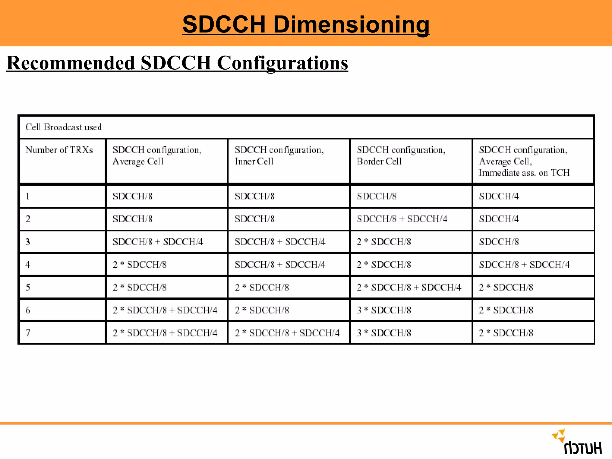
Presents recommended configurations for SDCCH to ensure efficient use of resources in GSM networks.
Overview of statistical counters and formulas used for evaluating SDCCH performance and traffic metrics.
Describes step-by-step procedures for mobile terminating call setups including authentication and assignment.
Contents April 25,2007 Channel Concepts Call Setup Burst & Multi Frames Mapping of Logical Channels Definitions of SDCCH Usage of SDCCH in the GSM network (BSC) Possible SDCCH Configuration SDCCH Holding Time Kamal Hasija
3.
Contents April 25.2007SDCCH Traffic Estimations SDCCH Congestion Reasons for SDCCH congestion How to detect SDCCH congestions Preventive actions to avoid SDCCH congestions SDCCH Dimensioning Parameters for SDCCH Dimensioning Counters & Report Analysis Kamal Hasija
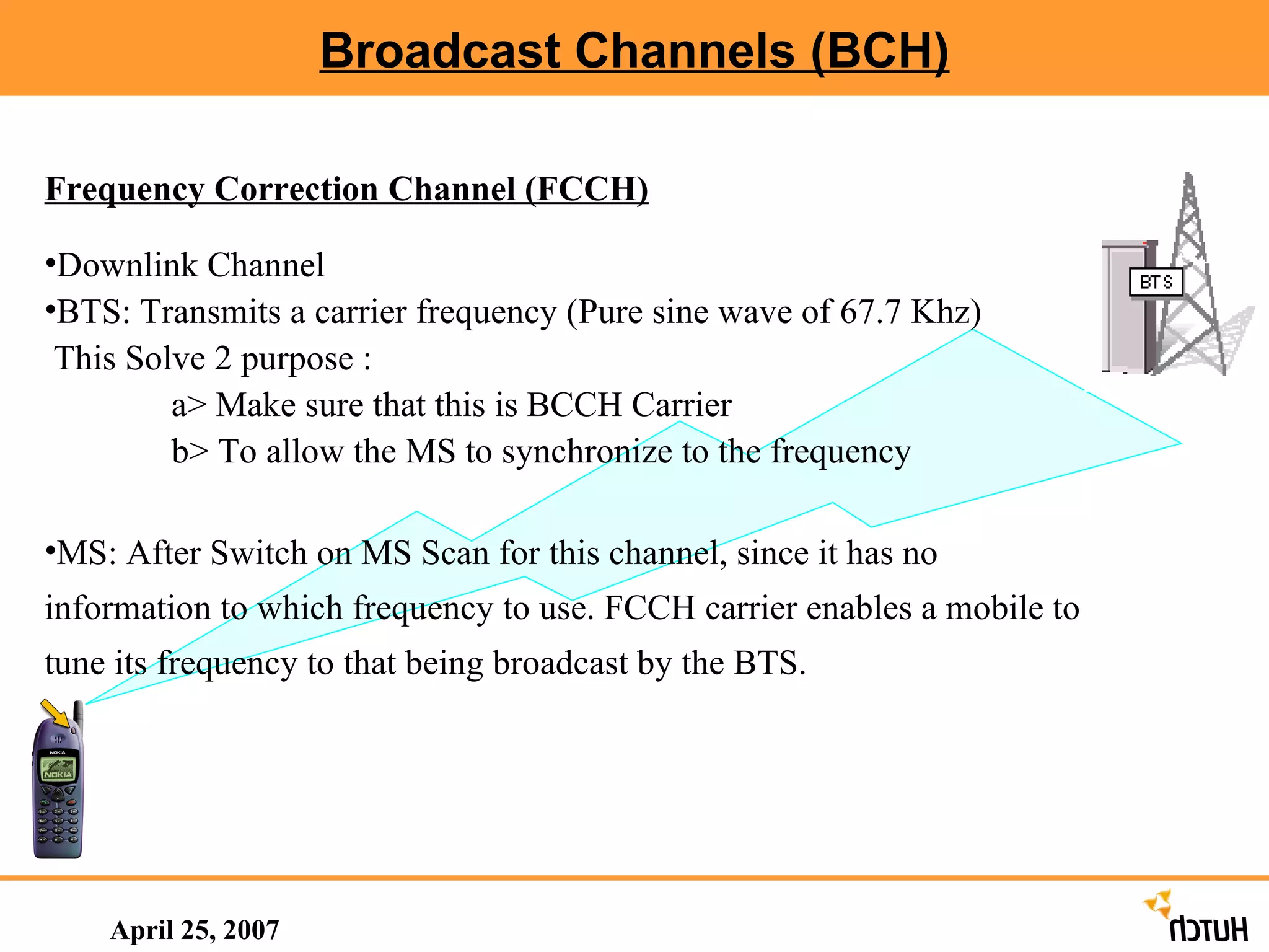
Broadcast Channels (BCH)April 25, 2007 Frequency Correction Channel (FCCH) Downlink Channel BTS: Transmits a carrier frequency (Pure sine wave of 67.7 Khz) This Solve 2 purpose : a> Make sure that this is BCCH Carrier b> To allow the MS to synchronize to the frequency MS: After Switch on MS Scan for this channel, since it has no information to which frequency to use. FCCH carrier enables a mobile to tune its frequency to that being broadcast by the BTS.
6.
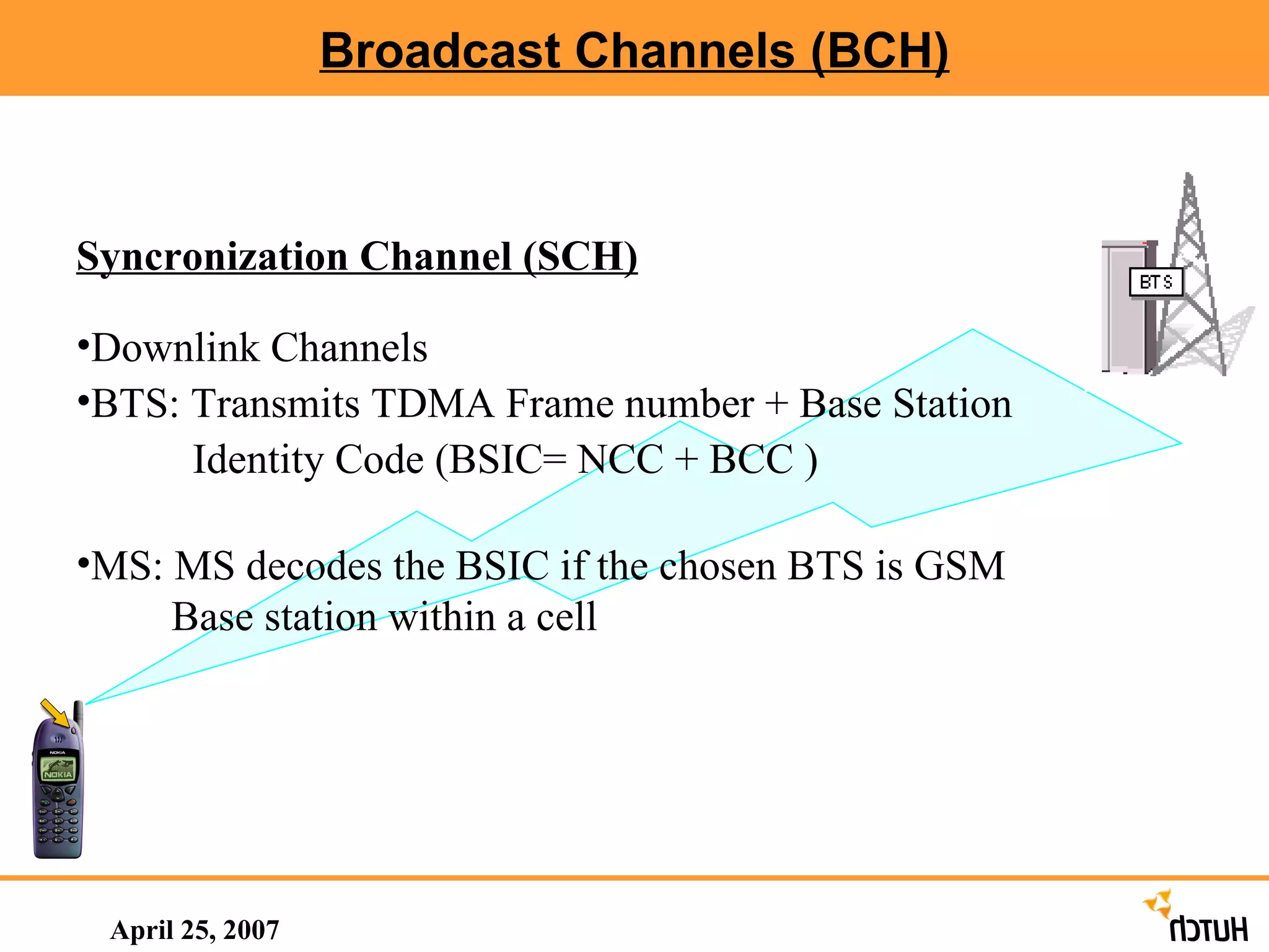
Broadcast Channels (BCH)April 25, 2007 Syncronization Channel (SCH) Downlink Channels BTS: Transmits TDMA Frame number + Base Station Identity Code (BSIC= NCC + BCC ) MS: MS decodes the BSIC if the chosen BTS is GSM Base station within a cell
7.
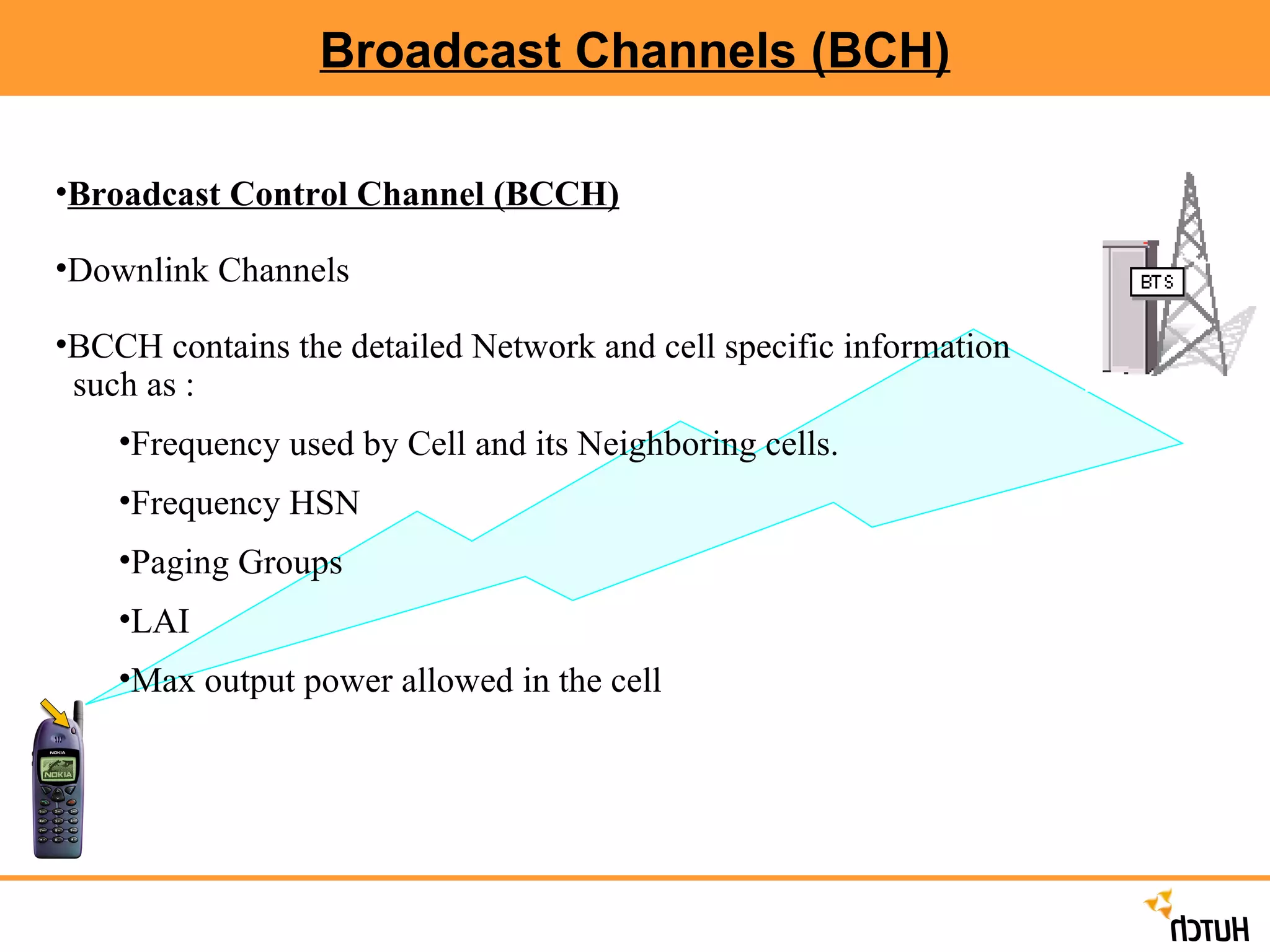
Broadcast Channels (BCH)Broadcast Control Channel (BCCH) Downlink Channels BCCH contains the detailed Network and cell specific information such as : Frequency used by Cell and its Neighboring cells. Frequency HSN Paging Groups LAI Max output power allowed in the cell
8.
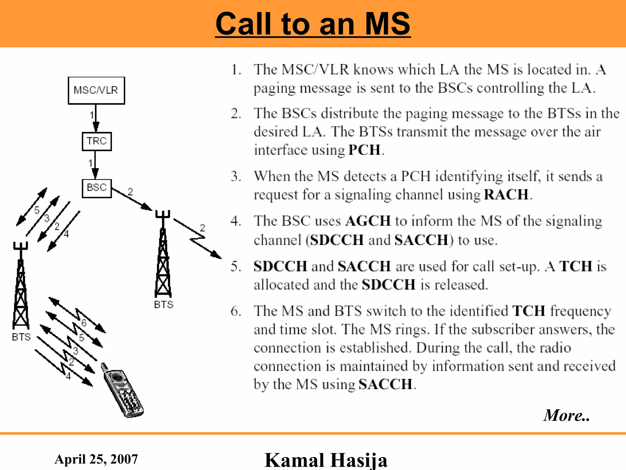
Common Control Channels(CCCH) Paging Channel (PCH) Downlink Channels BTS: Broadcast the paging message to indicate the Incoming Calls or Incoming SMS. Paging message also includes the MS’s identity number IMSI/TMSI MS: MS listens to the PCH. If it identifies its own mobile subscriber identity number on the PCH, it will respond.
9.
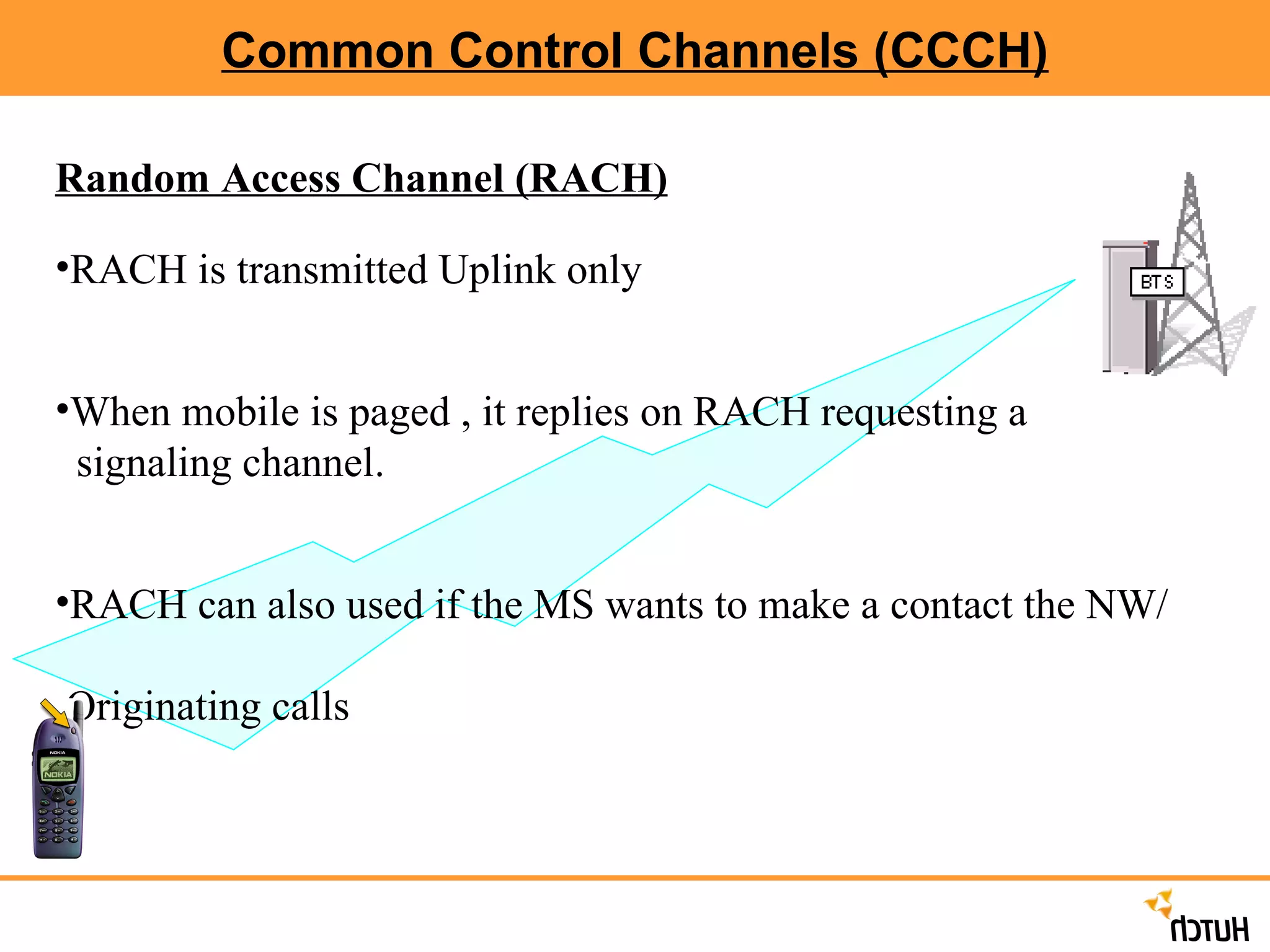
Common Control Channels(CCCH) Random Access Channel (RACH) RACH is transmitted Uplink only When mobile is paged , it replies on RACH requesting a signaling channel. RACH can also used if the MS wants to make a contact the NW/ Originating calls
10.
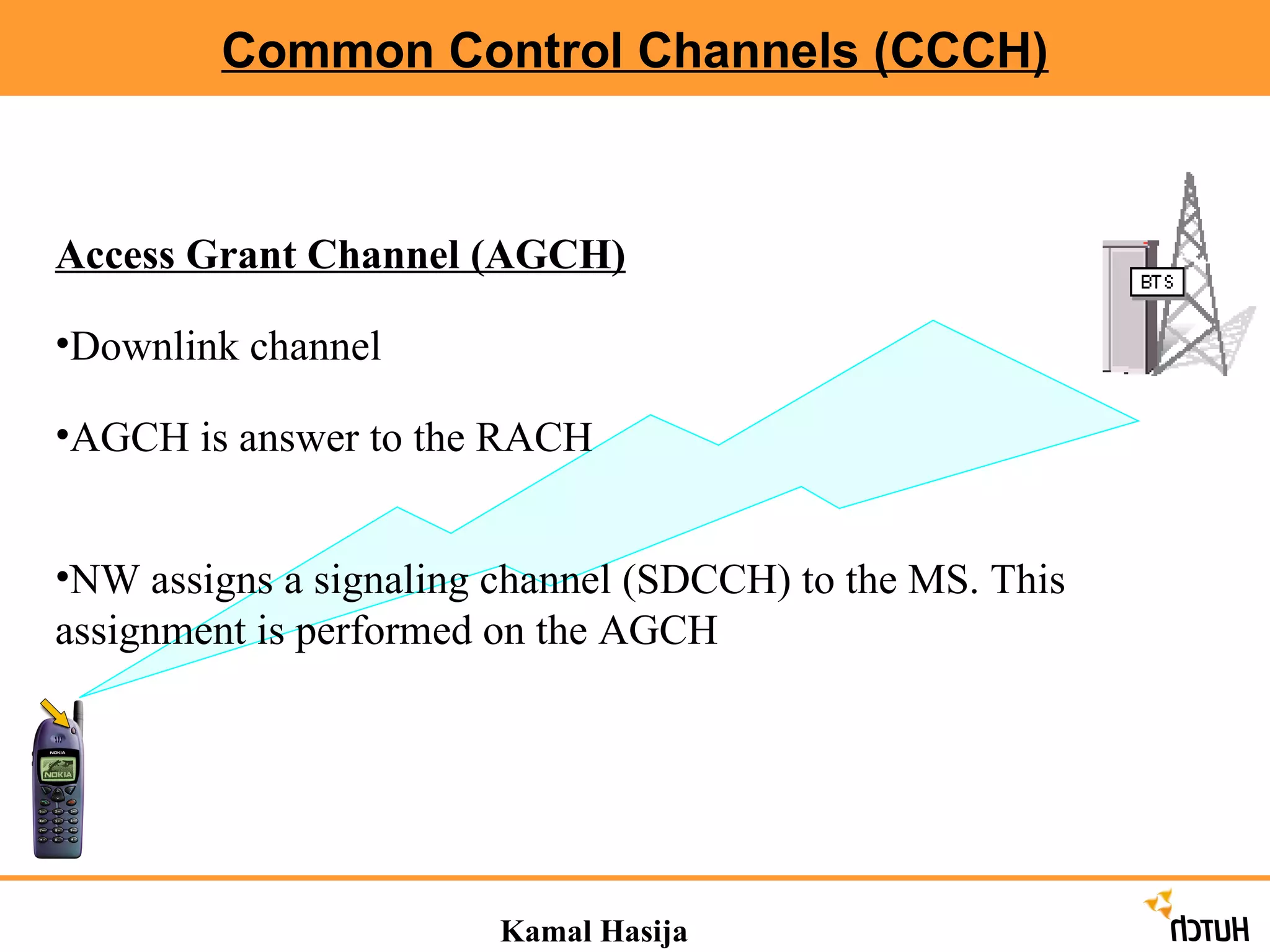
Common Control Channels(CCCH) Kamal Hasija Access Grant Channel (AGCH) Downlink channel AGCH is answer to the RACH NW assigns a signaling channel (SDCCH) to the MS. This assignment is performed on the AGCH
11.
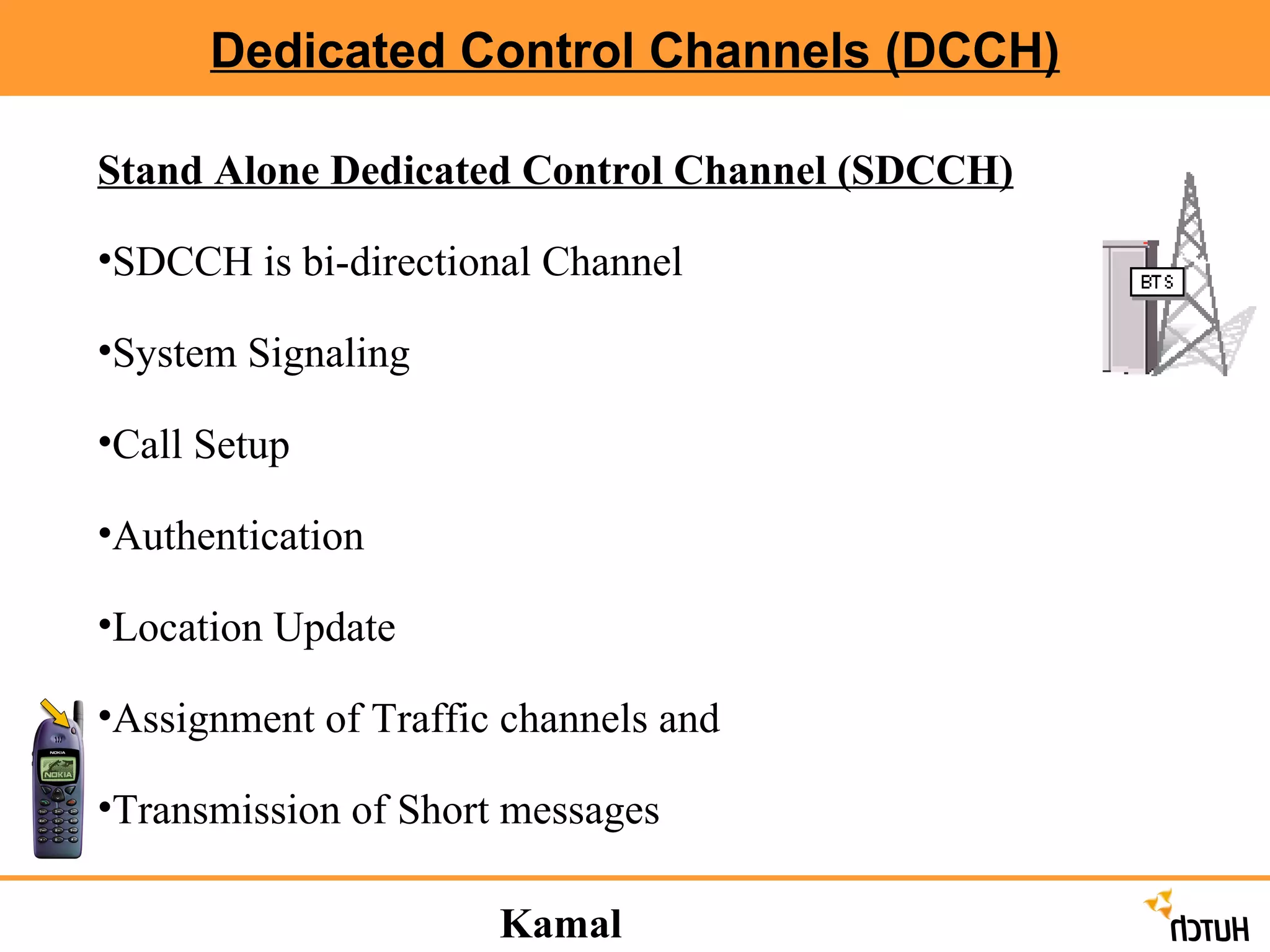
Dedicated Control Channels(DCCH) Stand Alone Dedicated Control Channel (SDCCH) SDCCH is bi-directional Channel System Signaling Call Setup Authentication Location Update Assignment of Traffic channels and Transmission of Short messages Kamal Hasija
12.
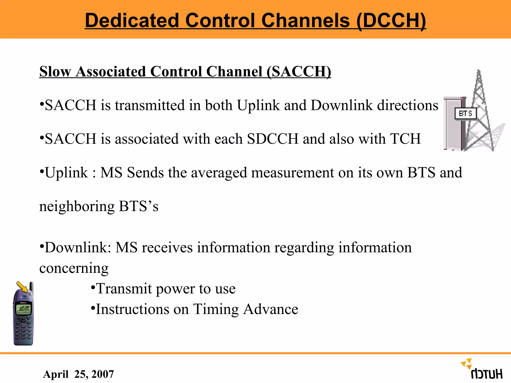
Dedicated Control Channels(DCCH) April 25, 2007 Slow Associated Control Channel (SACCH) SACCH is transmitted in both Uplink and Downlink directions SACCH is associated with each SDCCH and also with TCH Uplink : MS Sends the averaged measurement on its own BTS and neighboring BTS’s Downlink: MS receives information regarding information concerning Transmit power to use Instructions on Timing Advance
13.
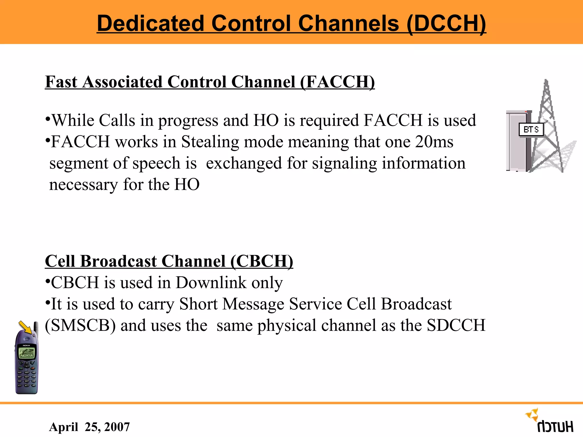
Dedicated Control Channels(DCCH) April 25, 2007 Fast Associated Control Channel (FACCH) While Calls in progress and HO is required FACCH is used FACCH works in Stealing mode meaning that one 20ms segment of speech is exchanged for signaling information necessary for the HO Cell Broadcast Channel (CBCH) CBCH is used in Downlink only It is used to carry Short Message Service Cell Broadcast (SMSCB) and uses the same physical channel as the SDCCH
14.
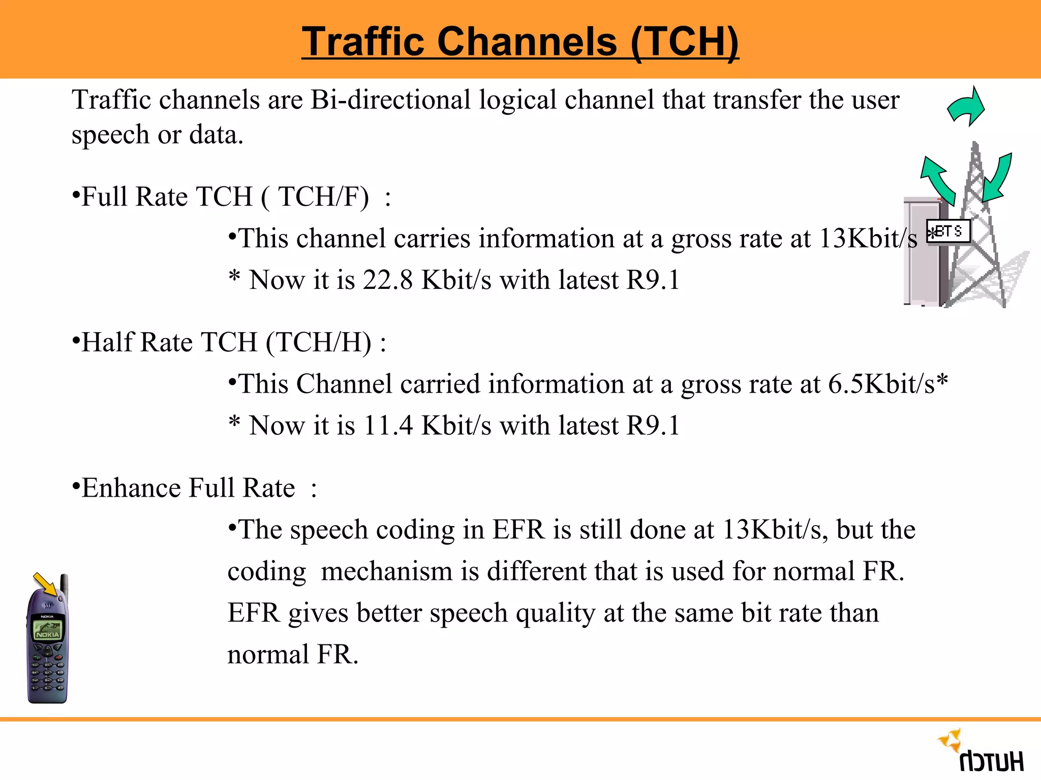
Traffic Channels (TCH)Traffic channels are Bi-directional logical channel that transfer the user speech or data. Full Rate TCH ( TCH/F) : This channel carries information at a gross rate at 13Kbit/s * * Now it is 22.8 Kbit/s with latest R9.1 Half Rate TCH (TCH/H) : This Channel carried information at a gross rate at 6.5Kbit/s* * Now it is 11.4 Kbit/s with latest R9.1 Enhance Full Rate : The speech coding in EFR is still done at 13Kbit/s, but the coding mechanism is different that is used for normal FR. EFR gives better speech quality at the same bit rate than normal FR.
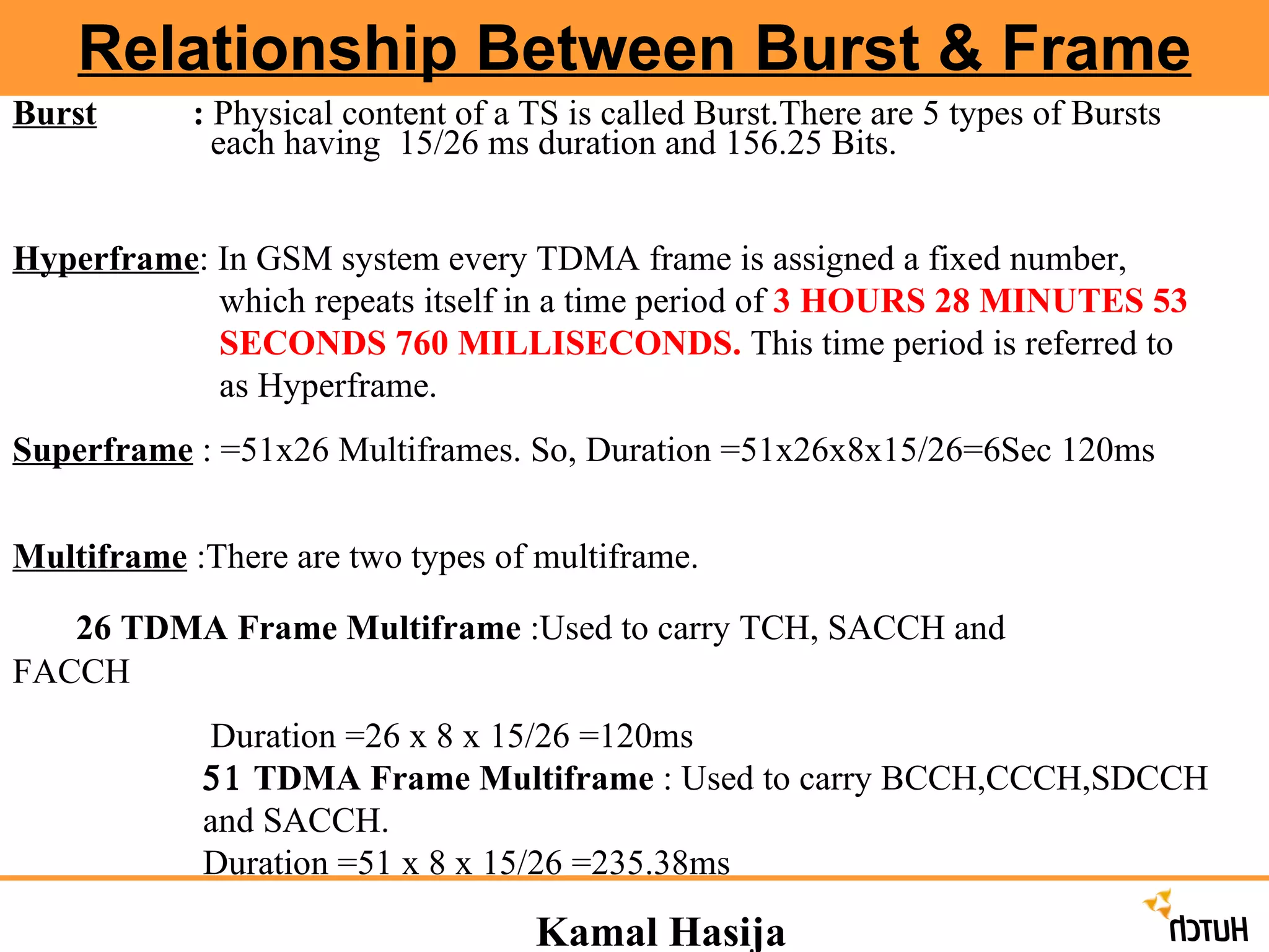
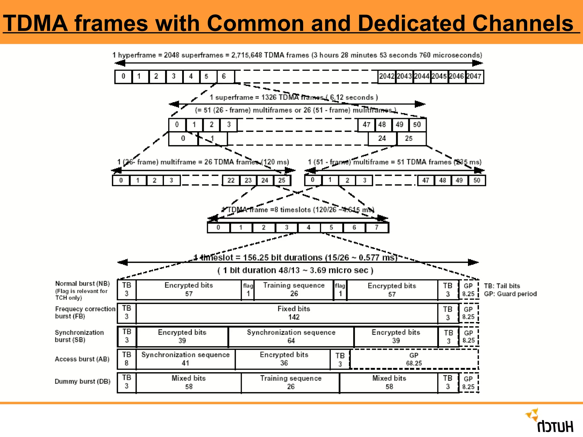
Kamal Hasija RelationshipBetween Burst & Frame Burst : Physical content of a TS is called Burst.There are 5 types of Bursts each having 15/26 ms duration and 156.25 Bits. Hyperframe : In GSM system every TDMA frame is assigned a fixed number, which repeats itself in a time period of 3 HOURS 28 MINUTES 53 SECONDS 760 MILLISECONDS. This time period is referred to as Hyperframe. Superframe : =51x26 Multiframes. So, Duration =51x26x8x15/26=6Sec 120ms Multiframe :There are two types of multiframe. 26 TDMA Frame Multiframe :Used to carry TCH, SACCH and FACCH Duration =26 x 8 x 15/26 =120ms TDMA Frame Multiframe : Used to carry BCCH,CCCH,SDCCH and SACCH. Duration =51 x 8 x 15/26 =235.38ms
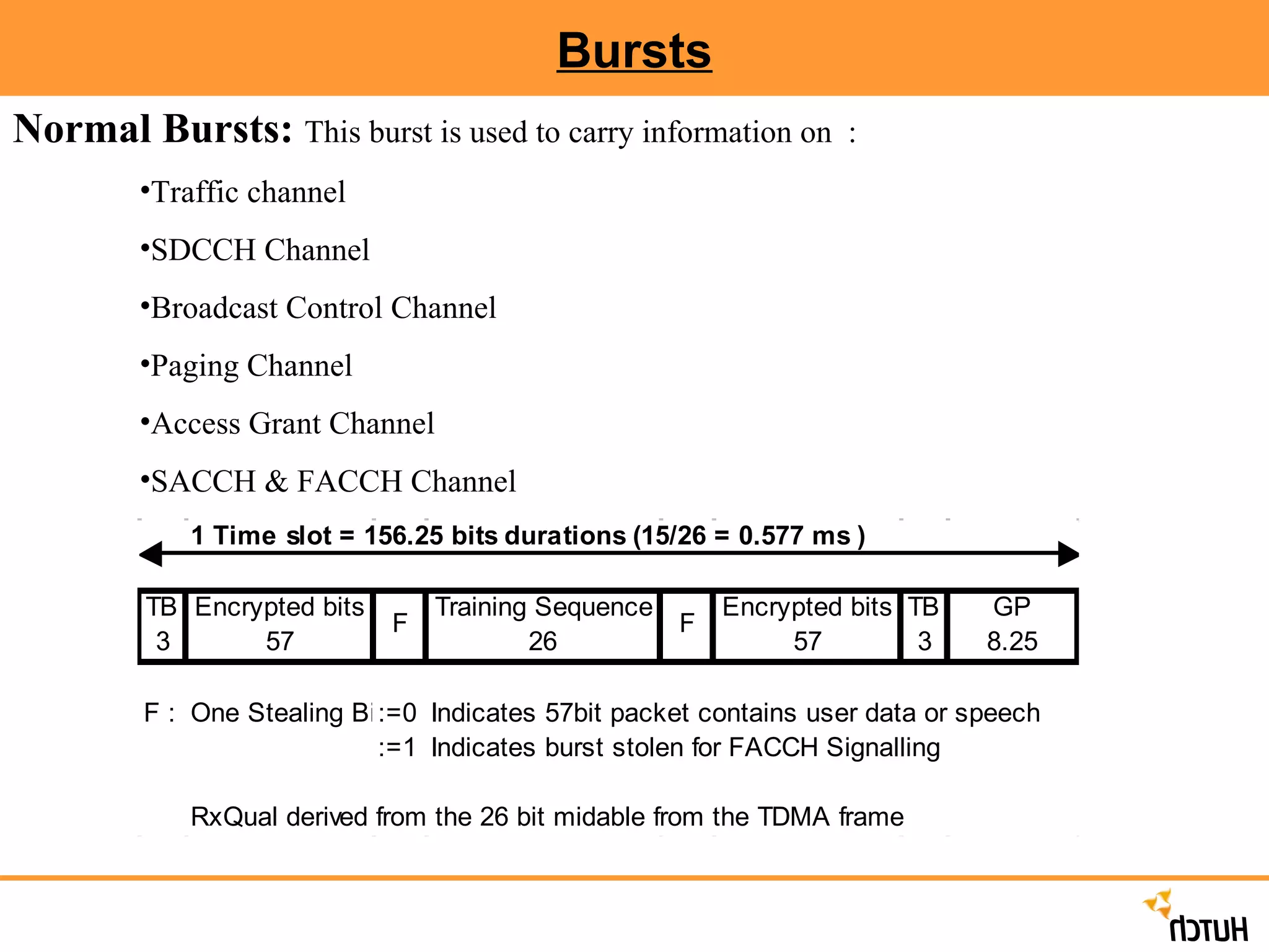
Bursts Normal Bursts: This burst is used to carry information on : Traffic channel SDCCH Channel Broadcast Control Channel Paging Channel Access Grant Channel SACCH & FACCH Channel
19.
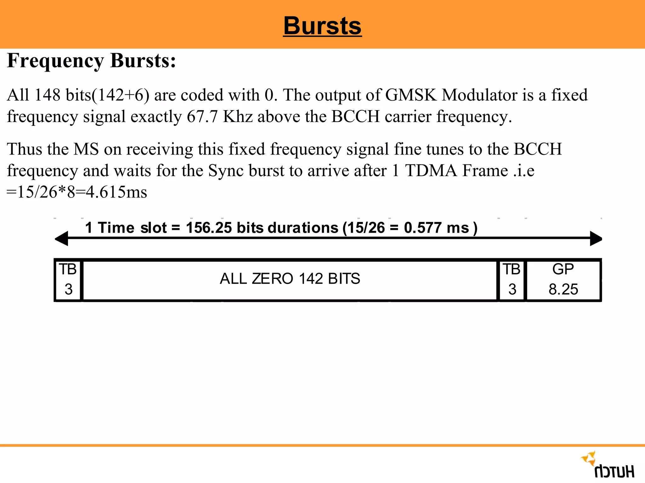
Bursts Frequency Bursts: All 148 bits(142+6) are coded with 0. The output of GMSK Modulator is a fixed frequency signal exactly 67.7 Khz above the BCCH carrier frequency. Thus the MS on receiving this fixed frequency signal fine tunes to the BCCH frequency and waits for the Sync burst to arrive after 1 TDMA Frame .i.e =15/26*8=4.615ms
20.
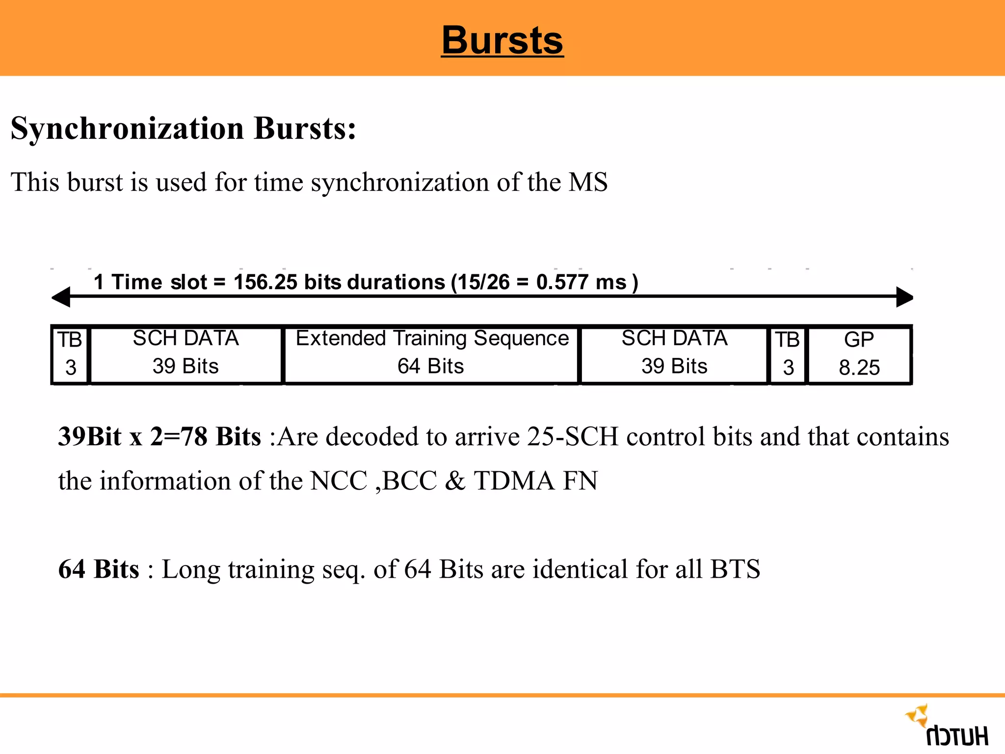
Bursts Synchronization Bursts: This burst is used for time synchronization of the MS 39Bit x 2=78 Bits :Are decoded to arrive 25-SCH control bits and that contains the information of the NCC ,BCC & TDMA FN 64 Bits : Long training seq. of 64 Bits are identical for all BTS
21.
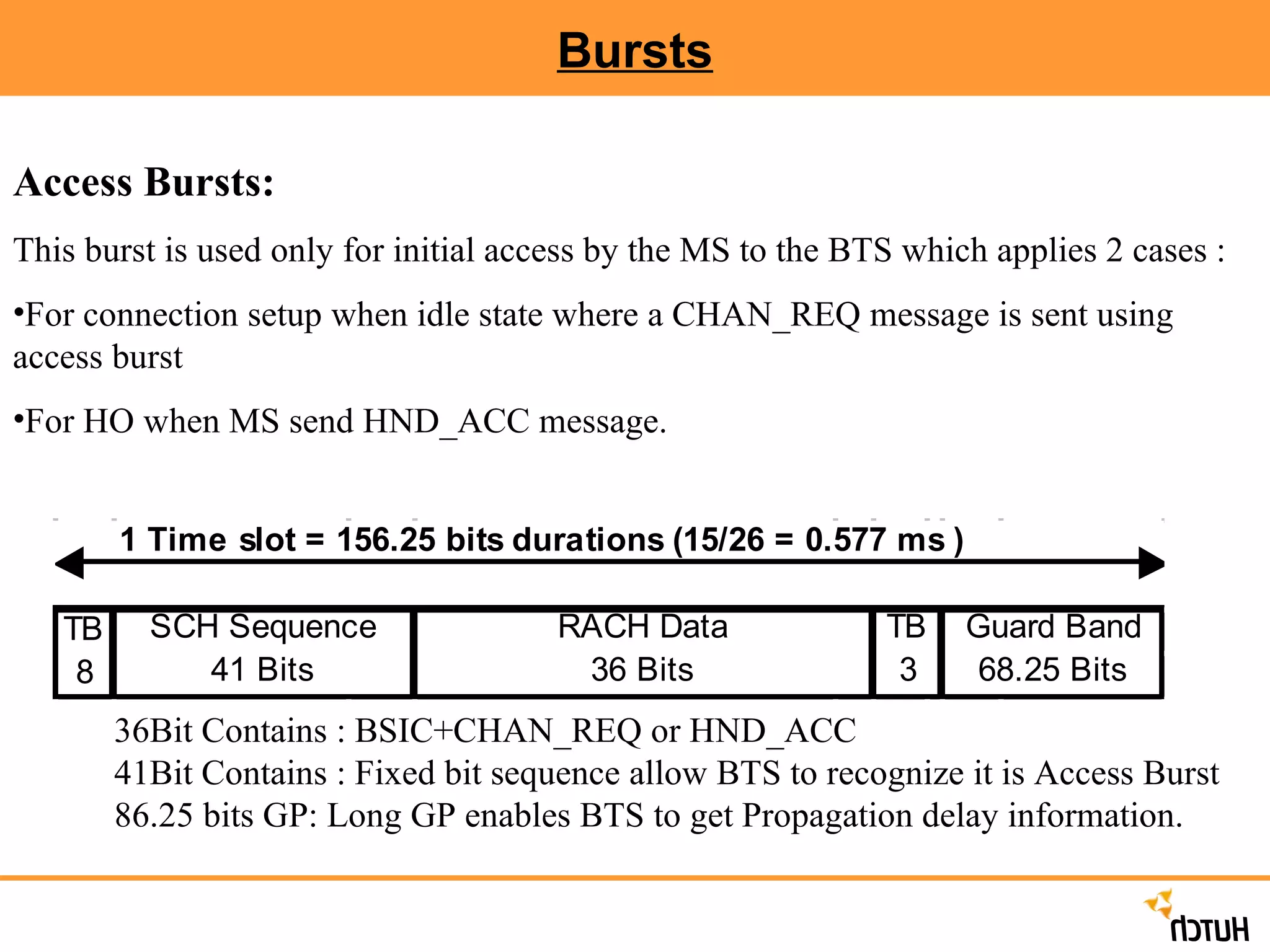
Bursts Access Bursts: This burst is used only for initial access by the MS to the BTS which applies 2 cases : For connection setup when idle state where a CHAN_REQ message is sent using access burst For HO when MS send HND_ACC message. 36Bit Contains : BSIC+CHAN_REQ or HND_ACC 41Bit Contains : Fixed bit sequence allow BTS to recognize it is Access Burst 86.25 bits GP: Long GP enables BTS to get Propagation delay information.
22.
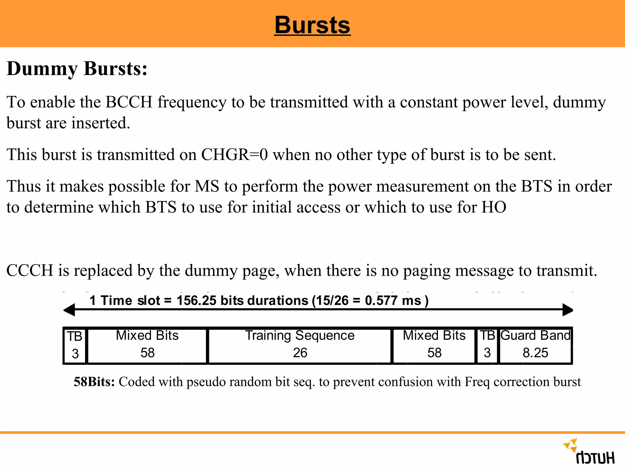
Bursts Dummy Bursts: To enable the BCCH frequency to be transmitted with a constant power level, dummy burst are inserted. This burst is transmitted on CHGR=0 when no other type of burst is to be sent. Thus it makes possible for MS to perform the power measurement on the BTS in order to determine which BTS to use for initial access or which to use for HO CCCH is replaced by the dummy page, when there is no paging message to transmit. 58Bits: Coded with pseudo random bit seq. to prevent confusion with Freq correction burst
23.
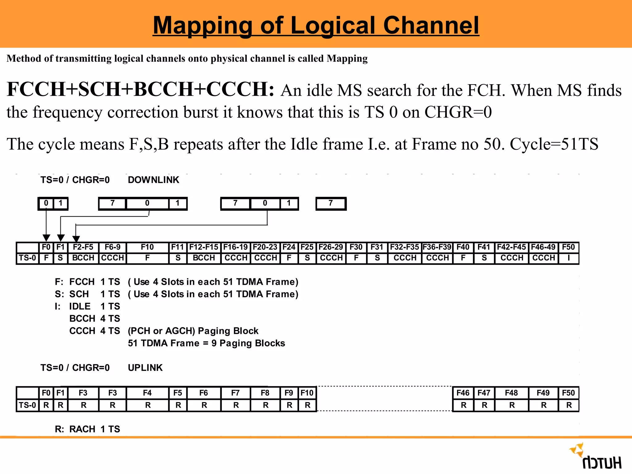
Mapping of LogicalChannel Method of transmitting logical channels onto physical channel is called Mapping FCCH+SCH+BCCH+CCCH: An idle MS search for the FCH. When MS finds the frequency correction burst it knows that this is TS 0 on CHGR=0 The cycle means F,S,B repeats after the Idle frame I.e. at Frame no 50. Cycle=51TS
24.
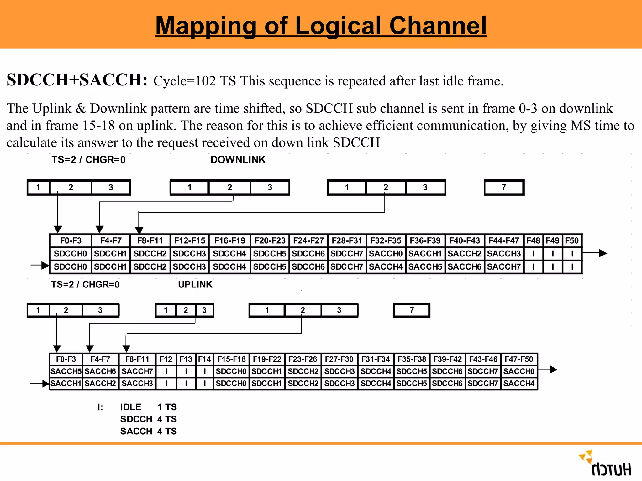
Mapping of LogicalChannel SDCCH+SACCH: Cycle=102 TS This sequence is repeated after last idle frame. The Uplink & Downlink pattern are time shifted, so SDCCH sub channel is sent in frame 0-3 on downlink and in frame 15-18 on uplink. The reason for this is to achieve efficient communication, by giving MS time to calculate its answer to the request received on down link SDCCH
25.
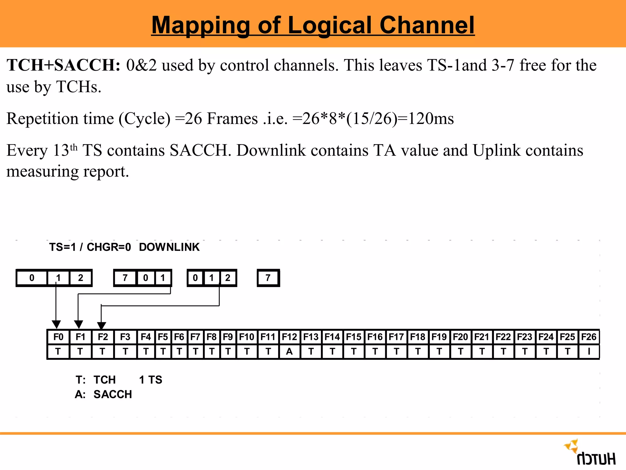
Mapping of LogicalChannel TCH+SACCH: 0&2 used by control channels. This leaves TS-1and 3-7 free for the use by TCHs. Repetition time (Cycle) =26 Frames .i.e. =26*8*(15/26)=120ms Every 13 th TS contains SACCH. Downlink contains TA value and Uplink contains measuring report.
26.
Usage of SDCCHThe SDCCH are used in some different ways in the GSM network: Registrations: Periodic Location Updates, IMSI Attach/Detach Call Setup: Immediate Assignment -> Assignment. SMS point-to-point: SMS messages to/from MS in Idle mode. Fax Setup Optional: USSD (Unstructured Supplementary Service Data) data transfer. MS<->Network. Similar to SMS. Controlled by the MSC.
27.
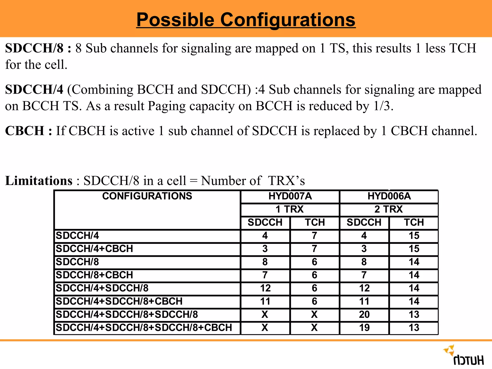
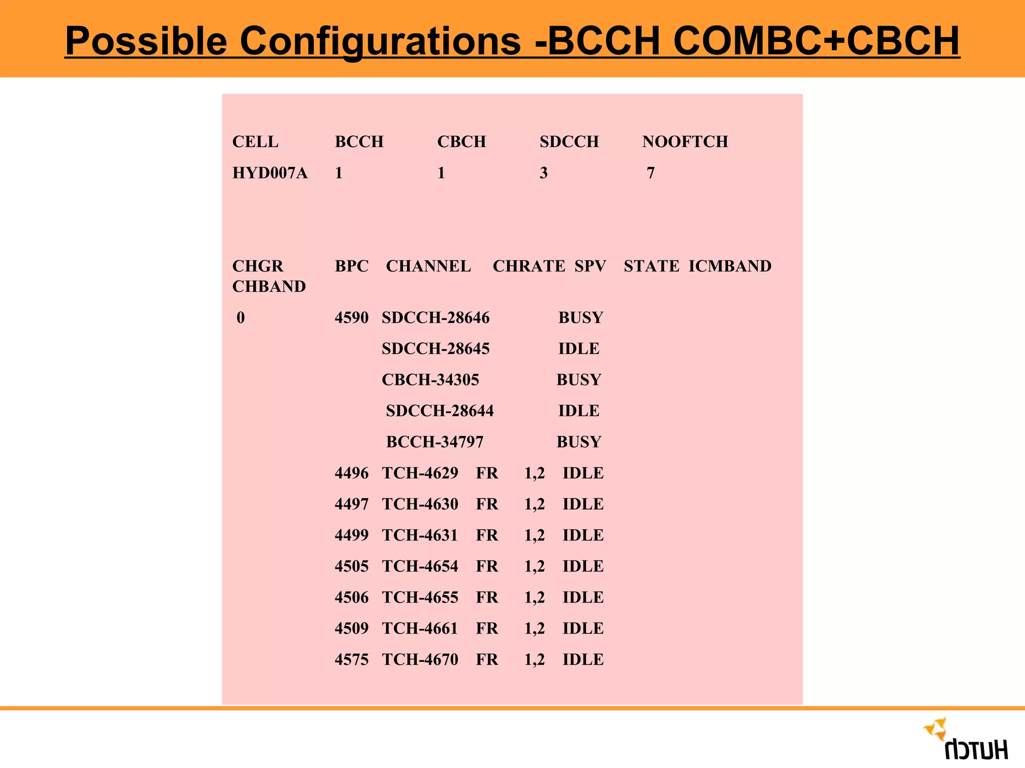
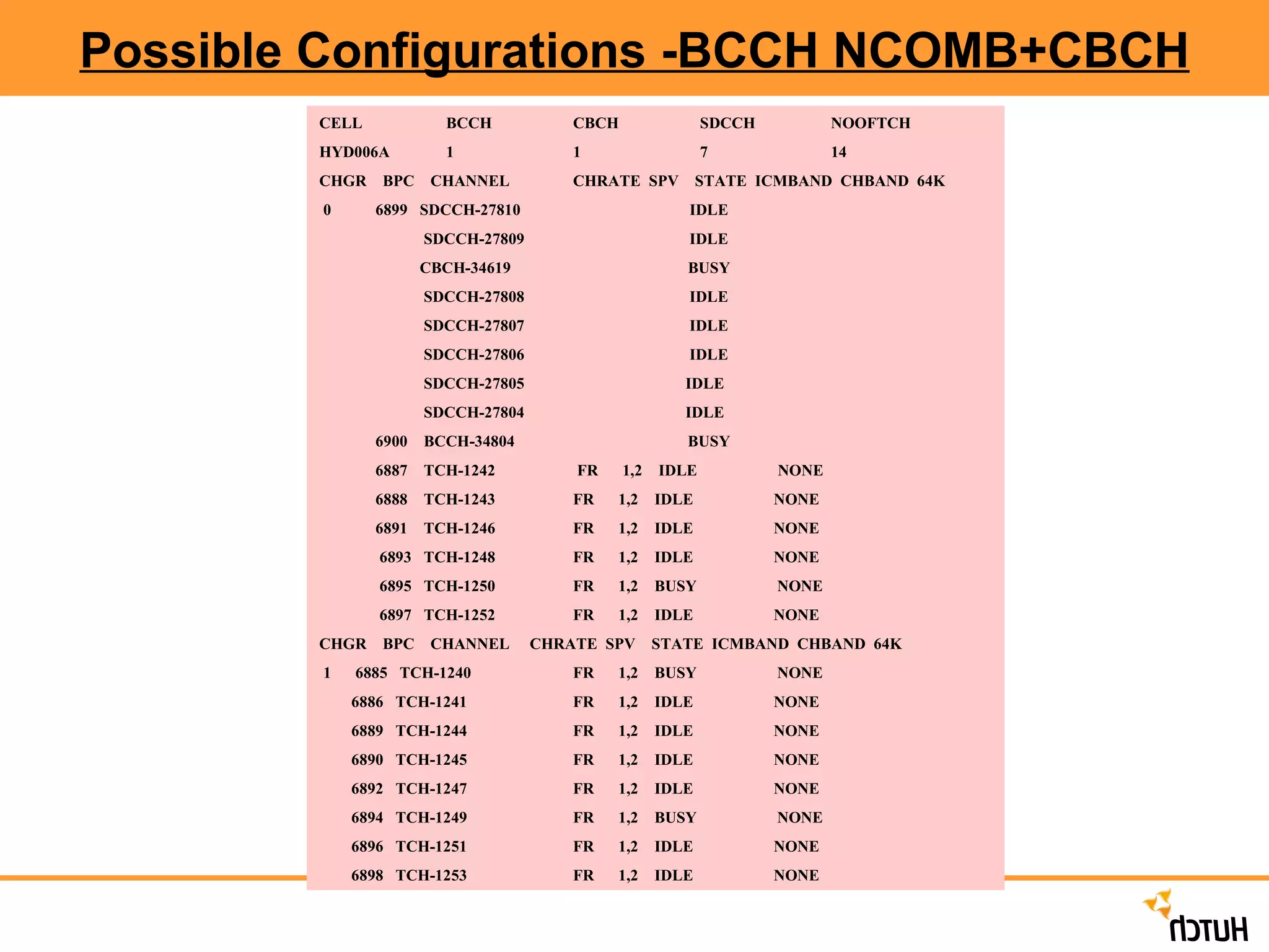
Possible Configurations SDCCH/8: 8 Sub channels for signaling are mapped on 1 TS, this results 1 less TCH for the cell. SDCCH/4 (Combining BCCH and SDCCH) :4 Sub channels for signaling are mapped on BCCH TS. As a result Paging capacity on BCCH is reduced by 1/3. CBCH : If CBCH is active 1 sub channel of SDCCH is replaced by 1 CBCH channel. Limitations : SDCCH/8 in a cell = Number of TRX’s
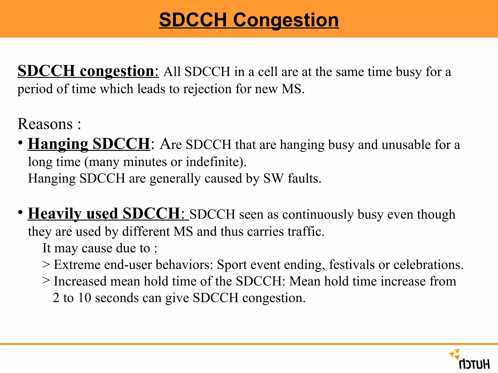
SDCCH Congestion SDCCHcongestion : All SDCCH in a cell are at the same time busy for a period of time which leads to rejection for new MS. Reasons : Hanging SDCCH : A re SDCCH that are hanging busy and unusable for a long time (many minutes or indefinite). Hanging SDCCH are generally caused by SW faults. Heavily used SDCCH : SDCCH seen as continuously busy even though they are used by different MS and thus carries traffic. It may cause due to : > Extreme end-user behaviors: Sport event ending, festivals or celebrations. Increased mean hold time of the SDCCH: Mean hold time increase from 2 to 10 seconds can give SDCCH congestion.
31.
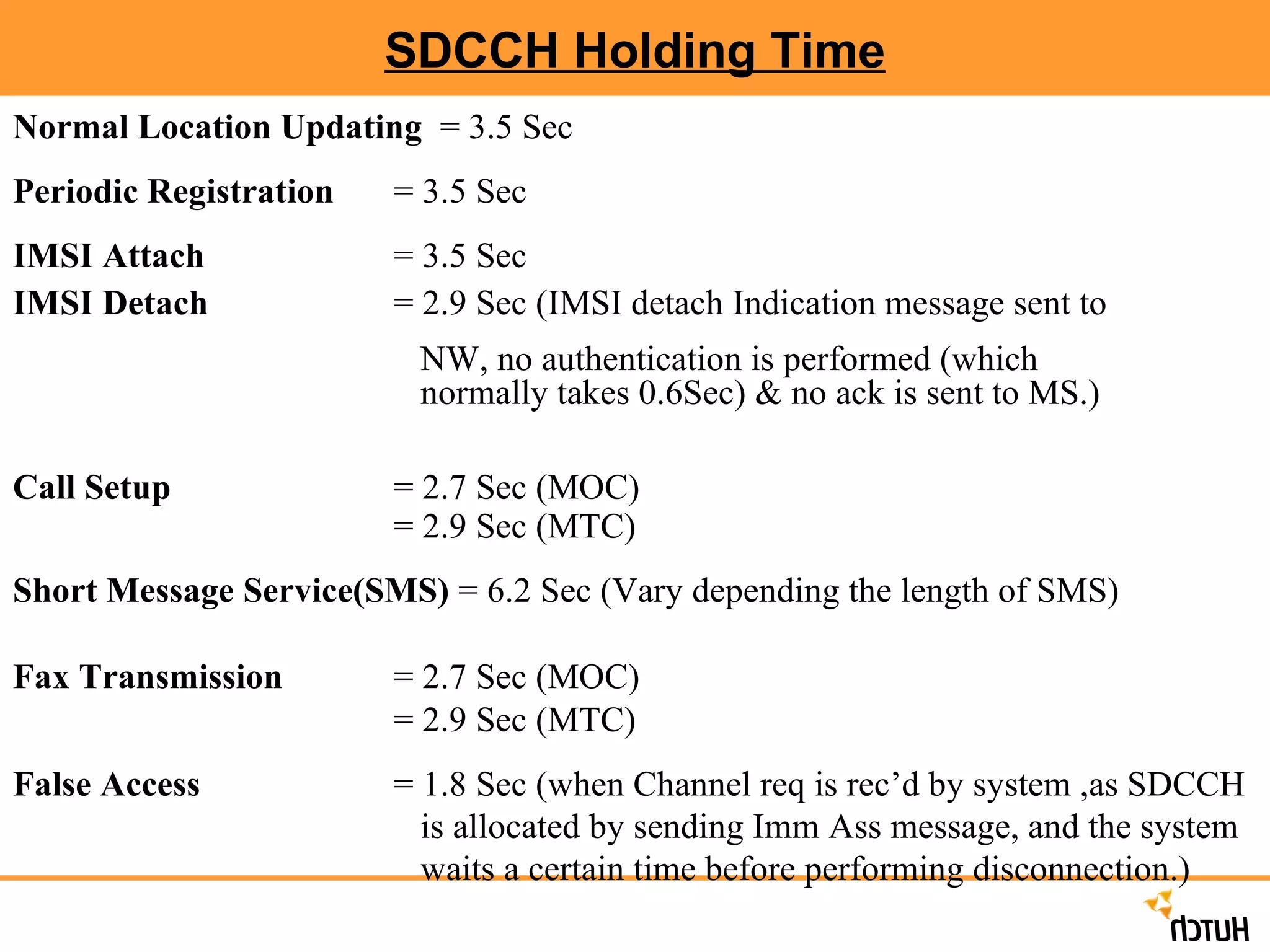
SDCCH Holding TimeNormal Location Updating = 3.5 Sec Periodic Registration = 3.5 Sec IMSI Attach = 3.5 Sec IMSI Detach = 2.9 Sec (IMSI detach Indication message sent to NW, no authentication is performed (which normally takes 0.6Sec) & no ack is sent to MS.) Call Setup = 2.7 Sec (MOC) = 2.9 Sec (MTC) Short Message Service(SMS) = 6.2 Sec (Vary depending the length of SMS) Fax Transmission = 2.7 Sec (MOC) = 2.9 Sec (MTC) False Access = 1.8 Sec (when Channel req is rec’d by system ,as SDCCH is allocated by sending Imm Ass message, and the system waits a certain time before performing disconnection.)
32.
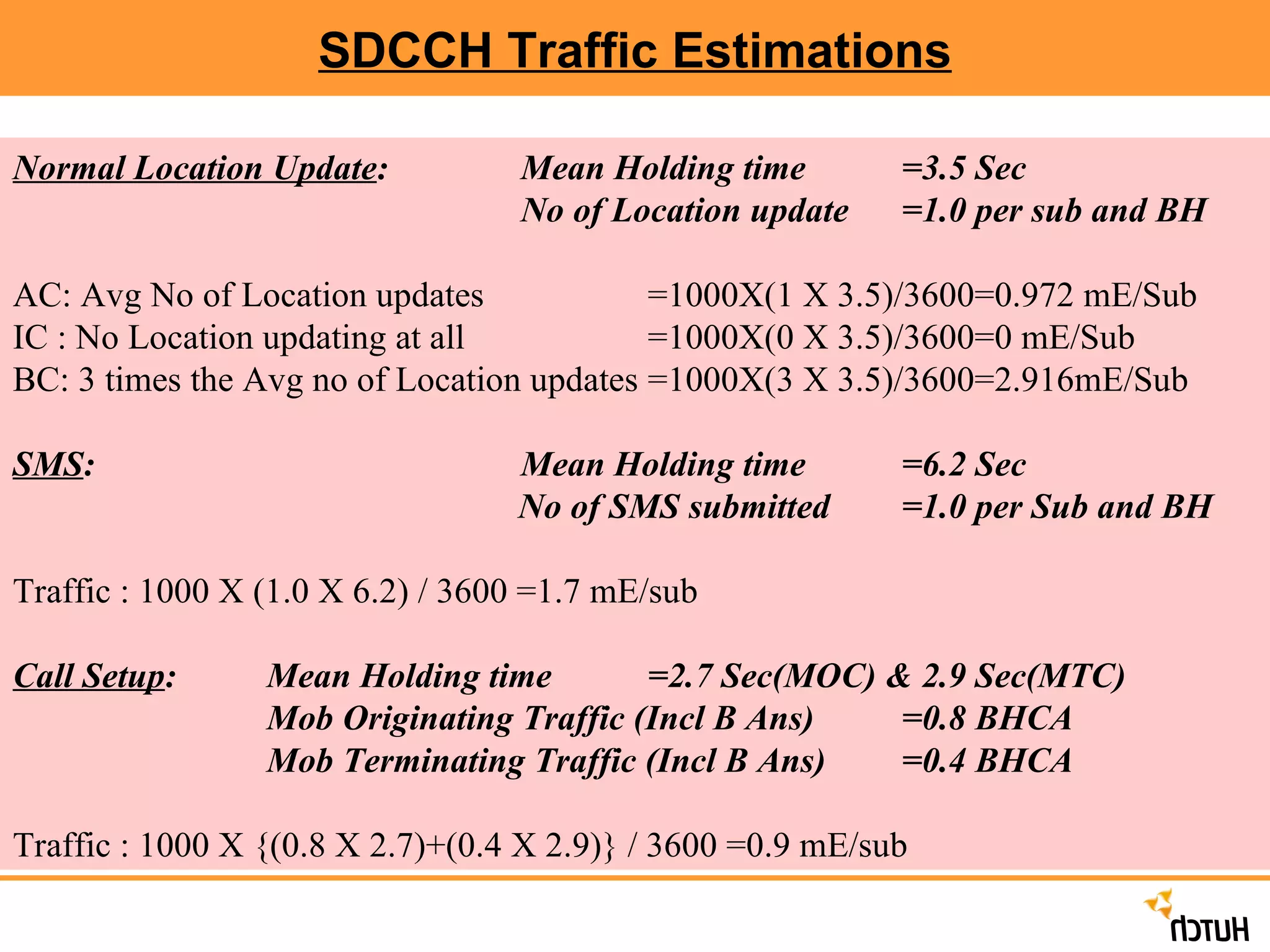
SDCCH Traffic EstimationsNormal Location Update : Mean Holding time =3.5 Sec No of Location update =1.0 per sub and BH AC: Avg No of Location updates =1000X(1 X 3.5)/3600=0.972 mE/Sub IC : No Location updating at all =1000X(0 X 3.5)/3600=0 mE/Sub BC: 3 times the Avg no of Location updates =1000X(3 X 3.5)/3600=2.916mE/Sub SMS : Mean Holding time =6.2 Sec No of SMS submitted =1.0 per Sub and BH Traffic : 1000 X (1.0 X 6.2) / 3600 =1.7 mE/sub Call Setup : Mean Holding time =2.7 Sec(MOC) & 2.9 Sec(MTC) Mob Originating Traffic (Incl B Ans) =0.8 BHCA Mob Terminating Traffic (Incl B Ans) =0.4 BHCA Traffic : 1000 X {(0.8 X 2.7)+(0.4 X 2.9)} / 3600 =0.9 mE/sub
33.
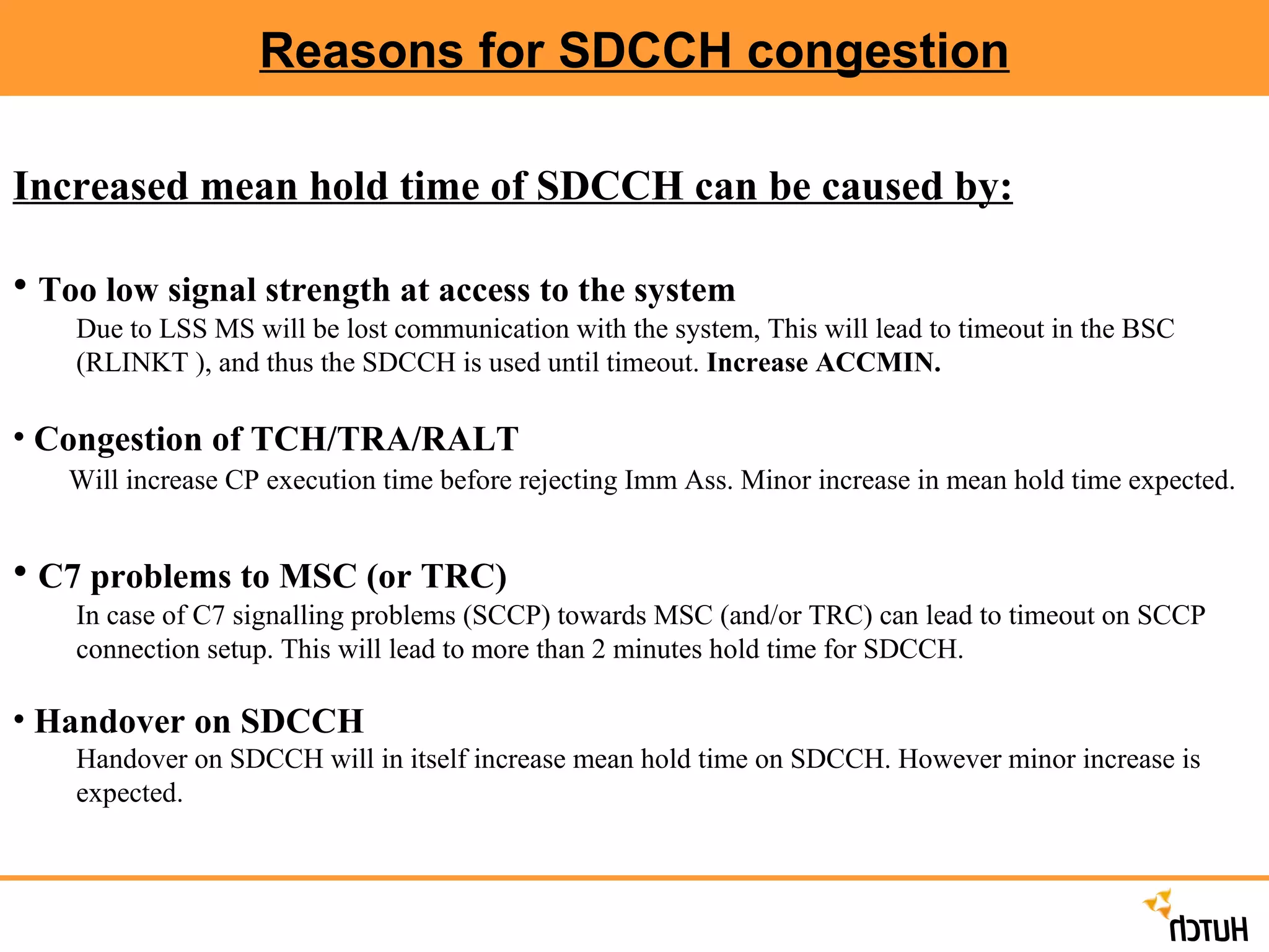
Reasons for SDCCHcongestion Increased mean hold time of SDCCH can be caused by: Too low signal strength at access to the system Due to LSS MS will be lost communication with the system, This will lead to timeout in the BSC (RLINKT ), and thus the SDCCH is used until timeout. Increase ACCMIN. Congestion of TCH/TRA/RALT Will increase CP execution time before rejecting Imm Ass. Minor increase in mean hold time expected. C7 problems to MSC (or TRC) In case of C7 signalling problems (SCCP) towards MSC (and/or TRC) can lead to timeout on SCCP connection setup. This will lead to more than 2 minutes hold time for SDCCH. Handover on SDCCH Handover on SDCCH will in itself increase mean hold time on SDCCH. However minor increase is expected.
34.
Reasons for SDCCHcongestion Congestion on Air-interface Congestion on Air-interface leads to delay in communication to the MS. Can give timeout in BSC during Imm Ass.Increases SDCCH mean hold time with more than 2 seconds. Congestion on Abis (LAPD link) Congestion on Abis leads to delay in communication with BTS and MS. Can give timeout in BSC during channel activation (TCHACTIVE). Increase SDCCH mean hold time with more than 5 seconds.. Congestion on A-interface Congestion on the A-interface will lead to increased mean hold time on SDCCH. Increase is unknown. High load in MSC/VLR or HLR High load in MSC/VLR and/or HLR will lead to increased mean hold time on SDCCH. Increase is unknown.
35.
How to detectSDCCH congestion in the BSC There is no good way to detect SDCCH congestion in real time in the BSC! A number of symptoms to look for: Increased CP Load. Decreased usage of TRA devices. Location Updates fails => Mobile terminating calls does not reach the subscriber. Subscriber complaints. Can not access the system. STS counters . Object type: CLSDCCH and CLSDCCHO. Seizure Supervision of LCHs (but only for Hanging SDCCHs!)
36.
Preventive actions toavoid SDCCH congestion Avoid combined BCCH in cells with many SDCCHs Use the optional feature Adaptive Configuration of SDCCHs (ACLC) Use USSD (Unstructured Supplementary Service data) with care, can cause long meanhold time on SDCCH. Avoid Handover on SDCCH Proper Dimensioning of the TCHs and TRA devices in the BSC. Use recommended values for Periodic Location Updates Avoid unnecessary Periodic Location Updates : BSC: T3212 (RLSBC) = 40 (4 hours) MSC: BTDM (MGIDI) = 240 (4 hours) MSC: GTDM (MGIDI) = 6 (6 minutes) Use Immediate Assignment on TCH. Increases the no of SDCCH in a Cell where SDCCH load is high
37.
SDCCH Dimensioning SDCCHDimensioning is a compromise between SDCCH blocking rate and TCH Capacity. In order to have a successful call setup there has to be an available SDCCH as well as available TCH. Basic SDCCH configuration: It is recommended to choose 1 SDCCH/8 as the basic configuration for all the cells, If LA> 2100 Erlang (500 TRX) 1 SDCCH/4 as the basic configuration for all the cells, If LA< 2100 Erlang (500 TRX)
38.
SDCCH Dimensioning AutomaticSDCCH dimensioning: This can be done with optional Adaptive Configuration of Logical Channel feature. This feature will add extra SDCCH/8 by reconfiguring idle TCH when SDCCH load is high, and revert back to TCH if SDCCH load goes down. Manual SDCCH Dimensioning : Monitoring SDCCH / TCH Traffic in a cell SDCCH/TCH load ratio SDCCH Grade of Service:- Max allowed TCH GOS % = 2 % The rule of Thumb says: SDCCH/4 : Max. SDCCH GOS =1/2 * 2= 1 % SDCCH/8 : Max. SDCCH GOS =1/4 * 2= 0.5%
39.
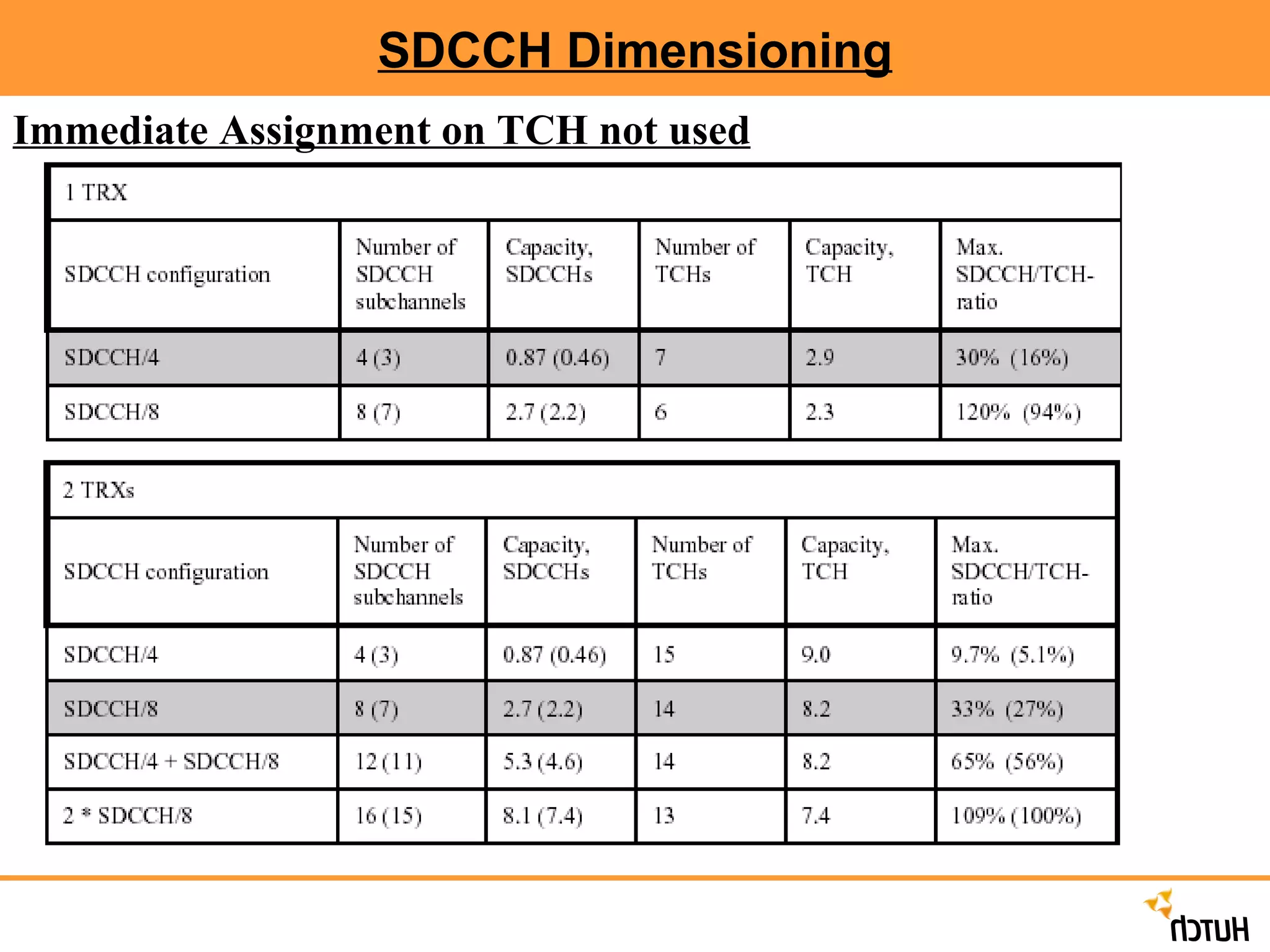
SDCCH Dimensioning ImmediateAssignment on TCH : In case of this feature on the channel administration assigns TCH for signaling instead of an SDCCH, based on 7 different channels allocation strategies (CHAPs) TCH first strategy : Decreases the SDCCH load and enable to use SDCCH/4 in all the cells Traffic load on TCH will in this case increases substantially so this strategy is not recommended. SDCCH first strategy : SDCCH is always allocated first if available, otherwise signaling is performed on TCH.
40.
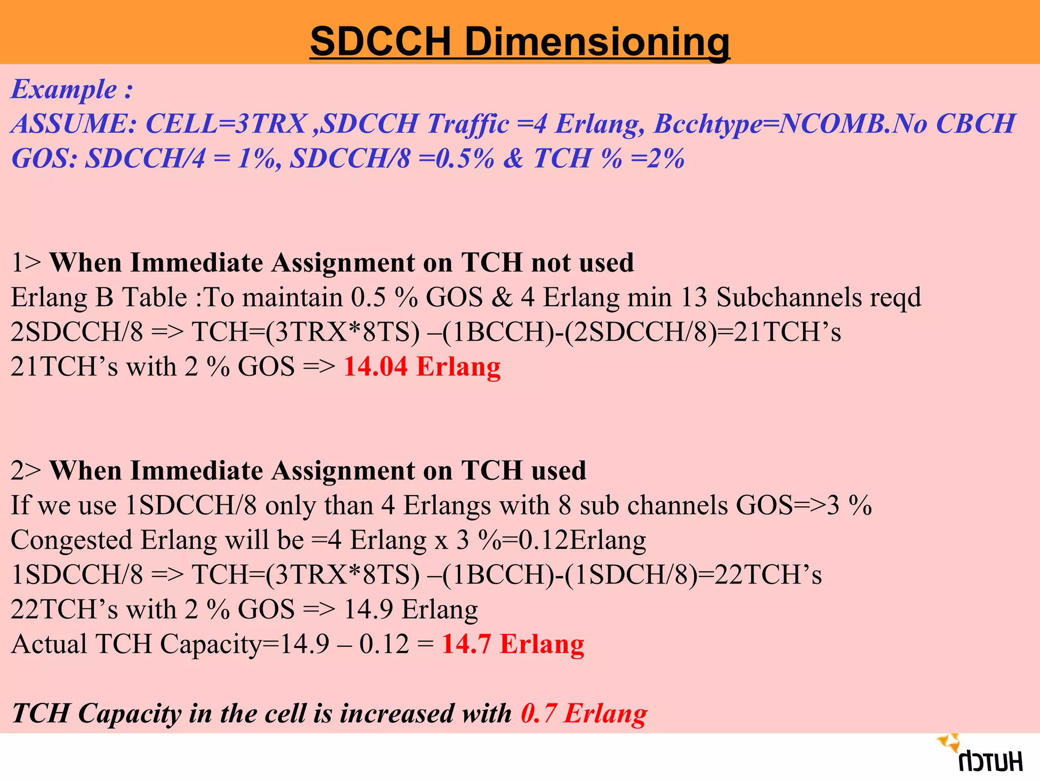
SDCCH Dimensioning Example: ASSUME: CELL=3TRX ,SDCCH Traffic =4 Erlang, Bcchtype=NCOMB.No CBCH GOS: SDCCH/4 = 1%, SDCCH/8 =0.5% & TCH % =2% 1> When Immediate Assignment on TCH not used Erlang B Table :To maintain 0.5 % GOS & 4 Erlang min 13 Subchannels reqd 2SDCCH/8 => TCH=(3TRX*8TS) –(1BCCH)-(2SDCCH/8)=21TCH’s 21TCH’s with 2 % GOS => 14.04 Erlang 2> When Immediate Assignment on TCH used If we use 1SDCCH/8 only than 4 Erlangs with 8 sub channels GOS=>3 % Congested Erlang will be =4 Erlang x 3 %=0.12Erlang 1SDCCH/8 => TCH=(3TRX*8TS) –(1BCCH)-(1SDCH/8)=22TCH’s 22TCH’s with 2 % GOS => 14.9 Erlang Actual TCH Capacity=14.9 – 0.12 = 14.7 Erlang TCH Capacity in the cell is increased with 0.7 Erlang
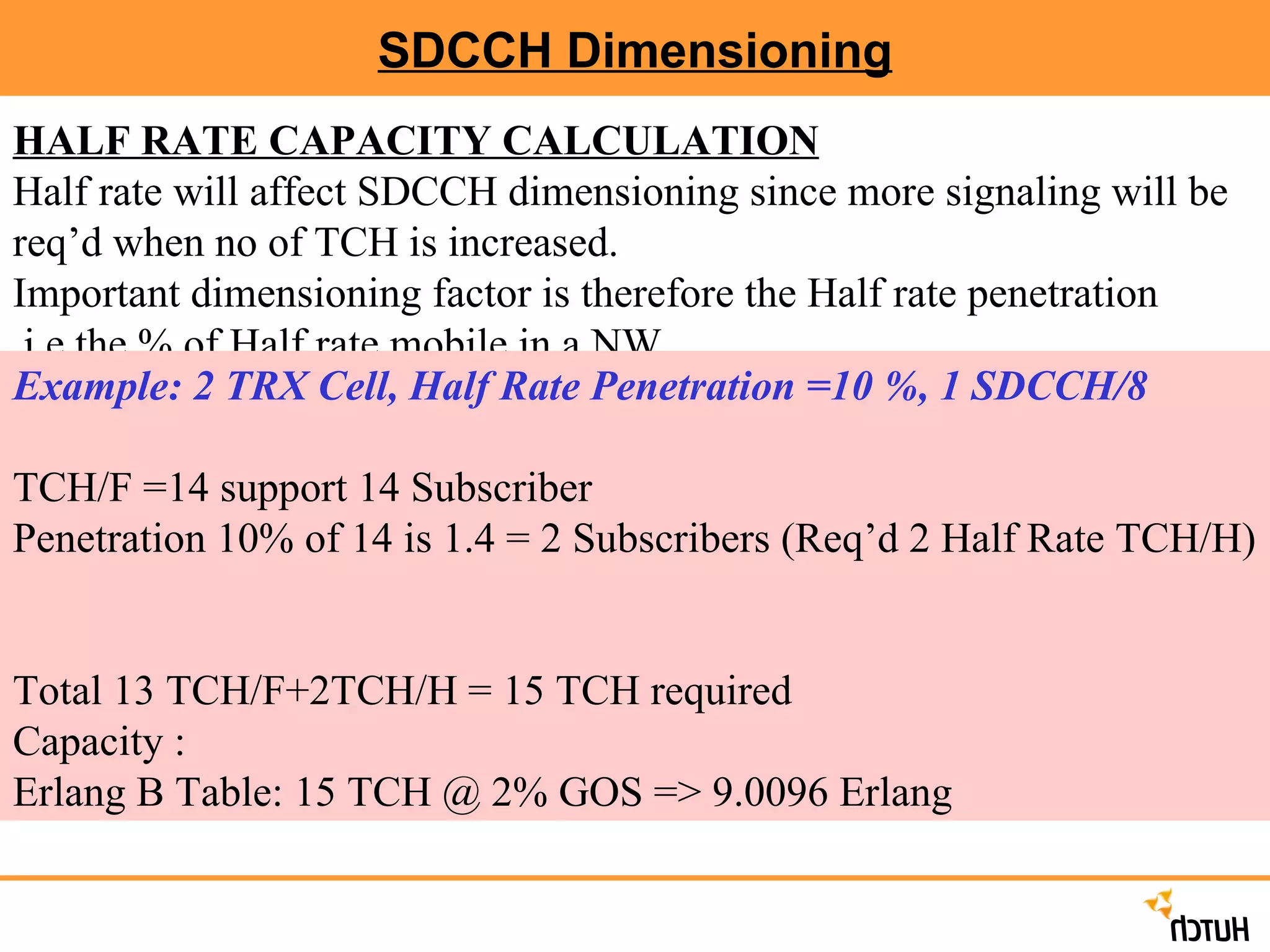
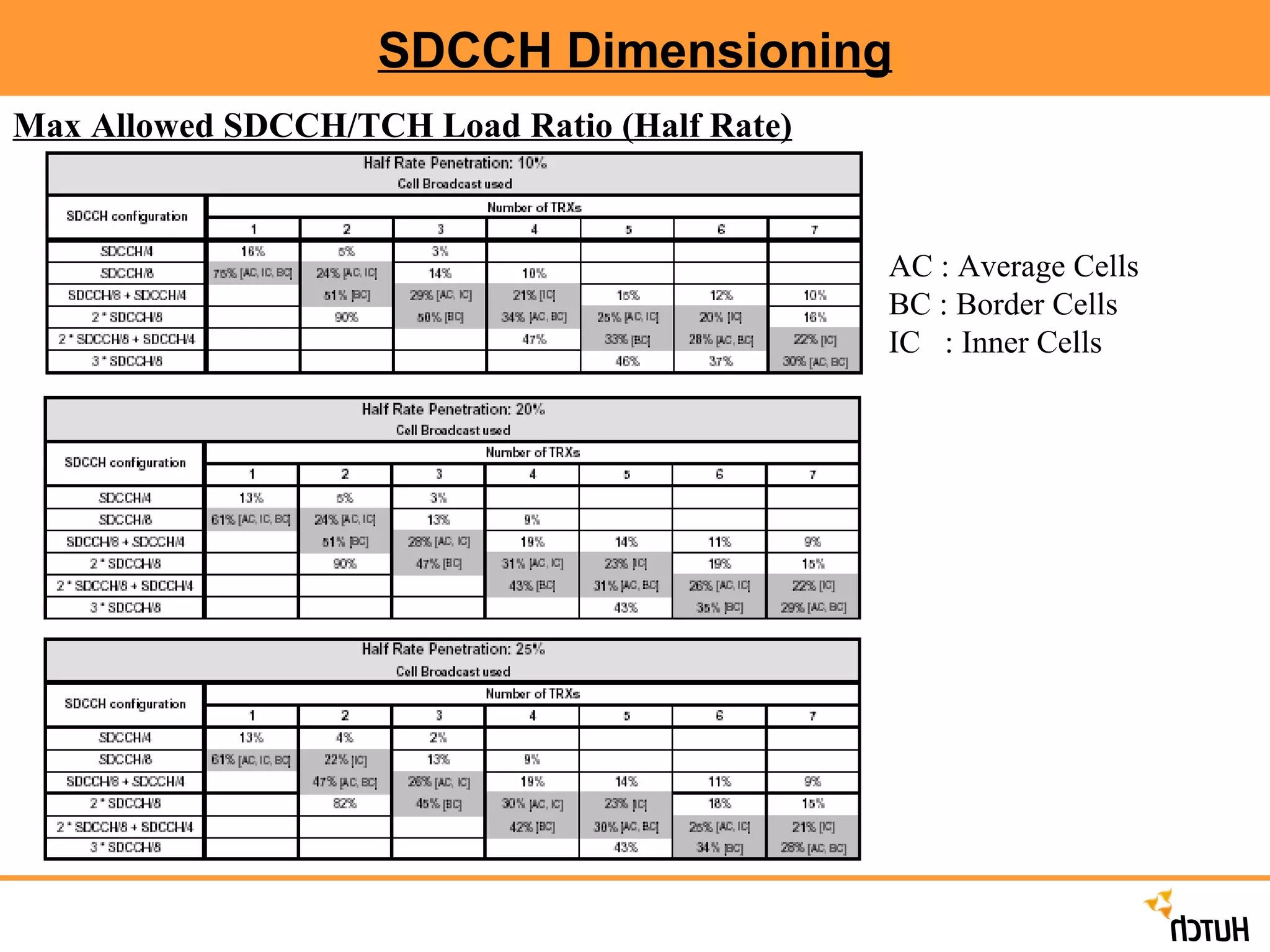
SDCCH Dimensioning HALFRATE CAPACITY CALCULATION Half rate will affect SDCCH dimensioning since more signaling will be req’d when no of TCH is increased. Important dimensioning factor is therefore the Half rate penetration .i.e.the % of Half rate mobile in a NW. Example: 2 TRX Cell, Half Rate Penetration =10 %, 1 SDCCH/8 TCH/F =14 support 14 Subscriber Penetration 10% of 14 is 1.4 = 2 Subscribers (Req’d 2 Half Rate TCH/H) Total 13 TCH/F+2TCH/H = 15 TCH required Capacity : Erlang B Table: 15 TCH @ 2% GOS => 9.0096 Erlang
44.
SDCCH Dimensioning MaxAllowed SDCCH/TCH Load Ratio (Half Rate) AC : Average Cells BC : Border Cells IC : Inner Cells
45.
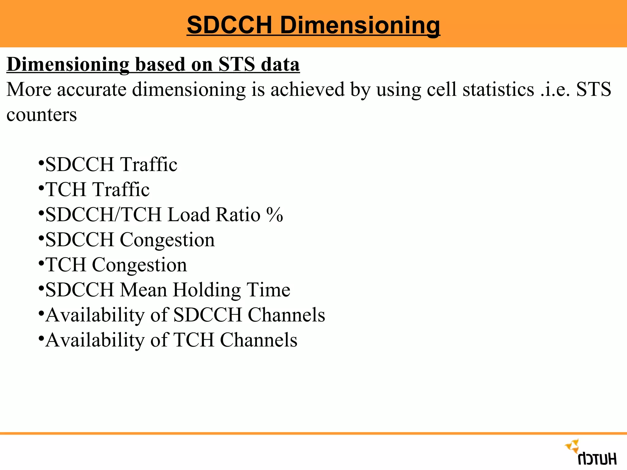
SDCCH Dimensioning Dimensioningbased on STS data More accurate dimensioning is achieved by using cell statistics .i.e. STS counters SDCCH Traffic TCH Traffic SDCCH/TCH Load Ratio % SDCCH Congestion TCH Congestion SDCCH Mean Holding Time Availability of SDCCH Channels Availability of TCH Channels
46.
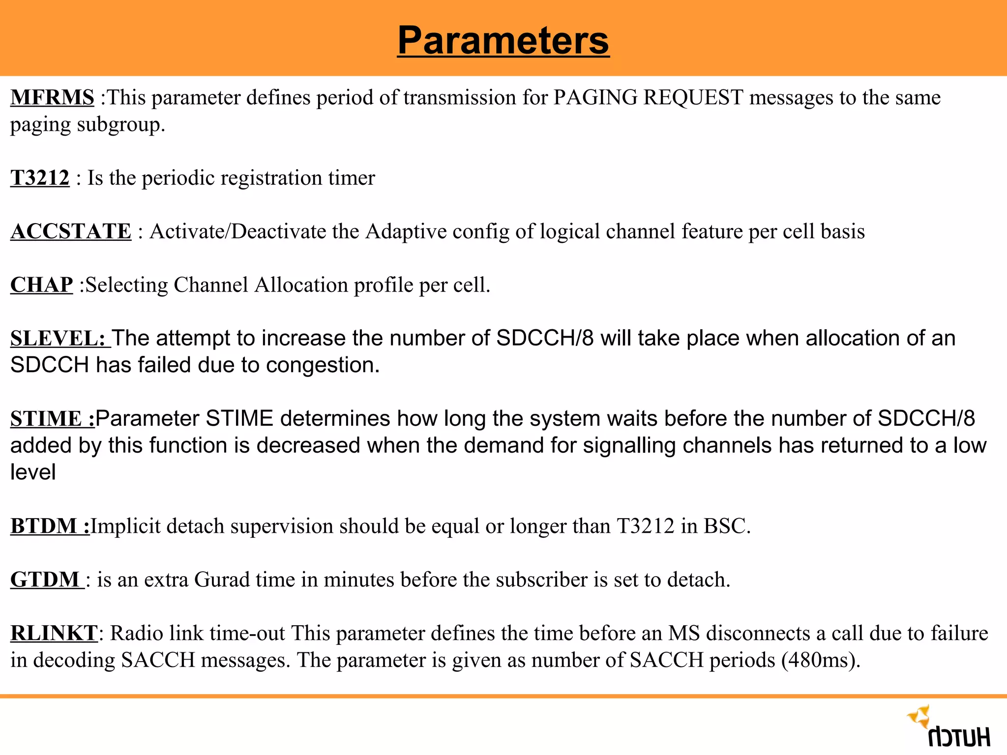
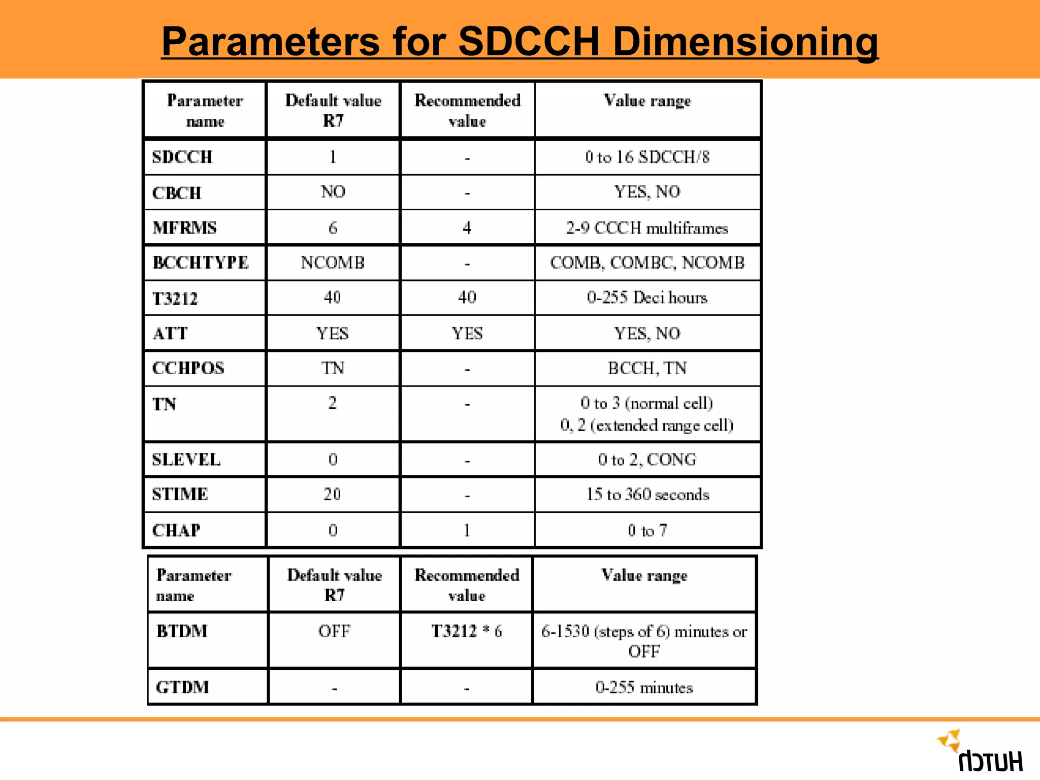
Parameters MFRMS :This parameter defines period of transmission for PAGING REQUEST messages to the same paging subgroup. T3212 : Is the periodic registration timer ACCSTATE : Activate/Deactivate the Adaptive config of logical channel feature per cell basis CHAP :Selecting Channel Allocation profile per cell. SLEVEL: The attempt to increase the number of SDCCH/8 will take place when allocation of an SDCCH has failed due to congestion. STIME : Parameter STIME determines how long the system waits before the number of SDCCH/8 added by this function is decreased when the demand for signalling channels has returned to a low level BTDM : Implicit detach supervision should be equal or longer than T3212 in BSC. GTDM : is an extra Gurad time in minutes before the subscriber is set to detach. RLINKT : Radio link time-out This parameter defines the time before an MS disconnects a call due to failure in decoding SACCH messages. The parameter is given as number of SACCH periods (480ms).
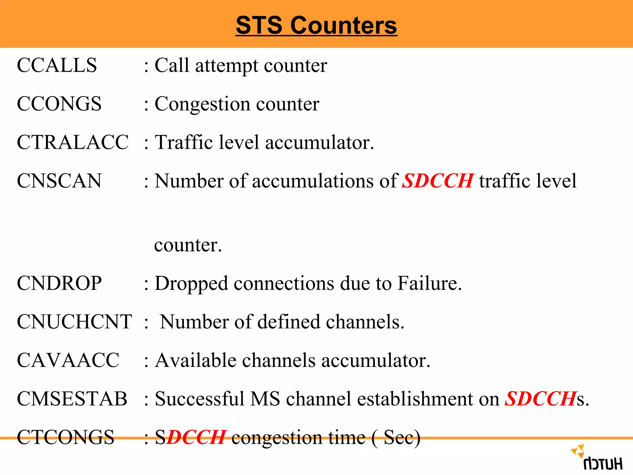
STS Counters CCALLS: Call attempt counter CCONGS : Congestion counter CTRALACC : Traffic level accumulator. CNSCAN : Number of accumulations of SDCCH traffic level counter. CNDROP : Dropped connections due to Failure. CNUCHCNT : Number of defined channels. CAVAACC : Available channels accumulator. CMSESTAB : Successful MS channel establishment on SDCCH s. CTCONGS : S DCCH congestion time ( Sec)
49.
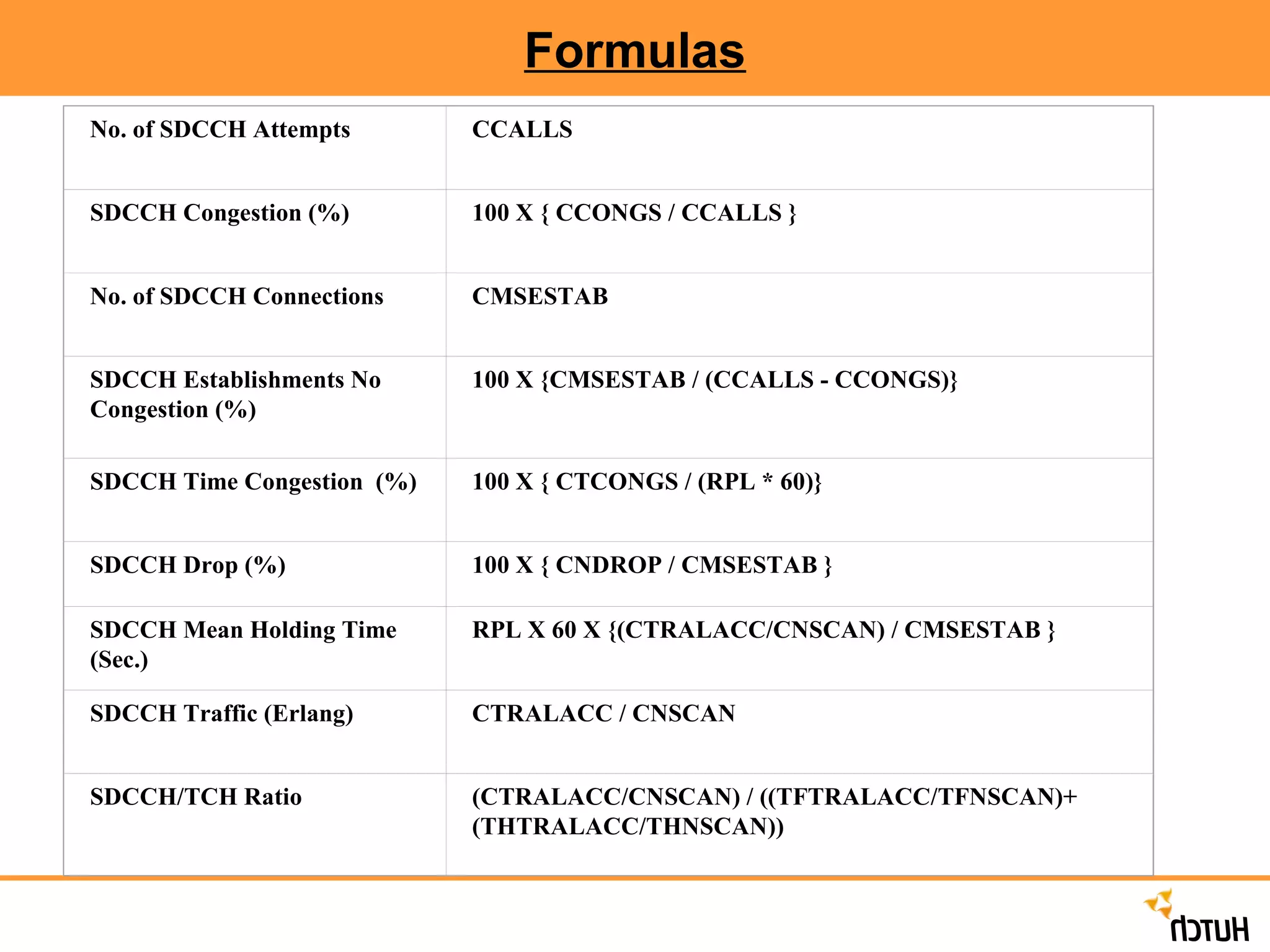
Formulas No. ofSDCCH Attempts CCALLS SDCCH Congestion (%) 100 X { CCONGS / CCALLS } No. of SDCCH Connections CMSESTAB SDCCH Establishments No Congestion (%) 100 X {CMSESTAB / (CCALLS - CCONGS)} SDCCH Time Congestion (%) 100 X { CTCONGS / (RPL * 60)} SDCCH Drop (%) 100 X { CNDROP / CMSESTAB } SDCCH Mean Holding Time (Sec.) RPL X 60 X {(CTRALACC/CNSCAN) / CMSESTAB } SDCCH Traffic (Erlang) CTRALACC / CNSCAN SDCCH/TCH Ratio (CTRALACC/CNSCAN) / ((TFTRALACC/TFNSCAN)+(THTRALACC/THNSCAN))
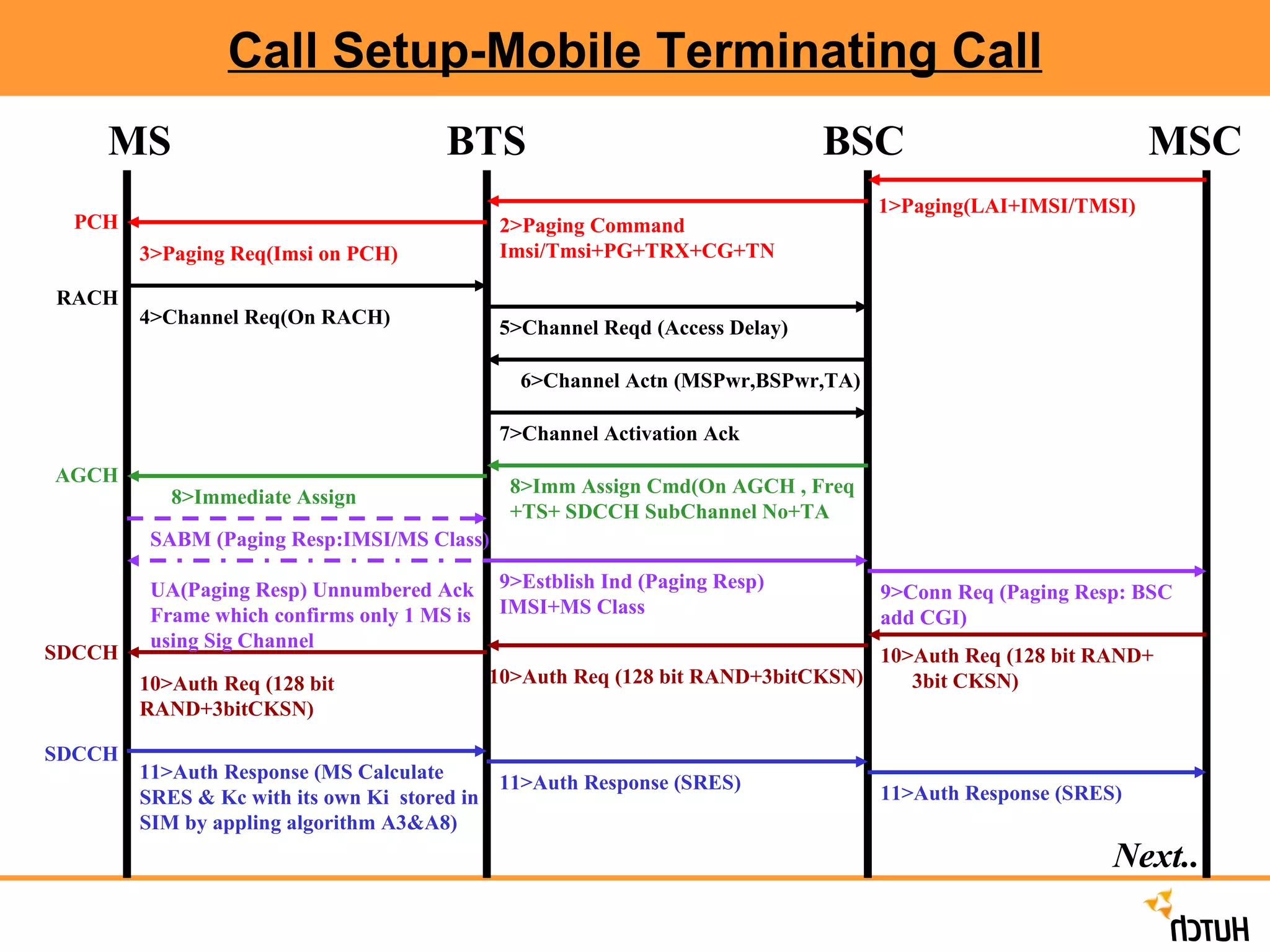
Call Setup-Mobile TerminatingCall 1>Paging(LAI+IMSI/TMSI) 2>Paging Command Imsi/Tmsi+PG+TRX+CG+TN 3>Paging Req(Imsi on PCH) 4>Channel Req(On RACH) 5>Channel Reqd (Access Delay) 6>Channel Actn (MSPwr,BSPwr,TA) 7>Channel Activation Ack 8>Imm Assign Cmd(On AGCH , Freq +TS+ SDCCH SubChannel No+TA 8>Immediate Assign 9>Estblish Ind (Paging Resp) IMSI+MS Class 9>Conn Req (Paging Resp: BSC add CGI) 10>Auth Req (128 bit RAND+ 3bit CKSN) 10>Auth Req (128 bit RAND+3bitCKSN) 10>Auth Req (128 bit RAND+3bitCKSN) 11>Auth Response (MS Calculate SRES & Kc with its own Ki stored in SIM by appling algorithm A3&A8) 11>Auth Response (SRES) 11>Auth Response (SRES) SABM (Paging Resp:IMSI/MS Class) UA(Paging Resp) Unnumbered Ack Frame which confirms only 1 MS is using Sig Channel PCH RACH AGCH SDCCH SDCCH Next.. MS BTS BSC MSC
53.
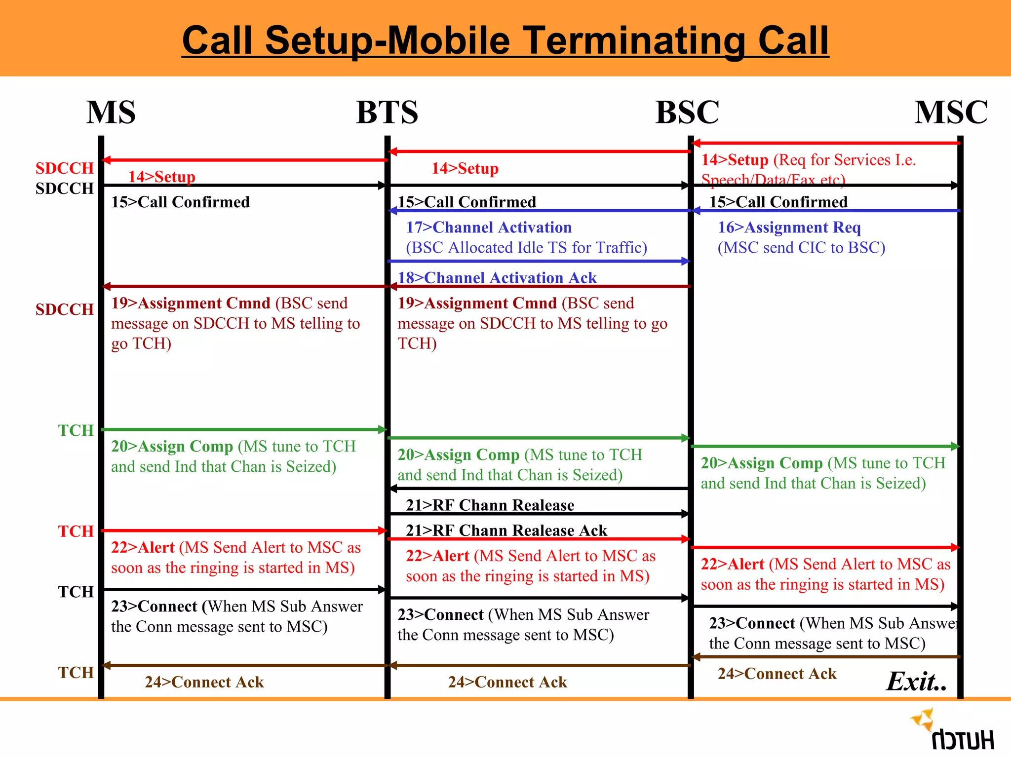
Call Setup-Mobile TerminatingCall 14>Setup (Req for Services I.e. Speech/Data/Fax etc) 15>Call Confirmed 17>Channel Activation (BSC Allocated Idle TS for Traffic) 20>Assign Comp (MS tune to TCH and send Ind that Chan is Seized) 14>Setup 14>Setup 15>Call Confirmed 15>Call Confirmed 16>Assignment Req (MSC send CIC to BSC) 18>Channel Activation Ack 19>Assignment Cmnd (BSC send message on SDCCH to MS telling to go TCH) 19>Assignment Cmnd (BSC send message on SDCCH to MS telling to go TCH) 20>Assign Comp (MS tune to TCH and send Ind that Chan is Seized) 20>Assign Comp (MS tune to TCH and send Ind that Chan is Seized) 21>RF Chann Realease 21>RF Chann Realease Ack 22>Alert (MS Send Alert to MSC as soon as the ringing is started in MS) 22>Alert (MS Send Alert to MSC as soon as the ringing is started in MS) 22>Alert (MS Send Alert to MSC as soon as the ringing is started in MS) 23>Connect ( When MS Sub Answer the Conn message sent to MSC) 23>Connect (When MS Sub Answer the Conn message sent to MSC) 23>Connect (When MS Sub Answer the Conn message sent to MSC) 24>Connect Ack 24>Connect Ack 24>Connect Ack SDCCH SDCCH SDCCH TCH TCH TCH TCH Exit.. MS BTS BSC MSC


![14 gsm bss network kpi (call setup time) optimization manual[1].doc](https://cdn.slidesharecdn.com/ss_thumbnails/14gsmbssnetworkkpicallsetuptimeoptimizationmanual1-140618022447-phpapp02-thumbnail.jpg?width=640&height=640&fit=bounds)