Downloaded 122 times
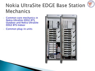
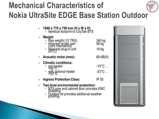
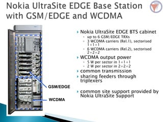
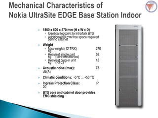
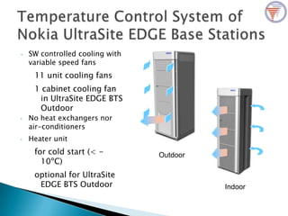
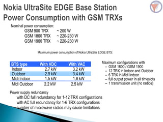
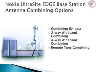
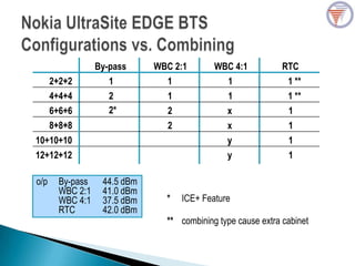
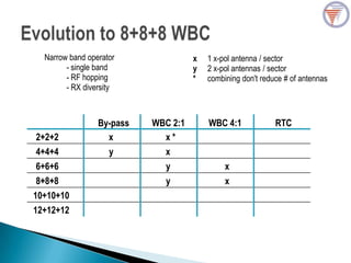
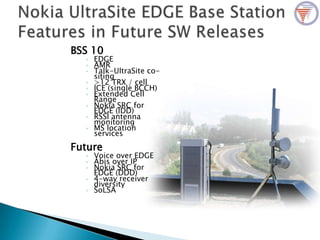

The document provides specifications for Nokia Ultrasite Edge BTS, detailing dimensions, weight, climatic conditions, ingress protection, and power consumption for both indoor and outdoor models. It highlights features such as supported connections, common site support, and various configurations for GSM, WCDMA, and power redundancy options. Additionally, it discusses advanced combining techniques and antennas for improved performance in radio transmission.


