


![QUALCOMM Proprietary QCTest CAIT 3.1 User’s Guide 175
LoggingandMessages
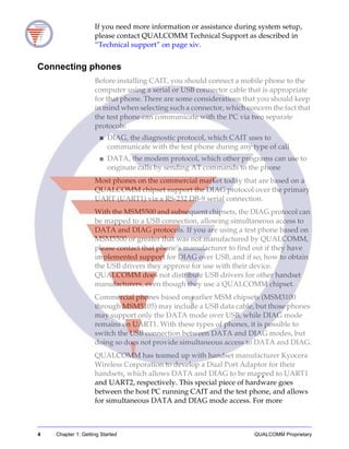
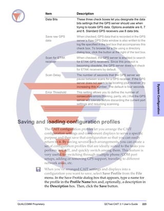
The conversion utility programs are named according to what they
do, as follows:
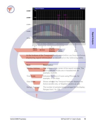
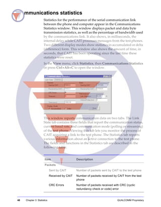
Convert to Non-Dense Log
Use this program, ConvertToNonDenseLog.exe, to convert
Dense-Pack log files into the standard DM format used by
QUALCOMM’s Mobile Diagnostic Monitor and other vendors’
tools. Files already in standard DM format will be unchanged.
Convert to Debug Text
Use this program, ConvertToDebugText.exe, to convert log files to
text files containing only debugging messages and events. This
conversion works with log files in either Dense-Pack or standard
DM format.
Convert to Dense and GPS Text
Use this program, ConvertToDenseAndGPSText.exe, to convert the
log files to text files containing only dense and GPS packet data.
Convert to PPP Dump
Use this program, ConvertToPPPDump.exe, to convert log files to
containing transmit and receive PPP records into PPP Dump format.
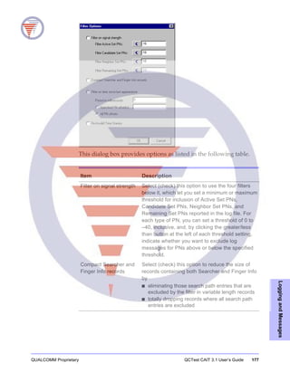
Convert to Thinned Log
Use this program, ConvertToThinnedLog.exe, to reduce the size of
log files by filtering out messages that are redundant or below your
threshold of concern. You can filter out log records by signal
strength or by timestamp.
The log records that you can filter by signal strength are
■ LOG_SRCH2_C
• eng[]
■ LOG_GENRL_TA_C
• path_eng[]
■ LOG_GENRL_TA_SUP_CH_C
• path_eng[]
■ LOG_SRCH_FING_INFO_C
• peaks[]
Threshold values are specified in dB, and the energy records in each
log record are converted to dB before filtering takes place.](https://image.slidesharecdn.com/caitusersguide-130605023737-phpapp02/85/QCTest-CDMA-Air-Interface-Tester-CAIT-3-1-User-s-Guide-189-320.jpg)
![QUALCOMM Proprietary QCTest CAIT 3.1 User’s Guide 179
LoggingandMessages
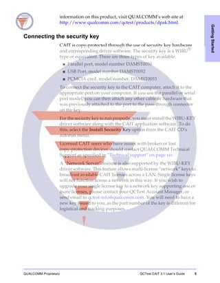
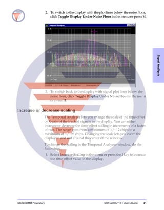
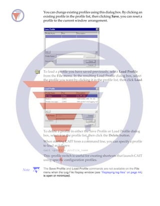
Using a command line
Whenever you invoke these conversion utilities with the addition of
file parameters, instead of displaying the program window, the
utility performs the conversion in the background. The syntax can
be any of the following:
utility_name log_file_name
utility_name [/outfile: output_file_name] log_file_name
utility_name /infile: log_file_name [/outfile: output_file_name]
For example, you can use the following command to convert a log
file to a text file containing only debugging messages:
converttodebugtext m0902094.900
If you don’t supply a name for the output file, the utility will create
one that contains the type of output created, the original filename,
and an appropriate extension. In the above case, the output file will
be named “Debug m0902094900.txt.”
Similarly, the command
converttodenseandgpstext t0902094.300
creates an output file named “Dense and GPS t0902094300.txt”
and
converttonondenselog t0902094.300
creates an output file named “Non-Dense t0902094300.clg.”
Invoking utility_name with no parameters invokes the program
window for the utility.
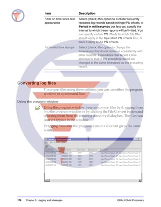
Concatenating log files
The ConcatLog utility lets you combine log files of the same type
into a single file. This program has no Windows interface of its own;
you can either drop a set of files to be concatenated onto the
ConcatLog.exe program (or a shortcut to it), or call it from a
command line followed by the list of files to be concatenated. The
resulting file is named after the input file with the earliest
timestamp, as in “Concatenated input_file.clg”
The ConcatLog utility rejects concatenating log files created with
phones that have different ESNs or model numbers, or that have
overlapping timestamps. However, the utility supports the use of a
/FORCE switch, which lets you override the rejection of log files](https://image.slidesharecdn.com/caitusersguide-130605023737-phpapp02/85/QCTest-CDMA-Air-Interface-Tester-CAIT-3-1-User-s-Guide-193-320.jpg)


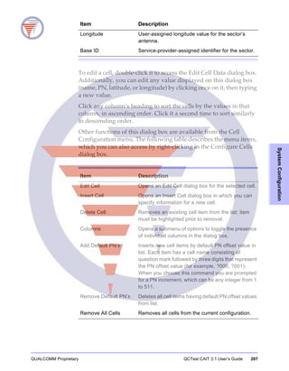

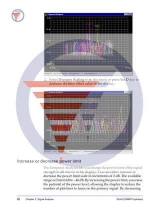
![228 Chapter 9: User-defined Forms QUALCOMM Proprietary
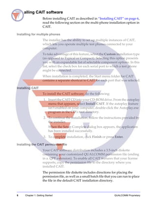
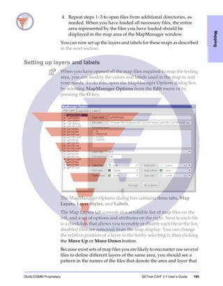
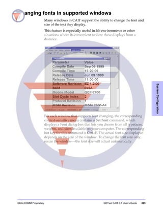
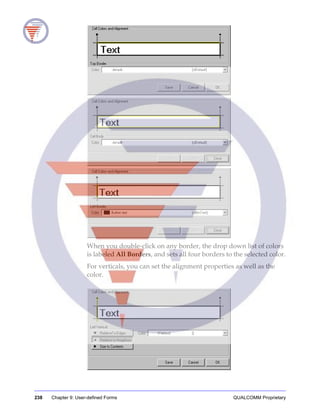
When you have set up the new form as desired on this dialog box,
click OK. The new form appears.
When you are editing a form, a context-sensitive menu, is available
on the CAIT main menu. The menu is named Editing: form_name,
or Editing:[New Form] if the form has not been named. This Editing
menu contains the same editing menu options that can be accessed
by right-clicking on the form.
Saving a form
Because of the number of steps involved in creating a working form,
it is recommended that you regularly save your changes to the form.
Doing so provides an earlier version of the form that you can revert
to if any of your changes are accidentally deleted or yield undesired
results.
To save a form, select File, then Save from the Editing menu.
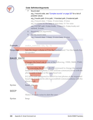
To save a copy of an existing form to a new file, choose File, then
Save As from the Editing menu. A dialog box appears.
In this dialog box, type a name for the form in the Form Name box,
then click Save.](https://image.slidesharecdn.com/caitusersguide-130605023737-phpapp02/85/QCTest-CDMA-Air-Interface-Tester-CAIT-3-1-User-s-Guide-242-320.jpg)


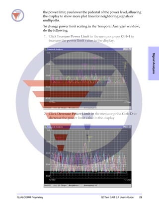
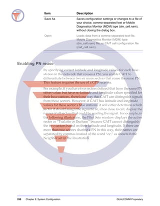
![248 Appendix A: Script Command List QUALCOMM Proprietary
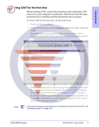
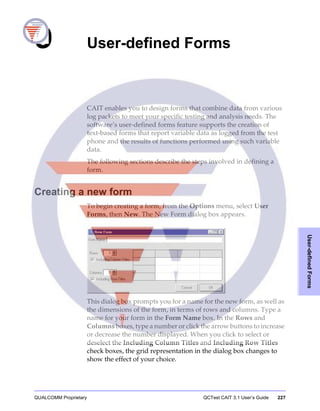
APPEND_LOG
Opens a script log in append mode so the new data is added to the
file rather than a new file created.
Syntax append_log filename.ext
Example append_log mylogfile.txt
Response New messages are added to the file without overwriting the existing
content.
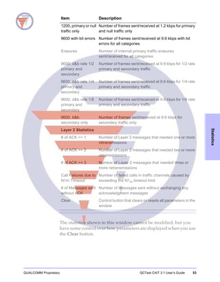
ANNOTATE
Adds an annotation to the current log file, if logging is enabled.
Syntax annotate “annotation_string”
APR_LIST_WR
Writes an abbreviated Preferred Roaming List (PRL) to a QCP-1900®
or QCT®-1200 phone using a shortcut write command. This allows
specifying only channel numbers for the PRL list. All other entries
default to wild cards.
Syntax apr_lst_wr {nam, ch1, ch2...ch32}
Example apr_lst_wr {0, 500, 250}
Response The list containing the channel numbers is sent to the mobile phone.
APR_LIST_WR_683
Loads a standard-format abbreviated IS-683-A preferred roaming
list.
Syntax apr_list_wr_683 {nam, [cell], [pcs], channel_1, [channel_2,
channel_3,...] [AMPS_A | AMPS_B]}
The “cell” argument specifies cellular channels; “pcs” specifies PCS
channels. Up to 32 channels can be specified per NAM.
Example apr_list_wr_683 {0, cell, 777, pcs, 500, AMPS_B}
Response Writes a PRL instructing NAM 1 to look for CDMA cellular service
on channel 777, CDMA PCS service on channel 500, or B-side AMPS
service.](https://image.slidesharecdn.com/caitusersguide-130605023737-phpapp02/85/QCTest-CDMA-Air-Interface-Tester-CAIT-3-1-User-s-Guide-262-320.jpg)
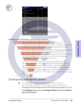
![QUALCOMM Proprietary QCTest CAIT 3.1 User’s Guide 249
ScriptCommandList
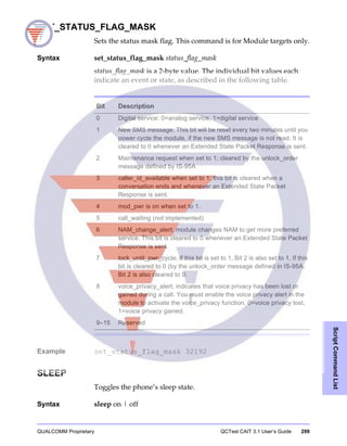
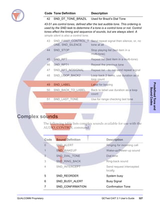
AUDIO_CONTROL
Allows control of various audio characteristics of the module. This
command is for Module targets only.
Syntax audio_control {audio_command_code, [arg_1,...arg_8]}
The following table lists the possible values for audio_command_code
and the arguments required or available for each code.
Code Definition/Arguments
0 Set audio path and muting
arg_1=audio path: 0=no path, 1=handset path, 2=external path
arg_2=mute output path: 0=no, 1=yes
arg_3=mute input path: 0=no, 1=yes
1 Set voice volume
arg_1=volume level for handset: 0–7
arg_2=volume level for hands-free kit (HFK) speaker: 0–7
2 Set ringer volume
arg_1=volume level for handset: 0–7
arg_2=volume level for hands-free kit (HFK) speaker: 0–7
3 DTMF start
arg_1=tone definition, see “Predefined tones” on page 325 for a list of
possible values
4 DTMF stop (no arguments)
5 Tone start
arg_1=tone definition, see “Predefined tones” on page 325 for a list of
possible values
arg_2=duration (in milliseconds)
arg_3=audio path: 0=no path, 1=handset path, 2=external path
arg_4=sound class: 1=beep, 2=voice beep, 3=voice
arg_5=volume for handset: 0–3 for beep or voice beep, 0–7 for voice
arg_6=volume level for hands-free kit (HFK) speaker: 0–7 for beep or
voice beep, 0–3 for voice
arg_7=DTMF path: 0=play locally, 1=transmit, 2=play locally and
transmit, 3=mute
6 Tone stop (no arguments)](https://image.slidesharecdn.com/caitusersguide-130605023737-phpapp02/85/QCTest-CDMA-Air-Interface-Tester-CAIT-3-1-User-s-Guide-263-320.jpg)
![252 Appendix A: Script Command List QUALCOMM Proprietary
CLOSE_CAIT_SCREEN
Closes a named CAIT display window. To view a list of valid
window names, use the LIST_CAIT_SCREENS command described
on page 275.
Syntax close_cait_screen “screen_name”
CLOSELOG
Closes the currently open transcript file. If no transcript file is open,
a message informing the user of that fact is displayed.
Syntax closelog
See also openlog
append_log
CLS
Clears the CAIT display screen.
Syntax cls
COMP (analog test command)
Turns the compander (compressor/ expander) on or off.
Syntax comp on | off
Example comp on
Response Turns the compander on.
COMPUTE_RTC_LONG_CODE_MASK
Computes the Reverse Traffic Channel long code mask by reading
the TRANSMIT_ATI value from either the
HDRAMP_ADDRESS_DATA NV item or the command line.
Syntax compute_rtc_long_code_mask [transmit_ATI]
transmit_ATI is an optional parameter for specifying the access
terminal identifier of the transmitting handset.](https://image.slidesharecdn.com/caitusersguide-130605023737-phpapp02/85/QCTest-CDMA-Air-Interface-Tester-CAIT-3-1-User-s-Guide-266-320.jpg)
![256 Appendix A: Script Command List QUALCOMM Proprietary
DIPSW
Sets the specified DIP switches to on (1) or off (0), where the value is
16 bit hexadecimal. Use the Dip Switches dialog box described in
“DIP switch configuration” on page 132 to determine the
appropriate hexadecimal value for the DIP switch settings you
desire.
Syntax dipsw [value]
Example dipsw 0xFFFF
Response This turns on all of the DIP switches.
DP_READ
Creates a dialing plan file for WLL phones by reading from the
specified NAM.
Syntax dp_read nam file_string
Example dp_read 1 dialplan.bin
Response The dialing plan for NAM 2 is written to a file named dialplan.bin.
DP_WRITE
For WLL phones, loads a dialing plan, created by a dialing plan tool,
to the specified NAM.
Syntax dp_write nam file_string
Example dp_write 1 dialplan.bin
Response The dialing plan in a file named dialplan.bin is written to NAM 2.
DTMF (analog test command)
Activates the DTMF generator with a digit, where digit is 1–9, 0,*,#,
or off.
Syntax dtmf [digit]
Example dtmf 0](https://image.slidesharecdn.com/caitusersguide-130605023737-phpapp02/85/QCTest-CDMA-Air-Interface-Tester-CAIT-3-1-User-s-Guide-270-320.jpg)
![QUALCOMM Proprietary QCTest CAIT 3.1 User’s Guide 257
ScriptCommandList
END_WCDMA_CALL
Terminates a WCDMA call.
Syntax end_wcdma_call
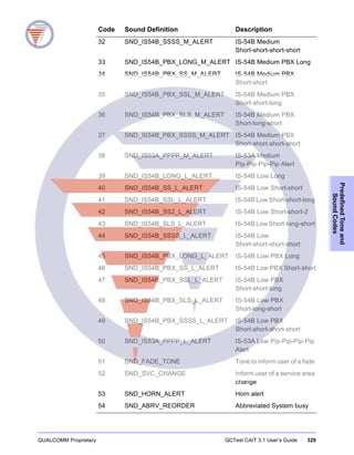
ERR_CLR
Clears one or all of the errors in the NV memory. If item is 0xFF, it
clears all errors, otherwise it clears that one entry.
Syntax err_clr [item]
Example err_clr 0xFF
Response All errors in non-volatile (NV) memory are cleared.
Note The only time this command might be used is at the beginning of a test run. It is
suggested that at the end of the test run, the ERR_GET command may be used
to retrieve any errors that occurred during the test run.
ERR_GET
Reads all the errors in the NV memory and displays them.
Syntax err_get
Example err_get
Response The total logged messages: 0002
The total ignored messages: 0041
Note The meaning of the errors logged in NV memory is QUALCOMM proprietary. If
errors are found, they can be recorded and sent to QUALCOMM Technical
Support for evaluation.
EXIT_CAIT
This command causes CAIT to exit. It is intended for use by COM
automation clients to force CAIT to exit when done. If a COM
applications or script does not execute this command, then CAIT
will continue to run, allowing further COM applications or scripts to
Storage addr The err Filecode Line #
0 7A mc 1442 NF
1 FF rxc 3001 NF](https://image.slidesharecdn.com/caitusersguide-130605023737-phpapp02/85/QCTest-CDMA-Air-Interface-Tester-CAIT-3-1-User-s-Guide-271-320.jpg)


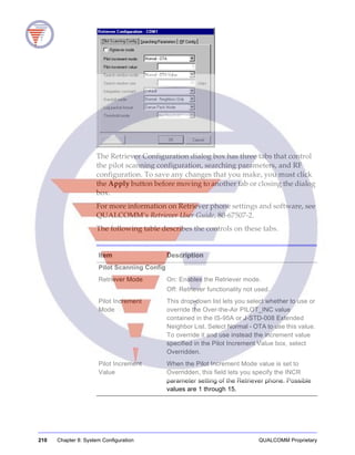
![QUALCOMM Proprietary QCTest CAIT 3.1 User’s Guide 269
ScriptCommandList
Control document (ICD) which is available to QUALCOMM
subscriber and test equipment licensees. (This document requires a
license and agreement beyond that which is required for CAIT.) The
subcommand parameter provides a value for the GPS_CONTROL
parameter to this DIAG command. If a single numeric value is
provided, it is interpreted as a single-byte data value for the
command, while a hex string can be used to pass more information
to DMSS. The hex string is provided in the same manner as in the
SEND_DATA command (see “SEND_DATA” on page 291). The len
parameter is ignored.
Syntax gps_sess_ctrl subcommand len data_byte
gps_sess_ctrl subcommand “hex_string”
HELP
Displays a brief description of the command syntax. If entered with
no argument, all commands are listed with help text. If the topic
option is used, an explanation of only that topic is displayed.
Syntax help [topic]
Example 1 help
Response All commands with topic options are displayed.
Example 2 help NV
Response A complete list of NV items are displayed by name. For more
specific help with NV items, type help nv_read or help nv_write in
the Scripting window.
HDR_DIPSW_CLEAR_ALL
Clears all HDR DIP switches.
Syntax hdr_dipsw_clear_all
HDR_DIPSW_RD_MASK
Reads and displays the HDR DIP switch mask.
Syntax hdr_dipsw_rd_mask](https://image.slidesharecdn.com/caitusersguide-130605023737-phpapp02/85/QCTest-CDMA-Air-Interface-Tester-CAIT-3-1-User-s-Guide-283-320.jpg)
![QUALCOMM Proprietary QCTest CAIT 3.1 User’s Guide 271
ScriptCommandList
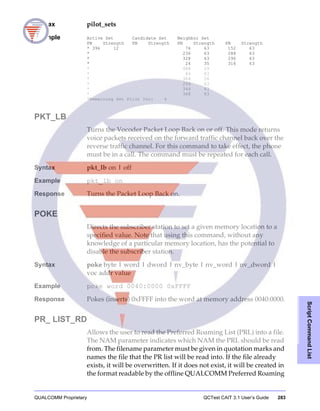
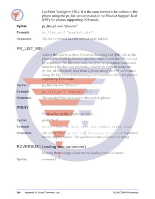
Syntax pr_list_wr nam “filename”
Example pr_list_wr 0 “nam1prl.hin”
Response The list in the file nam1prl.hin is sent to the mobile phone.
See also pr_list_wr
HS_LOCK
Locks or unlocks manual key operation for handset emulation. It is
recommended that if the handset emulation commands are used
(key, get_screen), the manual operation be locked out for
consistency.
Syntax hs_lock l | u
Example hs_lock l
Response Normal manual keypad operation is locked out.
See also key
get_screen
INP
Requests a port input operation where port is accessed either as a
byte (8 bits) or word (16 bits) port, depending on the syntax of the
command.
Syntax inp byte | word
Example inp byte 0x01
Response Requested byte is input from port address 0x01.
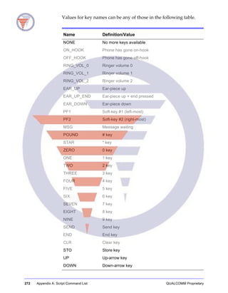
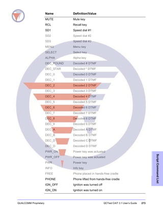
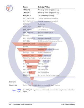
KEY
Sends a specified key press to the phone. The keys include keys
other than just handset keys.
Syntax key [key_name]](https://image.slidesharecdn.com/caitusersguide-130605023737-phpapp02/85/QCTest-CDMA-Air-Interface-Tester-CAIT-3-1-User-s-Guide-285-320.jpg)
![276 Appendix A: Script Command List QUALCOMM Proprietary
LOG_ON_DEMAND
Requests that the DMSS immediately output a log packet matching
the log code specified. The log packet is to be delivered via the nor-
mal logging mechanism of the phone.
Syntax log_on_demand log_code
LOGGING
Turns data logging on and off from the scripting screen command
line or in a script file. This command is equivalent to typing Alt+L
from anywhere in CAIT. If using this command to turn logging on,
you can optionally specify a file name to which the log will be
written.
Syntax logging on [“filename”]| off
Example logging on
Response CAIT starts polling the test phone for logging messages.
LOGMASK
Used to change the current log mask from the scripting screen or in
a script file. If logging is on when this command is executed, the new
log mask is sent to the phone. If not, the log mask is set in CAIT. Use
the check boxes described in “Logging Mask dialog box” on page
160 to determine the appropriate hexadecimal mask value for the log
mask configuration you desire.
This command is provided in two formats with distinctly different
syntaxes.
Syntax 1 logmask [equipment_ID] “mask_value_string”
Where equipment_ID is an optional integer value that specifies a
DMSS equipment ID and mask_value_string is the new log mask,
which is specified as a string, in quotes. The string format lets you
copy log mask values from the Logging Mask dialog box (see
“Logging Mask dialog box” on page 160) and paste them into your
scripts. If you omit the equipment_ID specification, the default value
of 1 is used, signifying the CDMA logging mask.
Example 1 logmask 4 “FFFFFFFF”
Response This turns on the first 32 log codes in the WCDMA logging mask.](https://image.slidesharecdn.com/caitusersguide-130605023737-phpapp02/85/QCTest-CDMA-Air-Interface-Tester-CAIT-3-1-User-s-Guide-290-320.jpg)
![278 Appendix A: Script Command List QUALCOMM Proprietary
Example 2 mode reset
Response Directs the subscriber station to perform a software restart, and the
test phone will cycle power. This command is not valid unless the
phone is already in an offline state first.
NV_READ
Requests an NV (non-volatile memory) item by name or numeric ID
from the phone. There are hundreds of NV items. For a complete
listing of the NV items which can be read, type help nv_read. Some
of the items need modifiers to specify which element you want to
read.
Syntax nv_read item|item_number [modifiers]
Example nv_read esn
Response The test phone ESN (electronic serial number of test phone) is
requested.
NV_READ_HEX
Requests an NV (non-volatile memory) item by name or numeric ID
from the phone, in hexadecimal format. There are hundreds of NV
items. For a complete listing of the NV items which can be read, type
help nv_read_hex. Some of the items need modifiers to specify
which element you want to read.
Syntax nv_read_hex item|item_number [modifiers]
NV_WRITE
Provides a value to be written to the named NV item.
Syntax nv_write item|item_number {parameters}
Example nv_write slot_cycle_index{1}
Response The value 1 is written to the slot cycle index NV item. Note that
because different NV items require different types of data, the
argument list varies from item to item. Type help nv_write for an
argument list. The dot operator ( ) is required, but the content can be
a string, address, or numeric. The list may have up to 40 arguments.
A comma must separate each item.](https://image.slidesharecdn.com/caitusersguide-130605023737-phpapp02/85/QCTest-CDMA-Air-Interface-Tester-CAIT-3-1-User-s-Guide-292-320.jpg)
![QUALCOMM Proprietary QCTest CAIT 3.1 User’s Guide 279
ScriptCommandList
NV_WRITE_ITEM
This command allows you to write an NV item by specifying the
numeric ID assigned to it.
Syntax nv_write_item item_number {parameters}
item_number specifies the NV item to write.
parameters is a list of byte values to be written, separated by spaces
or commas.
NV_WRITE_ONLINE
Writes an NV item as does nv_write, but does so without going
offline.
Syntax nv_write_online item {parameters}
Example nv_write_online ringer_level {2}
Response The value 2 is written to the ringer level NV item while the phone
remains online.
See Also nv_write
OPEN_CAIT_SCREEN
Opens a named CAIT display window. To view a list of valid
window names, use the LIST_CAIT_SCREENS command described
on page 275.
Syntax open_cait_screen “screen_name”
OPENLOG
Open a transcript file and writes every line echoed to the screen in
the script scrolling area. An optional ECHO switch enables
recording of scripting commands within the log file opened. See the
command “CLOSE_CAIT_SCREEN” on page 252 to close the file.
Syntax openlog “log_file_name” [echo]
Example openlog “foo.dat” echo
Response The file foo.dat is opened for transcript output. The quotation marks
are not required but are recommended for correct interpretation. For](https://image.slidesharecdn.com/caitusersguide-130605023737-phpapp02/85/QCTest-CDMA-Air-Interface-Tester-CAIT-3-1-User-s-Guide-293-320.jpg)
![QUALCOMM Proprietary QCTest CAIT 3.1 User’s Guide 281
ScriptCommandList
PARM_SET
Sets the specified parameters. A -1 value clears all parameters. Refer
to Appendix E of the IS-95-A or J-STD-008, Table E-1, CDMA
Retrievable and Settable Parameters, for the parameter identification
values.
Syntax parm_set parm_id [value]
Example parm_set -1 0
Response All parameters are cleared (reset to zero).
PASSWORD
Allows the user to send the phone’s security password. This is the
password associated with the DMSS Security Plan, not to be
confused with the Service Programming Code. If a phone has this
password set, sending this command with the correct password will
unlock secure features (memory peek/poke, port I/O). If the wrong
password is sent, the phone powers off. The password argument is
a 16-character string of hexadecimal digits (0–9, A–F), representing
the 8-byte password of the phone.
Syntax password “password”
Example password “0123456789abcdef”
Response The security password of 0x0123456789abcdef is sent to the
phone to unlock the secure features of the phone.
PAUSE
Stops reading commands from the script file until a keystroke is
entered.
Syntax pause
Example pause
Response A dialog box with the text “Paused ! Press Enter or click
the OK Button” opens. The execution of the script is suspended
till the user closes this dialog box.](https://image.slidesharecdn.com/caitusersguide-130605023737-phpapp02/85/QCTest-CDMA-Air-Interface-Tester-CAIT-3-1-User-s-Guide-295-320.jpg)
![QUALCOMM Proprietary QCTest CAIT 3.1 User’s Guide 285
ScriptCommandList
RCVS1 (analog test command)
Returns the message count on the analog control channel. Shorthand
for rcversus1.
Syntax rcvs1
RSSI (analog test command)
Returns the current analog RSSI measurement. This command is for
Module targets only.
Syntax RSSI
RUN
Starts executing commands from a script file. This also allows one
script file to execute another.
Syntax run [script_file_name]
Example run test0001.scr
Response CAIT starts running the test0001.scr script file. This command is
entered on the command line or contained in a script file. When
entered on the command line, the file is opened and commands are
parsed and executed from the beginning of the file to the end. When
this command is contained in a script file, the position in the current
file is remembered, the new file is run, then processing is resumed in
the original file. Nesting of files up to five deep is supported.
RXMUTE (analog test command)
Mutes or unmutes the receiver audio signal.
Syntax rxmute on | off
Example rxmute off
Response Unmutes the receiver audio signal.
SATOFF (analog test command)
Disables the SAT (supervisory audio tone) transmission.
Syntax satoff](https://image.slidesharecdn.com/caitusersguide-130605023737-phpapp02/85/QCTest-CDMA-Air-Interface-Tester-CAIT-3-1-User-s-Guide-299-320.jpg)
![286 Appendix A: Script Command List QUALCOMM Proprietary
SATON (analog test command)
Transmits a SAT (supervisory audio tone). Value may be 5970, 6000,
or 6030 Hz.
Syntax saton [value]
Example saton 6000
Response Transmits a SAT at 6000 Hz.
SAVE_CAIT_SCREEN
Saves the entire application screen in a bitmap (.BMP) file (just like
selecting CAIT Screen from the CAIT Capture menu does). You can
optionally include a quoted string to specify the file name to use. The
bitmap files are saved in the folder where the CAIT program resides.
If you specify the name of a file that already exists, the new file will
overwrite the older one. If you do not specify a file name, a default
name will be used, in the format CAIT_SCREENx.bmp, where x is
an integer, beginning with 1, which is incremented for each file you
save.
Note This scripting command has one significant limitation: the only portion of the
application window that can be captured is whatever portion is currently visible
on the display. If the main window of CAIT is partially off-screen, or is blocked
by another application’s window, the hidden portion will not be captured.
Syntax save_cait_screen ["file_name"]
Example save_cait_screen "screen1.bmp"
Response Saves the current phone screen to a bitmap file named screen1.bmp.
SAVE_PHONE_SCREEN
This command saves an image of the current phone screen to a
bitmap (.BMP) file, which is specified as a quoted string. The bitmap
files are save in the folder where the CAIT program resides. If you
specify the name of a file that already exists, the new file will
overwrite the older one.
Syntax save_phone_screen "file_name"
Example save_phone_screen "screen1.bmp"
Response Saves the current phone screen to a bitmap file named screen1.bmp.](https://image.slidesharecdn.com/caitusersguide-130605023737-phpapp02/85/QCTest-CDMA-Air-Interface-Tester-CAIT-3-1-User-s-Guide-300-320.jpg)

![292 Appendix A: Script Command List QUALCOMM Proprietary
SEND_IS801_MESSAGE
The send_is801_message command can be used to send IS-801
messages to the phone.
The gpsOne window, described in “gpsOne information” on page
142, displays the gpsOne commands. Refer to the QCTest Serial Data
Interface Control Document, 80-B1188-1 for diag message
descriptions. Refer to the gpsOne Position Determination Messaging
and Parameters document, 80-V0726-1, for a description of the IS-801
message fields.
Syntax send_is801_message gps_control file_name [set_bit_option]
gps_control defines messages for acquisition assistance, sensitivity
assistance, and position location response.
file_name is the name of a file containing text data in the struct
iteration language toolkit (SILK) input format, describing the IS-801
message fields.
Caution The templates have values that work with SILK. Providing incorrect values may
cause CAIT to hang while the SILK functions wait for additional data.
Include the optional set_bit_option parameter to give the mobile
additional information.
Examples The values for the gps_control, file_name, and set_bit_option
parameters must be grouped as shown.
IS-801 Acquisition assistance message:
send_is801_message 1 silkspecAA.txt UseMessageTime
IS-801 Sensitivity assistance message:
send_is801_message 2 silkspecSA.txt WipeOff
IS-801 Provide position location response message:
send_is801_message 5 silkspecPL.txt (Reserved)
IS-801 Provide Almanac data message:
send_is801_message 8 silkspecAlmanac.txt (Reserved)
IS-801 Provide Ephemeris data message:
send_is801_message 9 silkspecEphemeris.txt
(Reserved)](https://image.slidesharecdn.com/caitusersguide-130605023737-phpapp02/85/QCTest-CDMA-Air-Interface-Tester-CAIT-3-1-User-s-Guide-306-320.jpg)
![QUALCOMM Proprietary QCTest CAIT 3.1 User’s Guide 293
ScriptCommandList
SEQ_NUMS
Requests that packets be sent with sequence numbers included.
Syntax seq_nums
SER_REPORT
Reports the Symbol Error Rate (SER) counts.
Syntax ser_report
Example ser_report
Response Polls the subscriber station for current SER statistics, without
resetting the counters.
SER_RESET
Resets the Symbol Error Rate (SER) statistics.
Syntax ser_reset
Example ser_reset
Response Resets the SER counters.
SET_ALARMS_DIR
Set the name of the directory containing alarm definition files.
Syntax set_alarms_dir directory
SET_ATTN (analog test command)
Sets the analog power control to a specific value (range 0−7).
Syntax set_attn [value]
Example set_attn 1
Response Power control is set to 1 volt.](https://image.slidesharecdn.com/caitusersguide-130605023737-phpapp02/85/QCTest-CDMA-Air-Interface-Tester-CAIT-3-1-User-s-Guide-307-320.jpg)

![QUALCOMM Proprietary QCTest CAIT 3.1 User’s Guide 297
ScriptCommandList
SET_LOG_DIR
Sets the directory where log files are written, either permanently or
temporarily.
Syntax set_log_dir “logging_directory_path” [TEMPORARY]
Example set_log_dir “c:cait_logjust4now” TEMPORARY
Response Sets the logging directory to the specified directory until the script
finishes running.
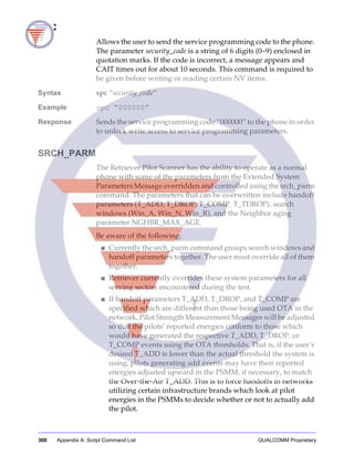
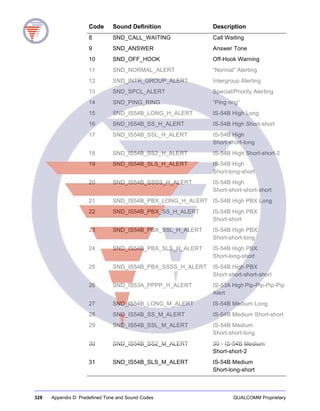
SET_MAX_FWD_MUX
Sets the maximum number of supplemental channels. This
command is for MDR targets only.
Syntax set_max_fwd_mux service_option max_num_sup_ch
service_option is a code representing the type of transmission for
which you are setting a maximum number of supplemental
channels, as described in the following table.
Code Description
0 None
1 IS-96 Voice
2 8K Loopback
3 Old 8K Markov
4 Data
5 IS-96A Voice
6 13K (MSM2 only) Voice call
7 13K (MSM2 only) Markov call (new)
8 New 8K Markov
9 13K Loopback
10 13K (MSM2 only) Markov call (old)
11 EVRC voice option
22 Medium Data Rate (also known as High Speed Data) PPP Packet
Data Service (IS-707A) with rate set 1 forward and reverse. Default
Mux = 9 forward 1 reverse.](https://image.slidesharecdn.com/caitusersguide-130605023737-phpapp02/85/QCTest-CDMA-Air-Interface-Tester-CAIT-3-1-User-s-Guide-311-320.jpg)

![304 Appendix A: Script Command List QUALCOMM Proprietary
WAIT
Waits a specified number of seconds before executing the next script
command.
Syntax wait [seconds_value]
Example wait 20
Response The interpreter waits 20 seconds before reading the next command
from a script file.
WAIT_EVENT
Causes script execution to wait for an event, specified by ID or name,
to arrive, or for the optional timeout duration to expire. If no timeout
is specified, the command will wait indefinitely (until the script is
cancelled by the user). The numeric event IDs are documented in
QUALCOMM’s various Serial Data Interface Control documents
(ICDs), which are available to Qualcomm subscriber and test
equipment licensees. (These documents require a license and
agreement beyond that which is required for CAIT.) All known
event names are shown in the Mobile Messages Configuration
dialog box (described in “Mobile Messages Configuration dialog
box” on page 168), and are as documented in the various ICDs.
Syntax wait_event event_id | event_name [timeout_in_milliseconds]
WAIT_FOR_PHONE
This scripting command is intended for use with automation, or
with a script specified on the command line. In either case, it is
desirable to wait until CAIT finds a phone before allowing the
execution of the scripting or COM automation commands to
proceed.
The scripting command returns immediately if CAIT is currently
talking to a phone. If CAIT is looking for a phone, the command will
wait until the optional timeout period expires, or until a phone is
found, whichever comes first. If no timeout is provided,
WAIT_FOR_PHONE will wait indefinitely.
Syntax wait_for_phone [timeout_in_milliseconds]](https://image.slidesharecdn.com/caitusersguide-130605023737-phpapp02/85/QCTest-CDMA-Air-Interface-Tester-CAIT-3-1-User-s-Guide-318-320.jpg)


![316 Appendix C: Sample Script Files QUALCOMM Proprietary
; whole or in part, not its contents revealed in any manner to others
without
; the express written permission of QUALCOMM Incorporated.
;
; Copyright © 2002 QUALCOMM Incorporated. All rights reserved.
;================================================================
; EDIT HISTORY FOR MODULE
; This section contains comments describing changes made to this
; file. Changes are listed in reverse chronological order.
; $Header: O:/DMSS/SSDM/VCS/srv_prog.scv 1.5 14 Mar 1996
; 13:08:10 JKENT $
;when who what, where, why
;------ --- ------------------------------------------------
;03/06/96 jmk Removed sid_acq lists, added imsi_mcc and imsi_11_12.
;08/22/95 jmk CDMA channel defaults non-zero, and added SPC command
;06/01/95 jmk a_key, ssd_a and ssd_b are all 2 dwords (qw) now
;06/01/95 jmk Removed analog sid_nid programming, also removed
; programming for mins 2&3 for sid_nids.
;09/20/93 twp Set curr_nam to 0 at end of service programming
;06/02/93 twp Shifted to 2 MINS per NAM.
;09/30/92 twp Initial release
;================================================================
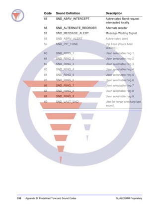
; NV-items are programmed using the nv_write command:
; nv_write itemname { [nam index,] val1, val2, ..., valn }
; Only NAM 0 has meaningful values. Values for NAMs 1-3 are
; zeroed out or set to default values.
; Some items require a nam index (0-3). The curly braces
; are required and they surround the values to be written.
; You must supply every value the item expects. Hex values
; you supply need the 0x prefix.
; Semi-colons introduce comments. Whole line and
; to-end-of-line comments are possible.
; THE FOLLOWING PARAMETERS SHOULD BE SET FOR EACH PHONE:
; ------------------------------------------------------
; 1. CDMA preferred serving system (System A or System B)
; 2. Analog preferred serving system (System A or System B)
; 3. Analog Home SID (the SID of the preferred serving system)
; 4. Analog first paging channel (for system A or system B)
; 5. CDMA primary and secondary channels (including PCN, if in
; use)
; 6. CDMA SID/NID pairs (the SID of the preferred serving system)
; 7. MIN1 and MIN2 parameters.
;================================================================
print "Start Service Programming"
; Enter the Service Programming Code (factory defaulted to 000000)
; If you don’t have version 116 or later, this command will fail.
; This allows access to the SP items (both reading _and_ writing)
spc "000000"
; Put the DMSS in offline analog mode
mode offline-a
;openlog srv_prog.log ; Uncomment if you want a log
; Display the ESN and permanent physical station
; configuration parameters
nv_read esn
nv_read verno_maj
nv_read verno_min
nv_read scm
nv_read slot_cycle_index
nv_read mob_cai_rev
nv_read mob_firm_rev
nv_read mob_model
print "Hit any key to continue"
pause
; NAM parameters.
; Preferred serving system
print "Programming CDMA Preferred Server"
nv_write cdma_pref_serv {0, "b only"}
nv_write cdma_pref_serv {1, "b only"}
nv_write cdma_pref_serv {2, "b only"}
nv_write cdma_pref_serv {3, "b only"}](https://image.slidesharecdn.com/caitusersguide-130605023737-phpapp02/85/QCTest-CDMA-Air-Interface-Tester-CAIT-3-1-User-s-Guide-330-320.jpg)


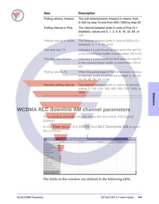
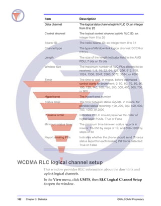
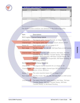
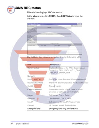
The document is the user’s guide for the Qualcomm QCTest Cait 3.1, detailing its features, system requirements, installation, and operation. It includes comprehensive instructions for signal analysis, statistics, status and control, logging, mapping, scripting, and system configuration. Additionally, it emphasizes the proprietary nature of the information and the legal restrictions on reproduction and distribution.


