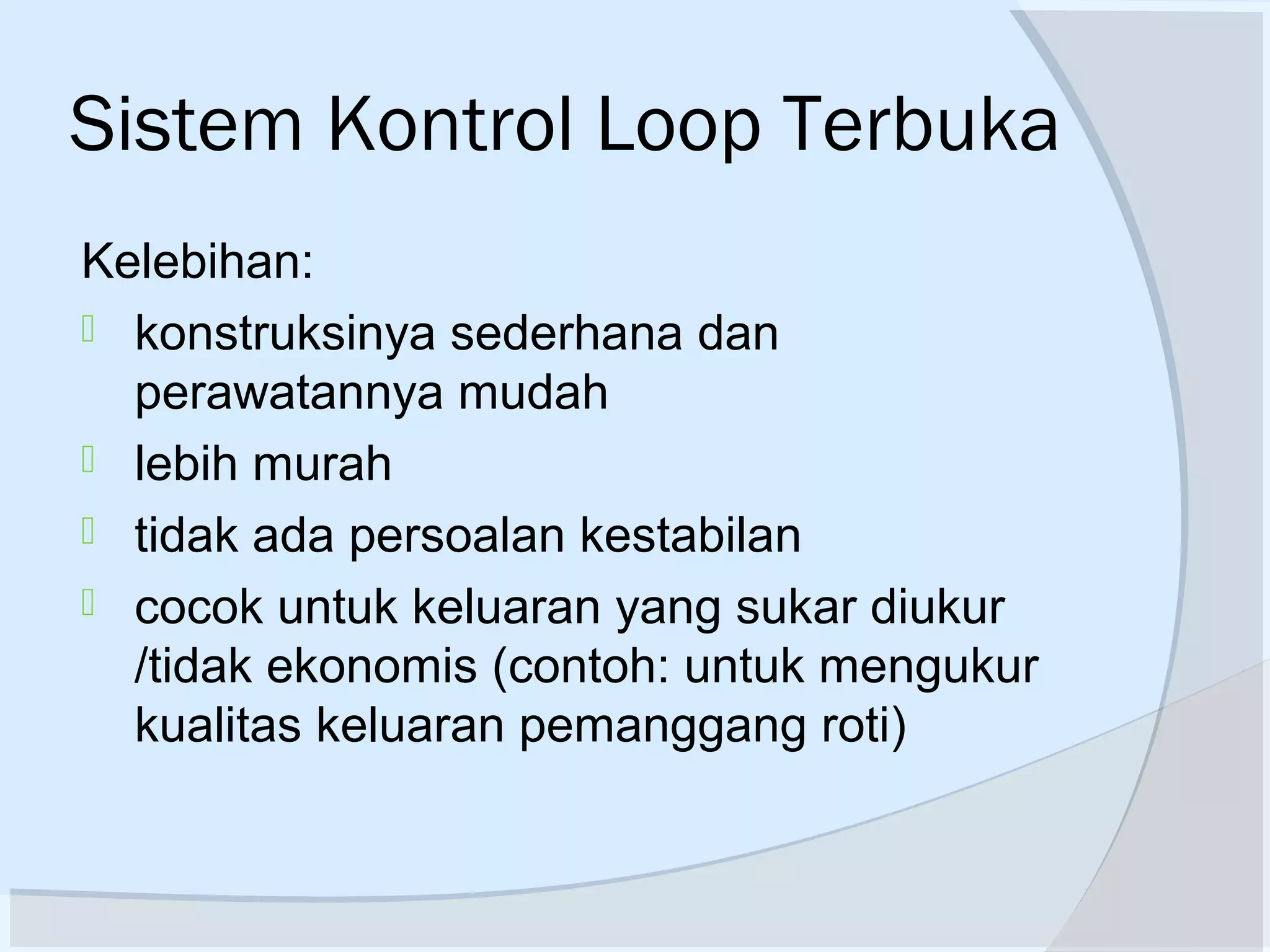
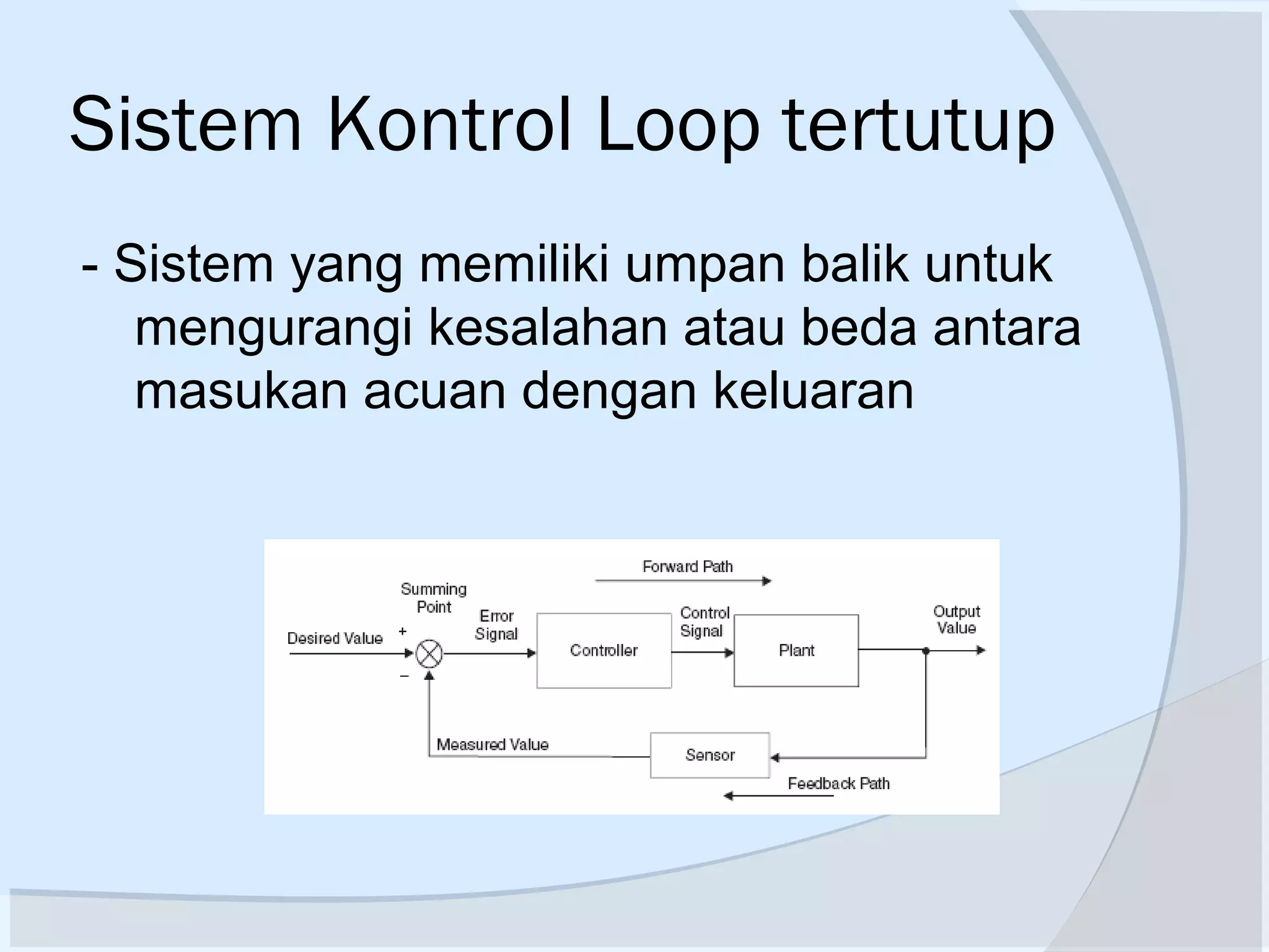
Pengenalan Sistem Kontrol
 Topik Bahasan
Konsep Dasar Sistem Kontrol
Jenis Sistem Kontrol
Contoh-contoh
Desain Sistem Kontrol
Konsep Dasar Sistem Kontrol
 Sistem = Kombinasi komponen2 yang
bekerja bersama2 untuk mencapai
tujuan tertentu (fisik atau
abstrak,biologi,ekomoni)
 Sistem Kontrol = sistem yang dapat di-
identifikasi atau ditengarai terdiri dari
minimal 2 (dua) bagian utama, yaitu:
- Plant/proses, obyek yang dikendalikan
- Kontroller/Pengendali, yang mengendalikan
Jenis Sistem Kontrol
 Secara garis besar
 Sistem Kontrol Loop terbuka
 Sistem Kontrol Loop tertutup
Sistem Kontrol Loop Terbuka
 Sistem yang kelurannya tidak mempunyai
pengaruh terhadap aksi kendali
 Keluaran sistem tidak dapat digunakan
sebagai perbandingan umpan balik dengan
masukan.
ProsesKontrollerMasukan Keluaran
Sistem Kontrol Loop Terbuka
Karakteristik Sistem kendali lup terbuka :
 output tidak diukur maupun di
umpanbalikkan
 bergantung pada kalibrasi
 hubungan antara output dan input
diketahui
 tidak ada ‘internal disturbance’ maupun
‘eksternal disturbance’
 terkait dengan waktu
Sistem Kontrol Loop Terbuka
Kelebihan:
 konstruksinya sederhana dan
perawatannya mudah
 lebih murah
 tidak ada persoalan kestabilan
 cocok untuk keluaran yang sukar diukur
/tidak ekonomis (contoh: untuk mengukur
kualitas keluaran pemanggang roti)
Sistem Kontrol Loop Terbuka
Kelemahan:
 gangguan dan perubahan kalibrasi
 untuk menjaga kualitas yang diinginkan
perlu kalibrasi ulang dari waktu ke waktu
Contoh :
- kendali traffic (lalu lintas)
- mesin cuci
Sistem Kontrol Loop tertutup
- Sistem yang memiliki umpan balik untuk
mengurangi kesalahan atau beda antara
masukan acuan dengan keluaran
Sistem Kontrol Loop tertutup
reference
input
signal,
command
isyarat
masukan
acuan,
perintah,
set-point
feedback signal
isyarat umpan-balik
output signal
luaran, isyarat
luaran, hasil,
produk
PROSES
(PLANT)
control signal
isyarat kendaliPENGENDALI
(CONTROLLE
R)
Contoh-Contoh Sistek Kontrol
 Open Loop
Pemanggang Roti Motor DC
Contoh-Contoh Sistem Kontrol
 Sistem Kontrol Kecepatan – James Watt
Plant : engine
Controlled Variable : Engine speed
Control Signal : jumlah Fuel
Contoh-Contoh Sistem Kontrol
 Kontrol Manipulator Robot
Contoh-Contoh Sistem Kontrol
 Sistem Kontrol Temperatur
Contoh-Contoh Sistem Kontrol
 Kontrol Elevator Pesawat
Contoh-Contoh Sistem Kontrol
 Sistem Kontrol Level
Contoh-Contoh Sistem Kontrol
 SK Radar Tracking Pesawat
Radar mendeteksi posisi & kec pesawat
Contoh-Contoh Sistem Kontrol
 Radar mendeteksi posisi & kec pesawat
 Dipakai komp u menentukan lead &
firing angle penembak
 Sudut2 ini diumpankan ke power amp
sebagai driver motor
 Feedback signal menjamin alignment
penembak sesuai yang diset komputer
Contoh-Contoh Sistem Kontrol
 SK Autopilot Kapal Laut
Gyro-Compas u ngitung actual heading
Autopilot hit demand rudder anglesteering
geer
Rudder menyebabkan hull(lambung kapal)
bergeser
Contoh-Contoh Sistem Kontrol
 SK Autopilot Kapal Laut
21
Road
conditions
Speed
Steering
Noise
desired direction
actual direction
Response
direction of
travel
Time
Response
speed
Time
Desired speed
Actual speed
Contoh-Contoh Sistem Kontrol
 Steering Automobile
Actual
output
Automobile
Steering
mechanism
Driver
Desired
speed or
direction
Process/
Plant
ActuatorController
Desired
output
Actual
output
Disturbance
Open-loop menggunakan actuating device untuk mengontrol process
secara langsung tanpa feedback
Kerugian : sensitivity to disturbances and system’s inability to correct
for these disturbances
Steering Automobile :
Open loop
23
Actual
output
Automobile
Steering
mechanism
Driver
Measurement
Comparison
Desired
speed or
direction
Process/
Plant
ActuatorController
Sensor
Desired
output
Actual
outputerror+
-
feedbackMeasurement output
Disturbance
SK Steering Automobile :
Close loop
24
Contoh-Contoh Sistem Kontrol
 Mesin Tenun
25
feed-eye and resin bath
Filament winding process
Mandrel
Contoh 2: Komputer Kontrol
untuk Mesin Tenun
26
Master
Computer
Sub CPU
1
2
3
4
PWM 1
PWM 2
PWM 3
PWM 4
Motor 1
Motor 2
Motor 3
Motor 4
Motion 1
Motion 2
Motion 3
Motion 4
Contoh 2: Komputer Kontrol
untuk Mesin Tenun
27
2nd Motion
control
DC/AC/step
ping motor
PWM
Unit
Optical
Encoder
Desired
position of
motion 2
Actual
position
error+
-
Feedback:
position signal
Speed feedback
Disturbance
Sub CPU
#2
Tachogenerator
Contoh 2: Komputer Kontrol
untuk Mesin Tenun
Desain Sistem Kontrol
29
Performance specifications:
 It is very important to define, in numerical terms, what
is the expected performance of the control system
 One possibility is to examine the behavior of the output
in response to a sudden change in input: known as the
“step response”
Steady state error
overshoot
Rise time
Time (s)
Output
Typical requirements:
• No overshoot
• Zero steady state error
• Rising time as small as
possible
30
Control System Design
(1) Understand the system to be controlled. Define the objectives of the
controller (establish control goals)
(2) Identify the variables to control, build a simple mathematical model of
the system and examine the system behavior. Does the model
captures essential features of the system? If not revise the model.
(3) Write the specifications for the variables
(4) System configuration: sensor, controller, actuator, etc.
(5) Developing a model of the process, the actuator, and the sensor
(6) Describe a controller, select key parameters to be adjusted.
(7) Analyze and simulate the controller. Are objectives achieved? If not,
change the control strategy and redesign
(8) Test the controller on the real system. Can the control law be “fine
tuned” to achieve desired behavior? If not iterate until a satisfactory
solution is obtained
31
Step 1: Understand the system to be controlled. Define
the objectives of the controller (establish control goals)
For example :
control goal: to control the velocity of motor accurately
or to control the direction of the motor
32
Step 2: Identify the variables to control, build a simple
mathematical model of the system and examine the
system behavior.
control variable: angular of steering wheel
mathematical model: f(v, t, P)
control variable: position of each motion
mathematical model: f(x, y, z, ϕ, v, t)
33
Step 3: Write the specifications
e.g.
 range of control variable values
 accuracy of control
 rise time of system response
 percent overshoot the response
 settling time
 peak time
 …...
34
Step 4: System configuration: choosing control system
components, which are assembled into a viable system, based upon
requirements.
Sensor: tachogenerator, optical encoder, etc.
Actuator: AC/DC servo motor with reduction gear boxes
Controller: PWM unit; microcomputer for position control
of each motion; PC used as master computer, to
control the coupling movement of several motions
Control algorithm: PID controller
Computer programming language: C++ and Assembler
35
DC motor
tachometer
Optical encoder
http://www.micromo.com/
36
Step 5: Developing a model of the process,
the actuator and the sensor.
model of the winding process
AC/DC servo motor model
Encoder and other sensor models
37
Step 6: Decide on a control strategy, select key
parameters to be adjusted.
In example 1:
possible control law: P controller
Throttle=K*(desired speed - actual speed)
In example 2:
possible control law: PID controller
∫++=
T
IDP edtKeKeKV
0

38
Step 7: Analyze and simulate the controller, and select
key parameters to be adjusted
System characteristics to be analyzed include:
 transient response
 steady-state error
 stability
 sensitivity: system behavior changes with changes in component
values or system parameters, e.g. temperature, pressure, etc.
(systems must be built so that expected changes do not degrade
performance beyond specified bounds)
 evaluation of time response of the system for a given
input
 Parameters to be adjusted: KP, KD, KI
39
Step 8: Test the controller on the real system.
Interference (Electromagnetic, noise, etc.)
Hardware and software
Controller parameters
…...
40
Step 1: Establish control goals
Step 2: Identify the variables to control
Step 3: Write the specifications for the variables
Step 4: System configuration: sensor, controller, actuator, etc.
Step 5: developing models for process, actuator, sensors
Step 6: Describe a controller, select key parameters
Review: Steps of control system design
Step 7: Analyze and simulate the controller
41
Specification: control goals, variables, etc.
Modeling and System Behavior
Controller design, PID; Root Locus analysis
Feedback systems
Time domain specifications & system stability
Frequency domain
Bode plot
Compensator design
Aspects of industrial PID State variable
Autotuning rules of PID
Analysis & design
Materi Sistem Kontrol Dasar
42
Review questions:
(1) Give examples of open-loop systems
(2) Name several applications for feedback control system
(3) Name reasons for using feedback control systems and reasons
for not using them
(4) Functionally, how do closed-loop systems differ from open-loop
systems?
(5) Name two possible control law for motion controls
(6) Name advantages of having a computer in the control loop
(7) Three major design criteria. (1) transient response, (2)steady-
state error and (3) stability. Briefly describe the criteria.
(8) Name components in a control system
(9) Briefly describe performance specifications of control systems
(10) Describe steps of a control system design.
Referensi
 Sistem Kontrol Otomasti, K Ogata
 Automatic Control System, Benjamin C
Kuo
 Advance Control Engineering, Ronald
SB
 Internet
 dll

Bag 1 pengenalan sistem kontrol

  • 2.
    Pengenalan Sistem Kontrol Topik Bahasan Konsep Dasar Sistem Kontrol Jenis Sistem Kontrol Contoh-contoh Desain Sistem Kontrol
  • 3.
    Konsep Dasar SistemKontrol  Sistem = Kombinasi komponen2 yang bekerja bersama2 untuk mencapai tujuan tertentu (fisik atau abstrak,biologi,ekomoni)  Sistem Kontrol = sistem yang dapat di- identifikasi atau ditengarai terdiri dari minimal 2 (dua) bagian utama, yaitu: - Plant/proses, obyek yang dikendalikan - Kontroller/Pengendali, yang mengendalikan
  • 4.
    Jenis Sistem Kontrol Secara garis besar  Sistem Kontrol Loop terbuka  Sistem Kontrol Loop tertutup
  • 5.
    Sistem Kontrol LoopTerbuka  Sistem yang kelurannya tidak mempunyai pengaruh terhadap aksi kendali  Keluaran sistem tidak dapat digunakan sebagai perbandingan umpan balik dengan masukan. ProsesKontrollerMasukan Keluaran
  • 6.
    Sistem Kontrol LoopTerbuka Karakteristik Sistem kendali lup terbuka :  output tidak diukur maupun di umpanbalikkan  bergantung pada kalibrasi  hubungan antara output dan input diketahui  tidak ada ‘internal disturbance’ maupun ‘eksternal disturbance’  terkait dengan waktu
  • 7.
    Sistem Kontrol LoopTerbuka Kelebihan:  konstruksinya sederhana dan perawatannya mudah  lebih murah  tidak ada persoalan kestabilan  cocok untuk keluaran yang sukar diukur /tidak ekonomis (contoh: untuk mengukur kualitas keluaran pemanggang roti)
  • 8.
    Sistem Kontrol LoopTerbuka Kelemahan:  gangguan dan perubahan kalibrasi  untuk menjaga kualitas yang diinginkan perlu kalibrasi ulang dari waktu ke waktu Contoh : - kendali traffic (lalu lintas) - mesin cuci
  • 9.
    Sistem Kontrol Looptertutup - Sistem yang memiliki umpan balik untuk mengurangi kesalahan atau beda antara masukan acuan dengan keluaran
  • 10.
    Sistem Kontrol Looptertutup reference input signal, command isyarat masukan acuan, perintah, set-point feedback signal isyarat umpan-balik output signal luaran, isyarat luaran, hasil, produk PROSES (PLANT) control signal isyarat kendaliPENGENDALI (CONTROLLE R)
  • 11.
    Contoh-Contoh Sistek Kontrol Open Loop Pemanggang Roti Motor DC
  • 12.
    Contoh-Contoh Sistem Kontrol Sistem Kontrol Kecepatan – James Watt Plant : engine Controlled Variable : Engine speed Control Signal : jumlah Fuel
  • 13.
    Contoh-Contoh Sistem Kontrol Kontrol Manipulator Robot
  • 14.
    Contoh-Contoh Sistem Kontrol Sistem Kontrol Temperatur
  • 15.
    Contoh-Contoh Sistem Kontrol Kontrol Elevator Pesawat
  • 16.
  • 17.
    Contoh-Contoh Sistem Kontrol SK Radar Tracking Pesawat Radar mendeteksi posisi & kec pesawat
  • 18.
    Contoh-Contoh Sistem Kontrol Radar mendeteksi posisi & kec pesawat  Dipakai komp u menentukan lead & firing angle penembak  Sudut2 ini diumpankan ke power amp sebagai driver motor  Feedback signal menjamin alignment penembak sesuai yang diset komputer
  • 19.
    Contoh-Contoh Sistem Kontrol SK Autopilot Kapal Laut Gyro-Compas u ngitung actual heading Autopilot hit demand rudder anglesteering geer Rudder menyebabkan hull(lambung kapal) bergeser
  • 20.
    Contoh-Contoh Sistem Kontrol SK Autopilot Kapal Laut
  • 21.
    21 Road conditions Speed Steering Noise desired direction actual direction Response directionof travel Time Response speed Time Desired speed Actual speed Contoh-Contoh Sistem Kontrol  Steering Automobile
  • 22.
    Actual output Automobile Steering mechanism Driver Desired speed or direction Process/ Plant ActuatorController Desired output Actual output Disturbance Open-loop menggunakanactuating device untuk mengontrol process secara langsung tanpa feedback Kerugian : sensitivity to disturbances and system’s inability to correct for these disturbances Steering Automobile : Open loop
  • 23.
  • 24.
  • 25.
    25 feed-eye and resinbath Filament winding process Mandrel Contoh 2: Komputer Kontrol untuk Mesin Tenun
  • 26.
    26 Master Computer Sub CPU 1 2 3 4 PWM 1 PWM2 PWM 3 PWM 4 Motor 1 Motor 2 Motor 3 Motor 4 Motion 1 Motion 2 Motion 3 Motion 4 Contoh 2: Komputer Kontrol untuk Mesin Tenun
  • 27.
    27 2nd Motion control DC/AC/step ping motor PWM Unit Optical Encoder Desired positionof motion 2 Actual position error+ - Feedback: position signal Speed feedback Disturbance Sub CPU #2 Tachogenerator Contoh 2: Komputer Kontrol untuk Mesin Tenun
  • 28.
  • 29.
    29 Performance specifications:  Itis very important to define, in numerical terms, what is the expected performance of the control system  One possibility is to examine the behavior of the output in response to a sudden change in input: known as the “step response” Steady state error overshoot Rise time Time (s) Output Typical requirements: • No overshoot • Zero steady state error • Rising time as small as possible
  • 30.
    30 Control System Design (1)Understand the system to be controlled. Define the objectives of the controller (establish control goals) (2) Identify the variables to control, build a simple mathematical model of the system and examine the system behavior. Does the model captures essential features of the system? If not revise the model. (3) Write the specifications for the variables (4) System configuration: sensor, controller, actuator, etc. (5) Developing a model of the process, the actuator, and the sensor (6) Describe a controller, select key parameters to be adjusted. (7) Analyze and simulate the controller. Are objectives achieved? If not, change the control strategy and redesign (8) Test the controller on the real system. Can the control law be “fine tuned” to achieve desired behavior? If not iterate until a satisfactory solution is obtained
  • 31.
    31 Step 1: Understandthe system to be controlled. Define the objectives of the controller (establish control goals) For example : control goal: to control the velocity of motor accurately or to control the direction of the motor
  • 32.
    32 Step 2: Identifythe variables to control, build a simple mathematical model of the system and examine the system behavior. control variable: angular of steering wheel mathematical model: f(v, t, P) control variable: position of each motion mathematical model: f(x, y, z, ϕ, v, t)
  • 33.
    33 Step 3: Writethe specifications e.g.  range of control variable values  accuracy of control  rise time of system response  percent overshoot the response  settling time  peak time  …...
  • 34.
    34 Step 4: Systemconfiguration: choosing control system components, which are assembled into a viable system, based upon requirements. Sensor: tachogenerator, optical encoder, etc. Actuator: AC/DC servo motor with reduction gear boxes Controller: PWM unit; microcomputer for position control of each motion; PC used as master computer, to control the coupling movement of several motions Control algorithm: PID controller Computer programming language: C++ and Assembler
  • 35.
  • 36.
    36 Step 5: Developinga model of the process, the actuator and the sensor. model of the winding process AC/DC servo motor model Encoder and other sensor models
  • 37.
    37 Step 6: Decideon a control strategy, select key parameters to be adjusted. In example 1: possible control law: P controller Throttle=K*(desired speed - actual speed) In example 2: possible control law: PID controller ∫++= T IDP edtKeKeKV 0 
  • 38.
    38 Step 7: Analyzeand simulate the controller, and select key parameters to be adjusted System characteristics to be analyzed include:  transient response  steady-state error  stability  sensitivity: system behavior changes with changes in component values or system parameters, e.g. temperature, pressure, etc. (systems must be built so that expected changes do not degrade performance beyond specified bounds)  evaluation of time response of the system for a given input  Parameters to be adjusted: KP, KD, KI
  • 39.
    39 Step 8: Testthe controller on the real system. Interference (Electromagnetic, noise, etc.) Hardware and software Controller parameters …...
  • 40.
    40 Step 1: Establishcontrol goals Step 2: Identify the variables to control Step 3: Write the specifications for the variables Step 4: System configuration: sensor, controller, actuator, etc. Step 5: developing models for process, actuator, sensors Step 6: Describe a controller, select key parameters Review: Steps of control system design Step 7: Analyze and simulate the controller
  • 41.
    41 Specification: control goals,variables, etc. Modeling and System Behavior Controller design, PID; Root Locus analysis Feedback systems Time domain specifications & system stability Frequency domain Bode plot Compensator design Aspects of industrial PID State variable Autotuning rules of PID Analysis & design Materi Sistem Kontrol Dasar
  • 42.
    42 Review questions: (1) Giveexamples of open-loop systems (2) Name several applications for feedback control system (3) Name reasons for using feedback control systems and reasons for not using them (4) Functionally, how do closed-loop systems differ from open-loop systems? (5) Name two possible control law for motion controls (6) Name advantages of having a computer in the control loop (7) Three major design criteria. (1) transient response, (2)steady- state error and (3) stability. Briefly describe the criteria. (8) Name components in a control system (9) Briefly describe performance specifications of control systems (10) Describe steps of a control system design.
  • 43.
    Referensi  Sistem KontrolOtomasti, K Ogata  Automatic Control System, Benjamin C Kuo  Advance Control Engineering, Ronald SB  Internet  dll

Editor's Notes

  • #22 Speed and direction control of cars: Driving an automobile is a pleasant task when the auto responds rapidly to the driver’s commands. Many cars have power steering and brakes, which utilize hydraulic amplifiers for amplification of the force to the steering wheel or brakes. The desired course or speed is compared with a measurement of the actual course or speed in order generate a measure of the error. This measurement is obtained by visual and tactile (body movement) feedback.
  • #23 An open-loop control system utilizes an actuating device to control the process directly without using feedback The disadvantages of open-loop systems, namely, sensitivity to disturbances and the system’s inability to correct for these disturbances, may be overcome in closed-loop systems. A closed-loop control system uses a measurement of the output and feedback of this signal to compare it with the desired input (reference or command) Control systems operate in a closed-loop sequence. With an accurate sensor, the measured output is equal to the actual output of the system. The difference between the desired output and the the actual output is equal to the error, which is then adjusted by the controller. The output of the controller causes the actuator to modulated the process in order to reduce the error. Negative feedback control system: the output is subtracted from the input and the difference is used as the input signal to the controller. Closed-loop systems have the obvious advantage of greater accuracy then open-loop systems. They are less sensitive to noise, disturbances, and changes in the environment.
  • #24 An open-loop control system utilizes an actuating device to control the process directly without using feedback The disadvantages of open-loop systems, namely, sensitivity to disturbances and the system’s inability to correct for these disturbances, may be overcome in closed-loop systems. A closed-loop control system uses a measurement of the output and feedback of this signal to compare it with the desired input (reference or command) Control systems operate in a closed-loop sequence. With an accurate sensor, the measured output is equal to the actual output of the system. The difference between the desired output and the the actual output is equal to the error, which is then adjusted by the controller. The output of the controller causes the actuator to modulated the process in order to reduce the error. Negative feedback control system: the output is subtracted from the input and the difference is used as the input signal to the controller. Closed-loop systems have the obvious advantage of greater accuracy then open-loop systems. They are less sensitive to noise, disturbances, and changes in the environment.
  • #30 ? How to determine the rising time? (the definition of “Rise time”)
  • #36 Optical encoder: Pos. Description 1 Circlip 2 Washer 3 Spacer 4 Ball bearing 5 Housing 6 LED support 7 LED 8 Spacer ring 9 Codewheel 10 Stator disk 11 Printed circuit 12 Cover 13 Ribbon cable 14 Connector
  • #37 As we proceed, we will notice that in every case the first step in developing a mathematical model is to apply the appropriate fundamental principles of science and engineering. For example, when we study mechanical networks, we will use Newton’s law as the fundamental guiding principles. Here, we will sum forces and torques. From these equations we will obtain the relationship between the system’s input and output.
  • #41 As we proceed, we will notice that in every case the first step in developing a mathematical model is to apply the appropriate fundamental principles of science and engineering. For example, when we study mechanical networks, we will use Newton’s law as the fundamental quiding principles. Here, we will sum forces and torques. From these equations we will obtain the relationship between the system’s input and output.
  • #42 Normally, the control system design is a one semester subject (Green line in the figure).
  • #43 As we proceed, we will notice that in every case the first step in developing a mathematical model is to apply the appropriate fundamental principles of science and engineering. For example, when we study mechanical networks, we will use Newton’s law as the fundamental quiding principles. Here, we will sum forces and torques. From these equations we will obtain the relationship between the system’s input and output.