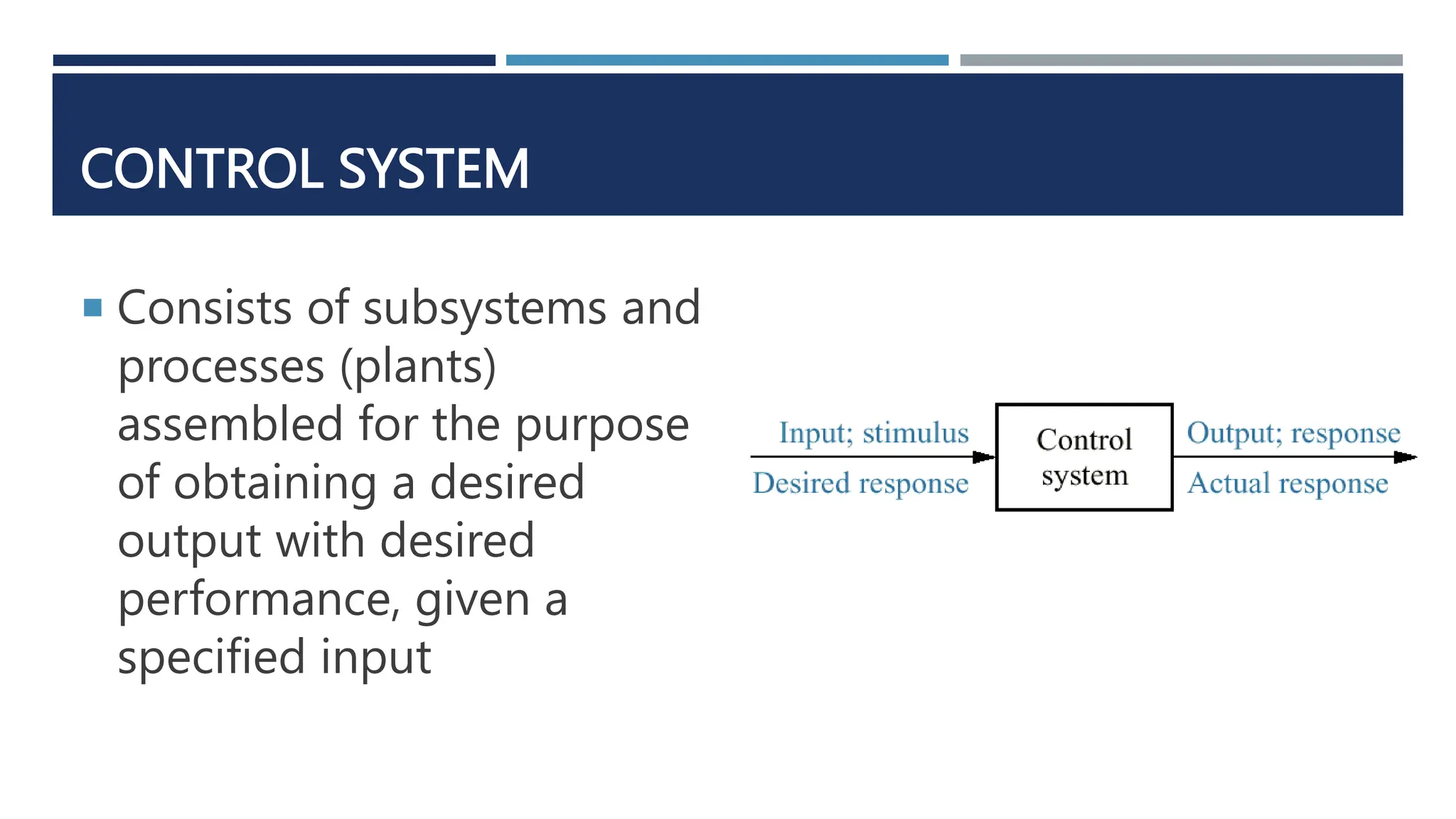
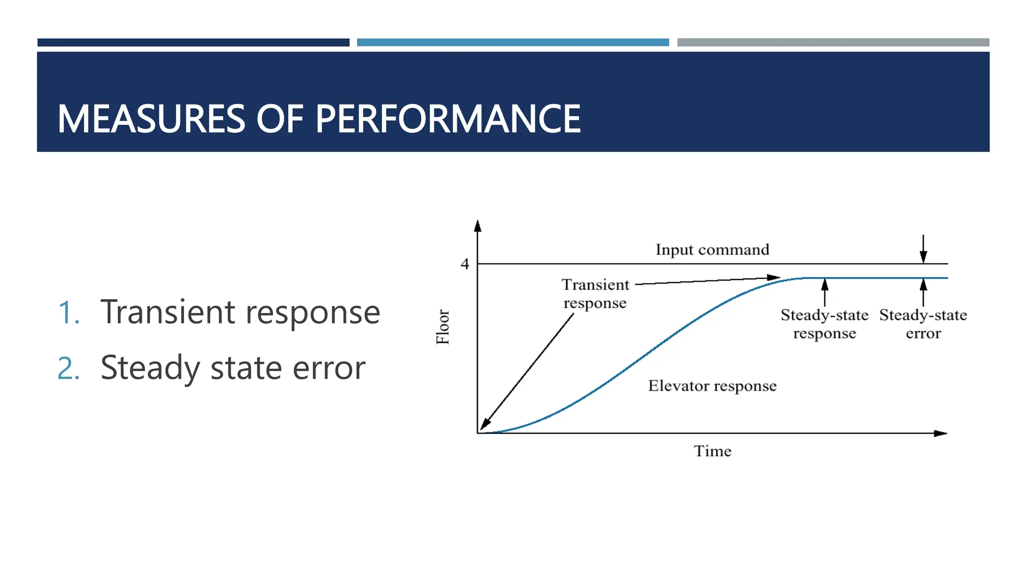
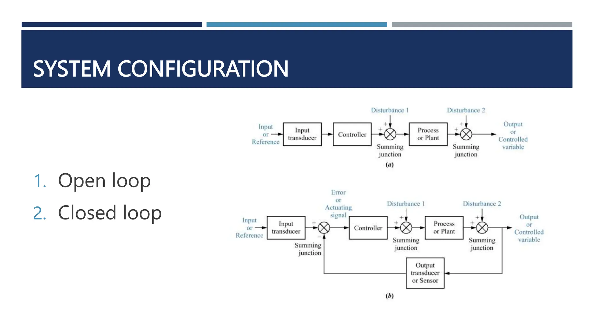
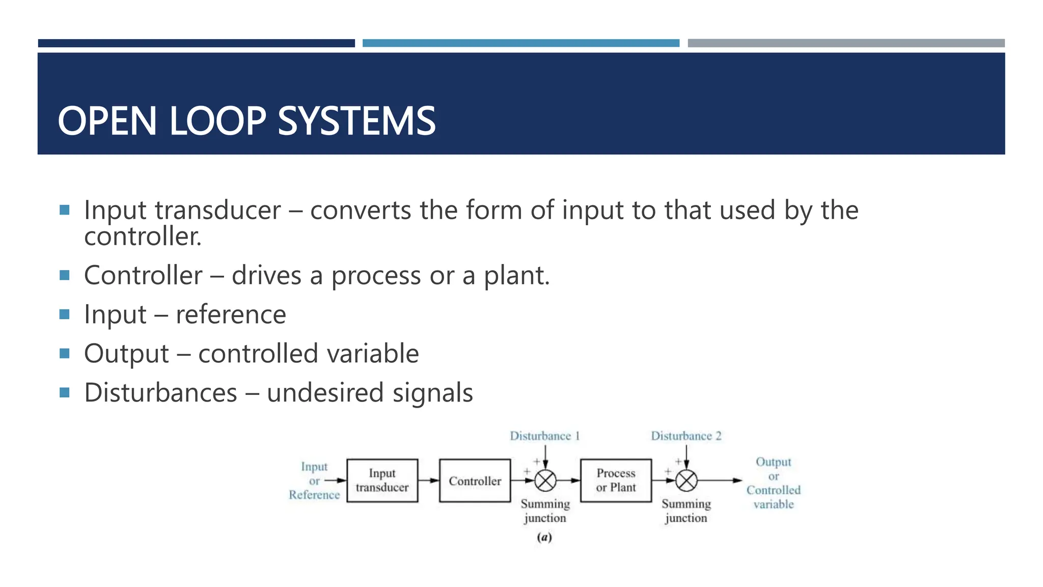
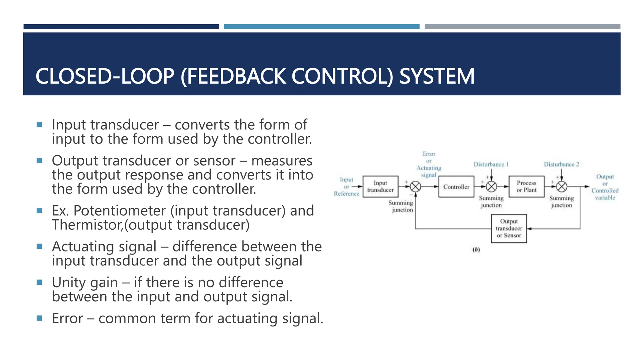
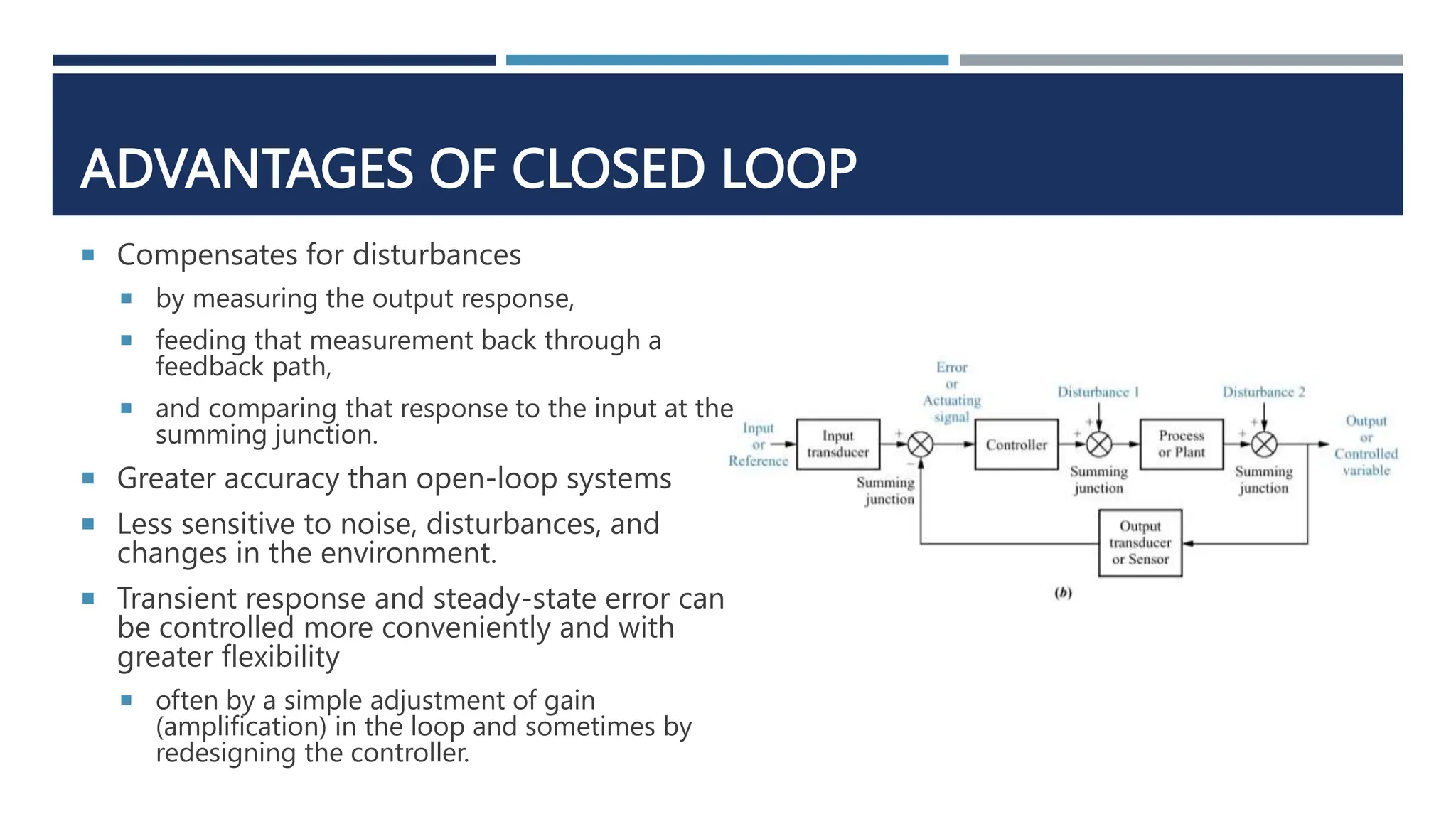
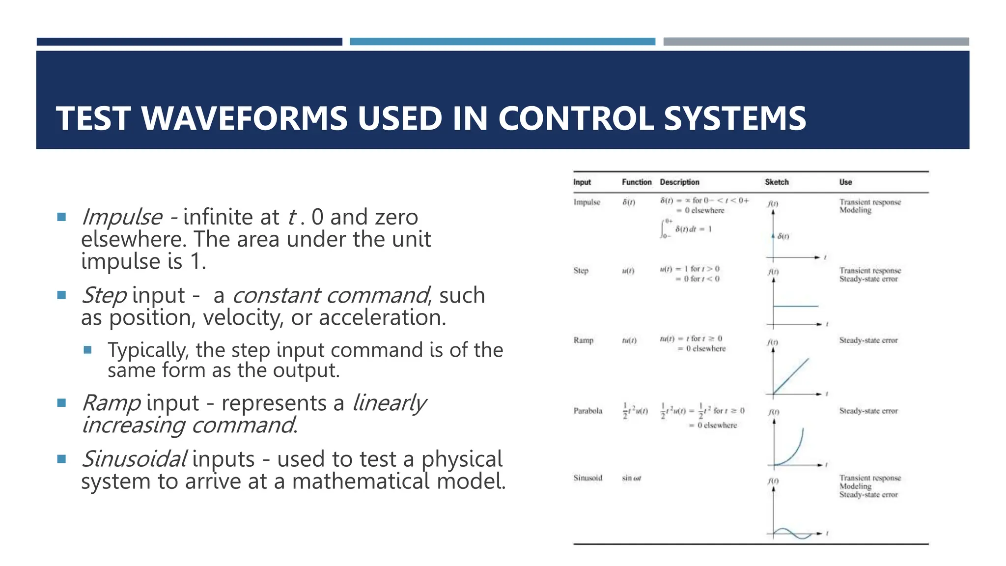
SlideShare a Scribd company logo
1 of 21
CONTROL SYSTEMS ENGINEERING
MODULE 1
ENGR. MARK JOSEPH B. ENOJAS
CONTROL SYSTEM
 Consists of subsystems and
processes (plants)
assembled for the purpose
of obtaining a desired
output with desired
performance, given a
specified input
EXAMPLES
 a. Early elevators were controlled
by hand ropes or an elevator
operator. Here, a rope is cut to
demonstrate the safety brake, an
innovation in early elevators;
 b. Modern Duo-lift elevators
make their way up the Grande
Arche in Paris, driven by one
motor, with each car
counterbalancing the other.
Today, elevators are fully
automatic, using control systems
to regulate position and velocity.
MEASURES OF PERFORMANCE
1. Transient response
2. Steady state error
ADVANTAGES OF CONTROL SYSTEMS
 Power amplification
 Remote control
 Convenience of input form
 Compensation for disturbances
EXAMPLES
 Control systems are also useful in remote or
dangerous locations.
 Rover was built to
work in contaminated areas at Three Mile Island
in Middleton, PA, where a nuclear accident
occurred in 1979. The remote controlled robot’s
long arm can be seen at the front of the vehicle.
 Control systems can also be used to provide
convenience by changing the form of the input.
A BRIEF HISTORY
 Liquid level control – 300 B.C.
 Steam pressure and temperature control – 1681 by Denis Papin by a safety valve.
 Speed Control – 1745 by Edmund Lee in a windmill.
 Stability, stabilization, and steering – 1868 by James Clerk Maxwell, the stability
criterion in third-order systems, 1874 by Edward John Routh, stability criterion in
fifth-order systems.
 Twentieth-century developments
 Automatic steering wheel in 1922 used by Sperry Gyroscope Company
 Proportional-integral-derivative (PID) control by Nicholas Minorsky
 Feedback amplifiers by Bell Laboratories in early 1930s.
APPLICATIONS
 Guidance
 Navigation
 Ammunition
 Spacecraft
 Planes
 Ships at sea
 Manufacturing
 System automation
SYSTEM CONFIGURATION
1. Open loop
2. Closed loop
OPEN LOOP SYSTEMS
 Input transducer – converts the form of input to that used by the
controller.
 Controller – drives a process or a plant.
 Input – reference
 Output – controlled variable
 Disturbances – undesired signals
DISADVANTAGES OF OPEN LOOP SYSTEM
 Cannot compensate for any disturbance that add to the
controller’s driving signal.
 Do not correct disturbance and simply commanded by the
input.
CLOSED-LOOP (FEEDBACK CONTROL) SYSTEM
 Input transducer – converts the form of
input to the form used by the controller.
 Output transducer or sensor – measures
the output response and converts it into
the form used by the controller.
 Ex. Potentiometer (input transducer) and
Thermistor,(output transducer)
 Actuating signal – difference between the
input transducer and the output signal
 Unity gain – if there is no difference
between the input and output signal.
 Error – common term for actuating signal.
ADVANTAGES OF CLOSED LOOP
 Compensates for disturbances
 by measuring the output response,
 feeding that measurement back through a
feedback path,
 and comparing that response to the input at the
summing junction.
 Greater accuracy than open-loop systems
 Less sensitive to noise, disturbances, and
changes in the environment.
 Transient response and steady-state error can
be controlled more conveniently and with
greater flexibility
 often by a simple adjustment of gain
(amplification) in the loop and sometimes by
redesigning the controller.
DISADVANTAGE OF CLOSED LOOP SYSTEMS
 More complex and expensive than open-loop systems
ANALYSIS AND DESIGN OBJECTIVES
 Analysis is the process by which a system’s performance is determined.
 Ex. Evaluation of transient response and steady-state error to determine if they
meet the desired specifications.
 Design is the process by which a system’s performance is created or
changed.
 Ex. If a system’s transient response and steady-state error are analyzed and found
not to meet the specifications, then we change parameters or add additional
components to meet the specifications.
 A control system is dynamic: It responds to an input by undergoing a
transient response before reaching a steady-state response that generally
resembles the input.
MAJOR OBJECTIVES OF SYSTEMS ANALYSIS AND DESIGN
 Transient response
 Steady-state response
 Stability
 Total response=Natural response + Forced response
 Natural response describes the way the system dissipates or acquires energy.
 dependent only on the system, not the input.
 Forced response is dependent on the input.
NATURAL RESPONSE REQUIREMENTS
1. Eventually approach zero, thus leaving only the forced
response
2. Oscillate.
 Instability happens when the natural response is so much
greater than the forced response that the system is no
longer controlled.
EXAMPLE: ANTENNA AZIMUTH POSITION CONTROL
 The purpose of this
system is to have
the azimuth angle
output of the
antenna, 𝜃0 𝑡 ,
follow the input
angle of the
potentiometer,
𝜃𝑖 𝑡 .
EXAMPLE: ANTENNA AZIMUTH POSITION CONTROL
 If the gain is increased, then for a
given actuating signal, the motor will
be driven harder.
 However, the motor will still stop when
the actuating signal reaches zero, that is,
when the output matches the input.
 The difference in the response, however,
will be in the transients.
 Since the motor is driven harder, it
turns faster toward its final position.
 Because of the increased speed,
increased momentum could cause the
motor to overshoot the final value and
be forced by the system to return to the
commanded position.
 Thus, the possibility exists for a transient
response that consists of damped
oscillations (that is, a sinusoidal response
whose amplitude diminishes with time)
about the steady-state value if the gain is
high.
THE DESIGN PROCESS
1. Transform
Requirements Into a
Physical System
2. Draw a Functional
Block Diagram
3. Create a Schematic
4. Develop a
Mathematical Model
(Block Diagram)
5. Reduce the Block
Diagram
6. Analyze and Design
TEST WAVEFORMS USED IN CONTROL SYSTEMS
 Impulse - infinite at t . 0 and zero
elsewhere. The area under the unit
impulse is 1.
 Step input - a constant command, such
as position, velocity, or acceleration.
 Typically, the step input command is of the
same form as the output.
 Ramp input - represents a linearly
increasing command.
 Sinusoidal inputs - used to test a physical
system to arrive at a mathematical model.

More Related Content

Similar to Control System Engineering by Engr Mark Joseph

Control System Design
Control System DesignControl System Design
Control System DesignHitesh Sharma
 
Modern Control - Lec 01 - Introduction to Control System
Modern Control - Lec 01 - Introduction to Control SystemModern Control - Lec 01 - Introduction to Control System
Modern Control - Lec 01 - Introduction to Control SystemAmr E. Mohamed
 
Lab1_Introduction_to_Analog_Control_Laboratory_18_12_2023.pdf
Lab1_Introduction_to_Analog_Control_Laboratory_18_12_2023.pdfLab1_Introduction_to_Analog_Control_Laboratory_18_12_2023.pdf
Lab1_Introduction_to_Analog_Control_Laboratory_18_12_2023.pdfHussamALshamaj
 
Chapter 1 basic components of control system
Chapter  1  basic components of control systemChapter  1  basic components of control system
Chapter 1 basic components of control systemHarish Odedra
 
Biomedical Control Systems - Time Response Analysis (Short Questions & Answers)
Biomedical Control Systems - Time Response Analysis (Short Questions & Answers)Biomedical Control Systems - Time Response Analysis (Short Questions & Answers)
Biomedical Control Systems - Time Response Analysis (Short Questions & Answers)Mathankumar S
 
Lecture2(introduction)
Lecture2(introduction)Lecture2(introduction)
Lecture2(introduction)Razali Tomari
 
Introduction to control system 1
Introduction to control system 1Introduction to control system 1
Introduction to control system 1turna67
 
KNL3353_Control_System_Engineering_Lectu.ppt
KNL3353_Control_System_Engineering_Lectu.pptKNL3353_Control_System_Engineering_Lectu.ppt
KNL3353_Control_System_Engineering_Lectu.pptSherAli984263
 
Introduction to control systems
Introduction to control systems Introduction to control systems
Introduction to control systems Hendi Saryanto
 
Linear control system Open loop & Close loop Systems
Linear control system Open loop & Close loop SystemsLinear control system Open loop & Close loop Systems
Linear control system Open loop & Close loop SystemsSohaibUllah5
 
What is control system
What is control systemWhat is control system
What is control systemyash7421
 
Chapter 8 - Robot Control System
Chapter 8 - Robot Control SystemChapter 8 - Robot Control System
Chapter 8 - Robot Control SystemHaffiz Radzi
 
suspension controller design using control systems
suspension controller design using control systemssuspension controller design using control systems
suspension controller design using control systemsNagamohan Burugupalli
 
Some important tips for control systems
Some important tips for control systemsSome important tips for control systems
Some important tips for control systemsmanish katara
 
CONTROL SYSTEMS.pptx
CONTROL SYSTEMS.pptxCONTROL SYSTEMS.pptx
CONTROL SYSTEMS.pptxEEEACEEC
 
Control system basics, block diagram and signal flow graph
Control system basics, block diagram and signal flow graphControl system basics, block diagram and signal flow graph
Control system basics, block diagram and signal flow graphSHARMA NAVEEN
 

Similar to Control System Engineering by Engr Mark Joseph (20)

ME416A_Module 1.pdf
ME416A_Module 1.pdfME416A_Module 1.pdf
ME416A_Module 1.pdf
 
Control System Design
Control System DesignControl System Design
Control System Design
 
Modern Control - Lec 01 - Introduction to Control System
Modern Control - Lec 01 - Introduction to Control SystemModern Control - Lec 01 - Introduction to Control System
Modern Control - Lec 01 - Introduction to Control System
 
Lab1_Introduction_to_Analog_Control_Laboratory_18_12_2023.pdf
Lab1_Introduction_to_Analog_Control_Laboratory_18_12_2023.pdfLab1_Introduction_to_Analog_Control_Laboratory_18_12_2023.pdf
Lab1_Introduction_to_Analog_Control_Laboratory_18_12_2023.pdf
 
Chapter 1 basic components of control system
Chapter  1  basic components of control systemChapter  1  basic components of control system
Chapter 1 basic components of control system
 
Biomedical Control Systems - Time Response Analysis (Short Questions & Answers)
Biomedical Control Systems - Time Response Analysis (Short Questions & Answers)Biomedical Control Systems - Time Response Analysis (Short Questions & Answers)
Biomedical Control Systems - Time Response Analysis (Short Questions & Answers)
 
Lecture2(introduction)
Lecture2(introduction)Lecture2(introduction)
Lecture2(introduction)
 
Introduction to control system 1
Introduction to control system 1Introduction to control system 1
Introduction to control system 1
 
KNL3353_Control_System_Engineering_Lectu.ppt
KNL3353_Control_System_Engineering_Lectu.pptKNL3353_Control_System_Engineering_Lectu.ppt
KNL3353_Control_System_Engineering_Lectu.ppt
 
Introduction to control systems
Introduction to control systems Introduction to control systems
Introduction to control systems
 
Linear control system Open loop & Close loop Systems
Linear control system Open loop & Close loop SystemsLinear control system Open loop & Close loop Systems
Linear control system Open loop & Close loop Systems
 
What is control system
What is control systemWhat is control system
What is control system
 
History of feedback
History of feedbackHistory of feedback
History of feedback
 
Chapter 8 - Robot Control System
Chapter 8 - Robot Control SystemChapter 8 - Robot Control System
Chapter 8 - Robot Control System
 
suspension controller design using control systems
suspension controller design using control systemssuspension controller design using control systems
suspension controller design using control systems
 
Some important tips for control systems
Some important tips for control systemsSome important tips for control systems
Some important tips for control systems
 
CONTROL SYSTEMS.pptx
CONTROL SYSTEMS.pptxCONTROL SYSTEMS.pptx
CONTROL SYSTEMS.pptx
 
REPORTTTTTT.pptx
REPORTTTTTT.pptxREPORTTTTTT.pptx
REPORTTTTTT.pptx
 
Control system basics, block diagram and signal flow graph
Control system basics, block diagram and signal flow graphControl system basics, block diagram and signal flow graph
Control system basics, block diagram and signal flow graph
 
Control Systems
Control SystemsControl Systems
Control Systems
 

Recently uploaded

Introduction to Microprocesso programming and interfacing.pptx
Introduction to Microprocesso programming and interfacing.pptxIntroduction to Microprocesso programming and interfacing.pptx
Introduction to Microprocesso programming and interfacing.pptxvipinkmenon1
 
Microscopic Analysis of Ceramic Materials.pptx
Microscopic Analysis of Ceramic Materials.pptxMicroscopic Analysis of Ceramic Materials.pptx
Microscopic Analysis of Ceramic Materials.pptxpurnimasatapathy1234
 
(MEERA) Dapodi Call Girls Just Call 7001035870 [ Cash on Delivery ] Pune Escorts
(MEERA) Dapodi Call Girls Just Call 7001035870 [ Cash on Delivery ] Pune Escorts(MEERA) Dapodi Call Girls Just Call 7001035870 [ Cash on Delivery ] Pune Escorts
(MEERA) Dapodi Call Girls Just Call 7001035870 [ Cash on Delivery ] Pune Escortsranjana rawat
 
What are the advantages and disadvantages of membrane structures.pptx
What are the advantages and disadvantages of membrane structures.pptxWhat are the advantages and disadvantages of membrane structures.pptx
What are the advantages and disadvantages of membrane structures.pptxwendy cai
 
Oxy acetylene welding presentation note.
Oxy acetylene welding presentation note.Oxy acetylene welding presentation note.
Oxy acetylene welding presentation note.eptoze12
 
Architect Hassan Khalil Portfolio for 2024
Architect Hassan Khalil Portfolio for 2024Architect Hassan Khalil Portfolio for 2024
Architect Hassan Khalil Portfolio for 2024hassan khalil
 
ZXCTN 5804 / ZTE PTN / ZTE POTN / ZTE 5804 PTN / ZTE POTN 5804 ( 100/200 GE Z...
ZXCTN 5804 / ZTE PTN / ZTE POTN / ZTE 5804 PTN / ZTE POTN 5804 ( 100/200 GE Z...ZXCTN 5804 / ZTE PTN / ZTE POTN / ZTE 5804 PTN / ZTE POTN 5804 ( 100/200 GE Z...
ZXCTN 5804 / ZTE PTN / ZTE POTN / ZTE 5804 PTN / ZTE POTN 5804 ( 100/200 GE Z...ZTE
 
Biology for Computer Engineers Course Handout.pptx
Biology for Computer Engineers Course Handout.pptxBiology for Computer Engineers Course Handout.pptx
Biology for Computer Engineers Course Handout.pptxDeepakSakkari2
 
main PPT.pptx of girls hostel security using rfid
main PPT.pptx of girls hostel security using rfidmain PPT.pptx of girls hostel security using rfid
main PPT.pptx of girls hostel security using rfidNikhilNagaraju
 
Gfe Mayur Vihar Call Girls Service WhatsApp -> 9999965857 Available 24x7 ^ De...
Gfe Mayur Vihar Call Girls Service WhatsApp -> 9999965857 Available 24x7 ^ De...Gfe Mayur Vihar Call Girls Service WhatsApp -> 9999965857 Available 24x7 ^ De...
Gfe Mayur Vihar Call Girls Service WhatsApp -> 9999965857 Available 24x7 ^ De...srsj9000
 
Call Girls Narol 7397865700 Independent Call Girls
Call Girls Narol 7397865700 Independent Call GirlsCall Girls Narol 7397865700 Independent Call Girls
Call Girls Narol 7397865700 Independent Call Girlsssuser7cb4ff
 
CCS355 Neural Network & Deep Learning Unit II Notes with Question bank .pdf
CCS355 Neural Network & Deep Learning Unit II Notes with Question bank .pdfCCS355 Neural Network & Deep Learning Unit II Notes with Question bank .pdf
CCS355 Neural Network & Deep Learning Unit II Notes with Question bank .pdfAsst.prof M.Gokilavani
 
power system scada applications and uses
power system scada applications and usespower system scada applications and uses
power system scada applications and usesDevarapalliHaritha
 
Artificial-Intelligence-in-Electronics (K).pptx
Artificial-Intelligence-in-Electronics (K).pptxArtificial-Intelligence-in-Electronics (K).pptx
Artificial-Intelligence-in-Electronics (K).pptxbritheesh05
 
College Call Girls Nashik Nehal 7001305949 Independent Escort Service Nashik
College Call Girls Nashik Nehal 7001305949 Independent Escort Service NashikCollege Call Girls Nashik Nehal 7001305949 Independent Escort Service Nashik
College Call Girls Nashik Nehal 7001305949 Independent Escort Service NashikCall Girls in Nagpur High Profile
 
Heart Disease Prediction using machine learning.pptx
Heart Disease Prediction using machine learning.pptxHeart Disease Prediction using machine learning.pptx
Heart Disease Prediction using machine learning.pptxPoojaBan
 

Recently uploaded (20)

Introduction to Microprocesso programming and interfacing.pptx
Introduction to Microprocesso programming and interfacing.pptxIntroduction to Microprocesso programming and interfacing.pptx
Introduction to Microprocesso programming and interfacing.pptx
 
Microscopic Analysis of Ceramic Materials.pptx
Microscopic Analysis of Ceramic Materials.pptxMicroscopic Analysis of Ceramic Materials.pptx
Microscopic Analysis of Ceramic Materials.pptx
 
(MEERA) Dapodi Call Girls Just Call 7001035870 [ Cash on Delivery ] Pune Escorts
(MEERA) Dapodi Call Girls Just Call 7001035870 [ Cash on Delivery ] Pune Escorts(MEERA) Dapodi Call Girls Just Call 7001035870 [ Cash on Delivery ] Pune Escorts
(MEERA) Dapodi Call Girls Just Call 7001035870 [ Cash on Delivery ] Pune Escorts
 
What are the advantages and disadvantages of membrane structures.pptx
What are the advantages and disadvantages of membrane structures.pptxWhat are the advantages and disadvantages of membrane structures.pptx
What are the advantages and disadvantages of membrane structures.pptx
 
Oxy acetylene welding presentation note.
Oxy acetylene welding presentation note.Oxy acetylene welding presentation note.
Oxy acetylene welding presentation note.
 
Architect Hassan Khalil Portfolio for 2024
Architect Hassan Khalil Portfolio for 2024Architect Hassan Khalil Portfolio for 2024
Architect Hassan Khalil Portfolio for 2024
 
ZXCTN 5804 / ZTE PTN / ZTE POTN / ZTE 5804 PTN / ZTE POTN 5804 ( 100/200 GE Z...
ZXCTN 5804 / ZTE PTN / ZTE POTN / ZTE 5804 PTN / ZTE POTN 5804 ( 100/200 GE Z...ZXCTN 5804 / ZTE PTN / ZTE POTN / ZTE 5804 PTN / ZTE POTN 5804 ( 100/200 GE Z...
ZXCTN 5804 / ZTE PTN / ZTE POTN / ZTE 5804 PTN / ZTE POTN 5804 ( 100/200 GE Z...
 
young call girls in Rajiv Chowk🔝 9953056974 🔝 Delhi escort Service
young call girls in Rajiv Chowk🔝 9953056974 🔝 Delhi escort Serviceyoung call girls in Rajiv Chowk🔝 9953056974 🔝 Delhi escort Service
young call girls in Rajiv Chowk🔝 9953056974 🔝 Delhi escort Service
 
Biology for Computer Engineers Course Handout.pptx
Biology for Computer Engineers Course Handout.pptxBiology for Computer Engineers Course Handout.pptx
Biology for Computer Engineers Course Handout.pptx
 
★ CALL US 9953330565 ( HOT Young Call Girls In Badarpur delhi NCR
★ CALL US 9953330565 ( HOT Young Call Girls In Badarpur delhi NCR★ CALL US 9953330565 ( HOT Young Call Girls In Badarpur delhi NCR
★ CALL US 9953330565 ( HOT Young Call Girls In Badarpur delhi NCR
 
Exploring_Network_Security_with_JA3_by_Rakesh Seal.pptx
Exploring_Network_Security_with_JA3_by_Rakesh Seal.pptxExploring_Network_Security_with_JA3_by_Rakesh Seal.pptx
Exploring_Network_Security_with_JA3_by_Rakesh Seal.pptx
 
main PPT.pptx of girls hostel security using rfid
main PPT.pptx of girls hostel security using rfidmain PPT.pptx of girls hostel security using rfid
main PPT.pptx of girls hostel security using rfid
 
Gfe Mayur Vihar Call Girls Service WhatsApp -> 9999965857 Available 24x7 ^ De...
Gfe Mayur Vihar Call Girls Service WhatsApp -> 9999965857 Available 24x7 ^ De...Gfe Mayur Vihar Call Girls Service WhatsApp -> 9999965857 Available 24x7 ^ De...
Gfe Mayur Vihar Call Girls Service WhatsApp -> 9999965857 Available 24x7 ^ De...
 
Call Girls Narol 7397865700 Independent Call Girls
Call Girls Narol 7397865700 Independent Call GirlsCall Girls Narol 7397865700 Independent Call Girls
Call Girls Narol 7397865700 Independent Call Girls
 
CCS355 Neural Network & Deep Learning Unit II Notes with Question bank .pdf
CCS355 Neural Network & Deep Learning Unit II Notes with Question bank .pdfCCS355 Neural Network & Deep Learning Unit II Notes with Question bank .pdf
CCS355 Neural Network & Deep Learning Unit II Notes with Question bank .pdf
 
power system scada applications and uses
power system scada applications and usespower system scada applications and uses
power system scada applications and uses
 
Artificial-Intelligence-in-Electronics (K).pptx
Artificial-Intelligence-in-Electronics (K).pptxArtificial-Intelligence-in-Electronics (K).pptx
Artificial-Intelligence-in-Electronics (K).pptx
 
College Call Girls Nashik Nehal 7001305949 Independent Escort Service Nashik
College Call Girls Nashik Nehal 7001305949 Independent Escort Service NashikCollege Call Girls Nashik Nehal 7001305949 Independent Escort Service Nashik
College Call Girls Nashik Nehal 7001305949 Independent Escort Service Nashik
 
Call Us -/9953056974- Call Girls In Vikaspuri-/- Delhi NCR
Call Us -/9953056974- Call Girls In Vikaspuri-/- Delhi NCRCall Us -/9953056974- Call Girls In Vikaspuri-/- Delhi NCR
Call Us -/9953056974- Call Girls In Vikaspuri-/- Delhi NCR
 
Heart Disease Prediction using machine learning.pptx
Heart Disease Prediction using machine learning.pptxHeart Disease Prediction using machine learning.pptx
Heart Disease Prediction using machine learning.pptx
 

Control System Engineering by Engr Mark Joseph

  • 1. CONTROL SYSTEMS ENGINEERING MODULE 1 ENGR. MARK JOSEPH B. ENOJAS
  • 2. CONTROL SYSTEM  Consists of subsystems and processes (plants) assembled for the purpose of obtaining a desired output with desired performance, given a specified input
  • 3. EXAMPLES  a. Early elevators were controlled by hand ropes or an elevator operator. Here, a rope is cut to demonstrate the safety brake, an innovation in early elevators;  b. Modern Duo-lift elevators make their way up the Grande Arche in Paris, driven by one motor, with each car counterbalancing the other. Today, elevators are fully automatic, using control systems to regulate position and velocity.
  • 4. MEASURES OF PERFORMANCE 1. Transient response 2. Steady state error
  • 5. ADVANTAGES OF CONTROL SYSTEMS  Power amplification  Remote control  Convenience of input form  Compensation for disturbances
  • 6. EXAMPLES  Control systems are also useful in remote or dangerous locations.  Rover was built to work in contaminated areas at Three Mile Island in Middleton, PA, where a nuclear accident occurred in 1979. The remote controlled robot’s long arm can be seen at the front of the vehicle.  Control systems can also be used to provide convenience by changing the form of the input.
  • 7. A BRIEF HISTORY  Liquid level control – 300 B.C.  Steam pressure and temperature control – 1681 by Denis Papin by a safety valve.  Speed Control – 1745 by Edmund Lee in a windmill.  Stability, stabilization, and steering – 1868 by James Clerk Maxwell, the stability criterion in third-order systems, 1874 by Edward John Routh, stability criterion in fifth-order systems.  Twentieth-century developments  Automatic steering wheel in 1922 used by Sperry Gyroscope Company  Proportional-integral-derivative (PID) control by Nicholas Minorsky  Feedback amplifiers by Bell Laboratories in early 1930s.
  • 8. APPLICATIONS  Guidance  Navigation  Ammunition  Spacecraft  Planes  Ships at sea  Manufacturing  System automation
  • 9. SYSTEM CONFIGURATION 1. Open loop 2. Closed loop
  • 10. OPEN LOOP SYSTEMS  Input transducer – converts the form of input to that used by the controller.  Controller – drives a process or a plant.  Input – reference  Output – controlled variable  Disturbances – undesired signals
  • 11. DISADVANTAGES OF OPEN LOOP SYSTEM  Cannot compensate for any disturbance that add to the controller’s driving signal.  Do not correct disturbance and simply commanded by the input.
  • 12. CLOSED-LOOP (FEEDBACK CONTROL) SYSTEM  Input transducer – converts the form of input to the form used by the controller.  Output transducer or sensor – measures the output response and converts it into the form used by the controller.  Ex. Potentiometer (input transducer) and Thermistor,(output transducer)  Actuating signal – difference between the input transducer and the output signal  Unity gain – if there is no difference between the input and output signal.  Error – common term for actuating signal.
  • 13. ADVANTAGES OF CLOSED LOOP  Compensates for disturbances  by measuring the output response,  feeding that measurement back through a feedback path,  and comparing that response to the input at the summing junction.  Greater accuracy than open-loop systems  Less sensitive to noise, disturbances, and changes in the environment.  Transient response and steady-state error can be controlled more conveniently and with greater flexibility  often by a simple adjustment of gain (amplification) in the loop and sometimes by redesigning the controller.
  • 14. DISADVANTAGE OF CLOSED LOOP SYSTEMS  More complex and expensive than open-loop systems
  • 15. ANALYSIS AND DESIGN OBJECTIVES  Analysis is the process by which a system’s performance is determined.  Ex. Evaluation of transient response and steady-state error to determine if they meet the desired specifications.  Design is the process by which a system’s performance is created or changed.  Ex. If a system’s transient response and steady-state error are analyzed and found not to meet the specifications, then we change parameters or add additional components to meet the specifications.  A control system is dynamic: It responds to an input by undergoing a transient response before reaching a steady-state response that generally resembles the input.
  • 16. MAJOR OBJECTIVES OF SYSTEMS ANALYSIS AND DESIGN  Transient response  Steady-state response  Stability  Total response=Natural response + Forced response  Natural response describes the way the system dissipates or acquires energy.  dependent only on the system, not the input.  Forced response is dependent on the input.
  • 17. NATURAL RESPONSE REQUIREMENTS 1. Eventually approach zero, thus leaving only the forced response 2. Oscillate.  Instability happens when the natural response is so much greater than the forced response that the system is no longer controlled.
  • 18. EXAMPLE: ANTENNA AZIMUTH POSITION CONTROL  The purpose of this system is to have the azimuth angle output of the antenna, 𝜃0 𝑡 , follow the input angle of the potentiometer, 𝜃𝑖 𝑡 .
  • 19. EXAMPLE: ANTENNA AZIMUTH POSITION CONTROL  If the gain is increased, then for a given actuating signal, the motor will be driven harder.  However, the motor will still stop when the actuating signal reaches zero, that is, when the output matches the input.  The difference in the response, however, will be in the transients.  Since the motor is driven harder, it turns faster toward its final position.  Because of the increased speed, increased momentum could cause the motor to overshoot the final value and be forced by the system to return to the commanded position.  Thus, the possibility exists for a transient response that consists of damped oscillations (that is, a sinusoidal response whose amplitude diminishes with time) about the steady-state value if the gain is high.
  • 20. THE DESIGN PROCESS 1. Transform Requirements Into a Physical System 2. Draw a Functional Block Diagram 3. Create a Schematic 4. Develop a Mathematical Model (Block Diagram) 5. Reduce the Block Diagram 6. Analyze and Design
  • 21. TEST WAVEFORMS USED IN CONTROL SYSTEMS  Impulse - infinite at t . 0 and zero elsewhere. The area under the unit impulse is 1.  Step input - a constant command, such as position, velocity, or acceleration.  Typically, the step input command is of the same form as the output.  Ramp input - represents a linearly increasing command.  Sinusoidal inputs - used to test a physical system to arrive at a mathematical model.