Download to read offline
![P. Rajeepriyanka Int. Journal of Engineering Research and Applications www.ijera.com
ISSN : 2248-9622, Vol. 4, Issue 8( Version 2), August 2014, pp.09-13
www.ijera.com 13 | P a g e
REFERENCES [1] Zhi-Wei Chen and Jin-Tai Yan, Routability- Driven Flip-Flop Merging Process for Clock Power Reduction, Computer Design (ICCD) IEEE International Conference, 2010 [2] Ya-Ting Shyuet. Al., Effective and Efficient Approach for Power Reduction by Using Muti-Bit Flip-Flops, IEEE transactions on very large scale integration systems, 2012 [3] Jin-Tai Yan and Zhi-Wei Chen, Construction of Constrained Multi-Bit Flip- Flops for Clock Power Reduction, Green Circuits and Systems (ICGCS) International Conference, 2010 [4] Chih-Cheng Hsu, Yao-Tsung Chang and Mark Po-Hung Lin, Crosstalk-Aware Power Optimization with Multi-Bit Flip-Flops, 17th Asia and South Pacific Design Automation Conference, 2012 [5] Himanshu Patel; Sanjay Trivedi; R. Neelkanthan; V. R. Gujraty; , "A Robust UART Architecture Based on Recursive Running Sum Filter for Better Noise Performance," VLSI Design, 2007. Held jointly with 6th International Conference on Embedded Systems., 20th International Conference on , vol., no., pp.819-823, Jan. 2007. [6] Fang Yi-yuan; Chen Xue-jun; , "Design and Simulation of UART Serial Communication Module Based on VHDL," Intelligent Systems and Applications (ISA), 2011 3rd International Workshop on , vol.,no., pp.1-4, 28-29 May 2011 [7] Idris, M.Y.I.; Yaacob, M.;, "A VHDL implementation of BIST technique in UART design," TENCON 2003. Conference on Convergent Technologies for Asia-Pacific Region , vol.4, no., pp. 1450- 1454 Vol.4, 15-17 Oct. 2003. [8] Chun-zhi, He; Yin-shui, Xia; Lun-yao, Wang; , "A universal asynchronous receiver transmitter design," Electronics, Communications and Control (ICECC), 2011 International Conference on , vol., no., pp.691-694, 9-11 Sept. 2011](https://image.slidesharecdn.com/b48020913-140910232125-phpapp02/85/Achieving-Reduced-Area-and-Power-with-Multi-Bit-Flip-Flop-When-Implemented-In-UART-with-Status-Register-5-320.jpg)

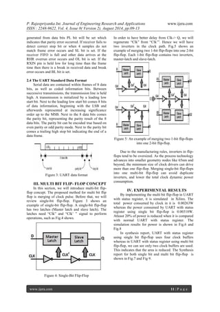
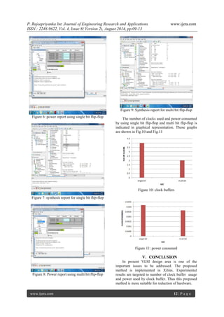
The document discusses the implementation of a Universal Asynchronous Receiver Transmitter (UART) using a multi-bit flip-flop, focusing on its efficiency in power and area reduction compared to single-bit flip-flops. It highlights the advantages of merging flip-flops to reduce redundant inverters, thereby achieving significant power savings while maintaining functionality. Experimental results indicate that the multi-bit flip-flop design reduces power consumption by at least 20% and minimizes the number of clock buffers used.