Introduction uart protocol , soc to soc communication
1.
Mahesh Awati
Department ofElectronics and Communication Engg.
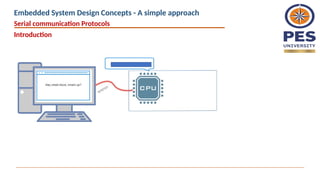
Embedded System Design Concepts
A simple approach
2.
Embedded System DesignConcepts - A simple approach
Mahesh Awati
Department of Electronics and Communication Engineering
Serial communication Protocols : UART
What is SerialCommunication
In embedded systems, the communication means the exchange
of data between two devices like Microcontrollers in the form
of bits. This exchange of data bits in between devices is done
by some set of defined rules known as communication
protocols.
The data can be communicated
As Set of bits – In Parallel between two devices.
Example: Sending a 8 bit value using a PORT to 8
LEDs connected using 8 parallel conducting paths
As bit by bit - In Serial as one bit after the other then
the communication protocol is known as Serial
Communication Protocol. More specifically, the data
bits are transmitted one at a time in sequential
manner over the data bus or communication channel
in Serial Communication.
Example: Sending a 8 bit value using a Single
PORT pin and displaying on a Single LED sequentially
D0
D1
D2
D3
D4
D5
D6
D7
D0
D1
D2
D3
D4
D5
D6
D7
Transmitter Receiver
Transmitter Receiver
D0 DI
1 (MSB)
0
1
1
0
0
1
0 (LSB)
MSB LSB
1 0 1 1 0 0 1 0
Serial communication Protocols
Embedded System Design Concepts - A simple approach
5.
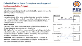
Basic Terminologies
A Serialcommunication protocols used in Embedded System may have the
following Mode of Transmission
Simplex Method:
In simplex method either of the medium i.e sender or receiver can be act
as a Transmitter. So if the sender is transmitting the data then receiver can
only accept. So simplex method is one-way communication technique.
Examples: Television and Radio.
Duplex Method:
In Duplex , Either of the medium can act as a Transmitter or Receiver. In
this gain based to connection they are classified as
Half Duplex: The Tran-receivers are connected through a Single conducting
path, As a result at a given point of time one of them acts as Transmitter
and other as Receiver . So if the sender is transmitting then receiver can
accept but cannot send and similarly vice versa.
Full Duplex: The Tran-receivers are cross connected i.e., TXD to RXD on
both ends. It means they can simultaneously Transmit and Receive the
data using separate set of conducting paths.
Serial communication Protocols
Embedded System Design Concepts - A simple approach
6.
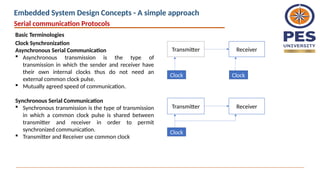
Basic Terminologies
Clock Synchronization
AsynchronousSerial Communication
Asynchronous transmission is the type of
transmission in which the sender and receiver have
their own internal clocks thus do not need an
external common clock pulse.
Mutually agreed speed of communication.
Synchronous Serial Communication
Synchronous transmission is the type of transmission
in which a common clock pulse is shared between
transmitter and receiver in order to permit
synchronized communication.
Transmitter and Receiver use common clock
Transmitter Receiver
Clock Clock
Transmitter Receiver
Clock
Serial communication Protocols
Embedded System Design Concepts - A simple approach
7.
Basic Terminologies
Point toPoint, Multi Drop and Multi Point
Point to Point: Interface between devices having
peer relationship i.e., When there is a single
dedicated link only between two devices, it is a
point-to-point connection.
Example: RS-232
Multi Drop : One Transmitter communicating
with Multiple Receivers.
Example: RS-422
Multi Point: Several Devices communicating
with several receivers. It is the interfaces capable
of internetworking multiple transmitters and
receivers in the same network.
Serial communication Protocols
Embedded System Design Concepts - A simple approach
8.
August 26, 20258
Serial Communication Standards
Onboard Communication Interfaces
These are used for internal communication of data
in a embedded system.
Used for communication between different
components present on the system.
Universal Asynchronous Receiver Transmitter (UART)
Serial Peripheral Interface (SPI)
Inter Integrated Circuit (I2C)
Controller Area Network (CAN)
1-Wire Interface, Parallel Interface
Peripheral Communication Interfaces
These are used for external communication of
the embedded system i.e: communication of
different components present on the system with
external or peripheral components/devices.
Common examples of external interfaces are:
RS-232 & RS-485
Universal Serial Bus (USB)
Bluetooth
Wi-Fi
Zig Bee
Serial communication Protocols
Embedded System Design Concepts - A simple approach
9.
UART – UniversalAsynchronous Receiver and Transmitter
Universal – As the Frame (data size ) and the speed with the data communicated are
configurable to meet the need of given communication requirements, Therefore it is
referred as Universal
UART is a Simple Half duplex , Asynchronous Serial communication protocol used fro
point to point communication. It communicates the data using a defined baud rate.
In UART, the data is Transmitted from TxD pin of Transmitter to RxD pin of Receiver
and It is Duplex in nature on both side TxD and RxD available. These pins are
operating with TTL logic
Serial communication Protocols
Embedded System Design Concepts - A simple approach
10.
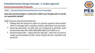
How data Synchronizationis achieved in UART even though both Tx and Rx
are separately clocked?
UART achieves data synchronisation by
Making both the devices to agree on common speed of data transfer
which is managed with a separate module called baud rate generator.
Baud-rate generators on both side are configured to generate same
standard baurates like 1200,2400,4800,9600 and 19200 so on.
Synchronisation Bits – Along with the data bits , other bits are sent to
enable synchronization of data. These include start bit, stop bit(s) and
parity bit.
Serial communication Protocols
UART – Universal Asynchronous Receiver and Transmitter
Embedded System Design Concepts - A simple approach
11.
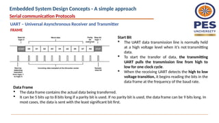
Start Bit
TheUART data transmission line is normally held
at a high voltage level when it’s not transmitting
data.
To start the transfer of data, the transmitting
UART pulls the transmission line from high to
low for one clock cycle.
When the receiving UART detects the high to low
voltage transition, it begins reading the bits in the
data frame at the frequency of the baud rate.
Data Frame
The data frame contains the actual data being transferred.
It can be 5 bits up to 8 bits long if a parity bit is used. If no parity bit is used, the data frame can be 9 bits long. In
most cases, the data is sent with the least significant bit first.
FRAME
Serial communication Protocols
UART – Universal Asynchronous Receiver and Transmitter
Embedded System Design Concepts - A simple approach
12.
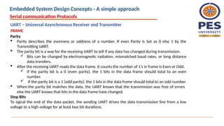
Parity
Parity describesthe evenness or oddness of a number. If even Parity is Set as 0 else 1 by the
Transmitting UART.
The parity bit is a way for the receiving UART to tell if any data has changed during transmission.
Bits can be changed by electromagnetic radiation, mismatched baud rates, or long distance
data transfers.
After the receiving UART reads the data frame, it counts the number of 1’s in frame is Even or Odd.
If the parity bit is a 0 (even parity), the 1 bits in the data frame should total to an even
number.
If the parity bit is a 1 (odd parity), the 1 bits in the data frame should total to an odd number.
When the parity bit matches the data, the UART knows that the transmission was free of errors
else the UART knows that bits in the data frame have changed.
Stop Bits
To signal the end of the data packet, the sending UART drives the data transmission line from a low
voltage to a high voltage for at least two bit durations.
Serial communication Protocols
FRAME
UART – Universal Asynchronous Receiver and Transmitter
Embedded System Design Concepts - A simple approach
13.
P 7 65 4 3 2 1 0
Transmit Register
Receive Register
Shift Register
Shift Register
TxD
RxD
Baudrate
Generator
(BRG)
Clock
0 1 2 3 4 5 6 7 P
BRG Registers
Control Register
STOP
START
STOP
START
UART
RxD
TxD
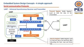
UART Transmit Register: Buffer Register
used to hold the data to be
Transmitted
Receive Register: Buffer Register used
to hold the data to be Received after
discarding the Start, stop and Parity
bit
Status Register
Serial communication Protocols
UART – Universal Asynchronous Receiver and Transmitter
Embedded System Design Concepts - A simple approach
14.
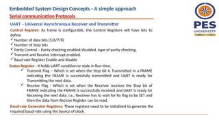
Control Register: Asframe is configurable, the Control Registers will have bits to
define
Number of data bits (5/6/7/8)
Number of Stop bits
Parity Control – Parity checking enabled/disabled, type of parity checking.
Transmit and Receive Interrupt enabled.
Baud-rate Register Enable and disable
Status Register : It holds UART condition or state in Run time.
Transmit Flag – Which is set when the Stop bit is Transmitted in a FRAME
indicating the FRAME is successfully transmitted and UART is ready for
Transmitting the next data.
Receive Flag - Which is set when the Receiver receives the Stop bit of
FRAME indicating the FRAME is successfully received and UART is ready for
Receiving the next data. i.e., Receiver has to wait for Rx flag to be SET and
then the data from Receive Register can be read.
Baud-rate Generator Registers: These registers need to be initialised to generate the
required baud-rate using the Source of clock.
Serial communication Protocols
UART – Universal Asynchronous Receiver and Transmitter
Embedded System Design Concepts - A simple approach
15.
Transistor –Transistor Logic(TTL) & Recommended Standard 232 (RS-232)
Most microcontrollers these days have built in UARTs (universally asynchronous
receiver/transmitter) that can be used to receive and transmit data serially.
The data transmitted or received through TxD and RxD pin are with TTL logic.
Serial communication at a TTL level will always remain between the limits of 0V
and Vcc, which is often 5V or 3.3V.
A logic high ('1') is represented by Vcc, while a logic low ('0') is 0V.
In RS-232 standard, the Logic levels are anything from +/- 3V to +/- 25V.
Logic 1 : [-3 to -25]V and Logic 0: [+3 to +25] V
These Logic level makes the serial communication more Susceptibility to
external conditions
RS232 more extreme voltages help make it less susceptible to noise,
interference, and degradation.
Serial communication Protocols
UART – Universal Asynchronous Receiver and Transmitter
Embedded System Design Concepts - A simple approach
16.
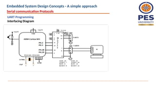
Interfacing a Modemwith Microcontroller : Null Modem Connection
A Microcontroller can be interfaced with PC using UART but the inbuilt UART
supports TTL logic and where in PC/ Modem might be supporting RS232 logic.
Therefore a Level shifter is needed which can shift the TTL logic to RS232 logic on
Microcontroller side so that the communication is done using RS232 logic.
The connection between the MCU and PC is done through RS232 cable.
A MAX232 is a IC which converts TTL logic to RS232 logic. A single IC has two Level
shifters which can be used for Two UARTs in a MCU
Serial communication Protocols
UART – Universal Asynchronous Receiver and Transmitter
Embedded System Design Concepts - A simple approach
17.
What's Wrong withSerial Ports?
It is Asynchronous , there is No guarantee that both sides are running at precisely
with the same baud rate as the Clock sources are different.
Since computers normally rely on everything being synchronized to a single
“clock” (the main crystal attached to a computer that drives everything), this can
be a problem when two systems with slightly different clocks try to communicate
with each other.
In order to work around this problem, asynchronous serial connections add extra
start and stop bits to each byte help the receiver sync up to data as it arrives.
Slight differences in the transmission rate aren't a problem because the receiver
re-syncs at the start of each byte.
The additional Start and stop bits for every byte lead to lot of overhead required
to send and receive data and a complex hardware is required.
If both sides aren't set to the same speed, the received data will be garbage. This
is because the receiver is sampling the bits at very specific times. If the receiver is
looking at the wrong times, it will see the wrong bits.
Serial communication Protocols
UART – Universal Asynchronous Receiver and Transmitter
Embedded System Design Concepts - A simple approach
18.
Synchronous -The clock is an oscillating signal that tells the receiver exactly when
to sample the bits on the data line. This could be the rising (low to high) or falling
(high to low) edge of the clock signal; the datasheet will specify which one to use.
When the receiver detects that edge, it will immediately look at the data line to
read the next bit (see the arrows in the below diagram).
08/26/2025 18
Synchronous Serial Communication
Serial communication Protocols
UART – Universal Asynchronous Receiver and Transmitter
Embedded System Design Concepts - A simple approach
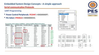
Power ControlPeripherals: PCONP|=0X000000FF;
Pin Select :PINSEL0|=0X00000050;
Serial communication Protocols
UART Programming
Embedded System Design Concepts - A simple approach
21.
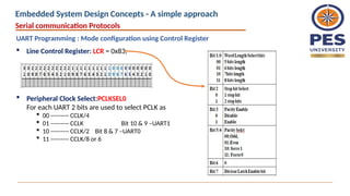
Line ControlRegister: LCR = 0x83;
Serial communication Protocols
UART Programming : Mode configuration using Control Register
Peripheral Clock Select:PCLKSEL0
For each UART 2 bits are used to select PCLK as
00 --------- CCLK/4
01 --------- CCLK Bit 10 & 9 –UART1
10 --------- CCLK/2 Bit 8 & 7 –UART0
11 --------- CCLK/8 or 6
Embedded System Design Concepts - A simple approach
22.
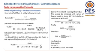
CPU_CLOCK
(CCLK) = 72MHz
Peripheral
CLKDivider
PCLKSEL0 DLM
CLKDIV bits in ADCCR
18M
04
DLL FDR
void uart0_init(void)
{
LPC_UART0->LCR = 0x83;
LPC_UART0->DLM=0X00;
LPC_UART0->DLL=0X75;
LPC_UART0->FDR=0X00000010;
LPC_UART0->LCR=0X03;
}
Serial communication Protocols
UART Programming – Baud rate Generation
Embedded System Design Concepts - A simple approach
Serial communication Protocols
UARTProgramming – Baud rate Generation
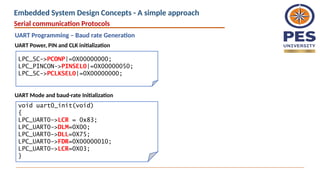
LPC_SC->PCONP|=0X00000000;
LPC_PINCON->PINSEL0|=0X00000050;
LPC_SC->PCLKSEL0|=0X00000000;
void uart0_init(void)
{
LPC_UART0->LCR = 0x83;
LPC_UART0->DLM=0X00;
LPC_UART0->DLL=0X75;
LPC_UART0->FDR=0X00000010;
LPC_UART0->LCR=0X03;
}
UART Power, PIN and CLK initialization
UART Mode and baud-rate Initialization
Embedded System Design Concepts - A simple approach
25.
UARTn Receiver BufferRegister (RBR )
The UnRBR is the top byte of the UARTn Rx FIFO.
The top byte of the Rx FIFO contains the oldest character received and can be read via
the bus interface.
The LSB (bit 0)represents the “oldest” received data bit.
If the character received is less than 8 bits, the unused MSBs are padded with zeroes.
The Divisor Latch Access Bit (DLAB) in LCR must be zero in order to access the UnRBR.
The UnRBR is always read-only.
UARTn Transmit Holding Register (THR -)
The UnTHR is the top byte of the UARTn TX FIFO.
The top byte is the newest character in the TX FIFO and can be written via the bus
interface. The LSB represents the first bit to transmit.
The Divisor Latch Access Bit (DLAB) in UnLCR must be zero in order to access the UnTHR.
The UnTHR is always write-only.
Serial communication Protocols
UART Programming – Baud rate Generation
Embedded System Design Concepts - A simple approach
26.
Line Status Register(LSR)
Serial communication Protocols
UART Programming – Baud rate Generation
Embedded System Design Concepts - A simple approach
27.
#include<LPC17XX.H>
void uart0_init(void);
void delay(unsignedlong int x);
int main()
{
unsigned char str1[]=“ ARM Cortex M3",i;
SystemInit();
LPC_PINCON->PINSEL0|=0X00000050;
uart0_init();
for(i=0;str1[i]!='0';i++)
{
LPC_UART0->THR=str1[i];
while (LPC_UART0->LSR&0xFF==0X20);
delay(100000);
}
}
void uart0_init(void)
{
LPC_UART0->LCR = 0x83;
LPC_UART0->DLM=0X00;
LPC_UART0->DLL=0X75;
LPC_UART0->FDR=0X00000010;
LPC_UART0->LCR=0X03;
}
void delay(unsigned long int x)
{
unsigned long int j;
for(j=0;j<x;j++)
{}
}
Serial communication Protocols
UART Programming
Example : Transmitting a string
Embedded System Design Concepts - A simple approach
28.
UART is usedfor
Interfacing Microcontroller with Modules like
RFID Card reader,
GSM,
GPS ,
XBee-S2
Finger Print Scanner and so on based the requirements of the
application..
Serial communication Protocols
Embedded System Design Concepts - A simple approach


![Transistor –Transistor Logic (TTL) & Recommended Standard 232 (RS-232)
Most microcontrollers these days have built in UARTs (universally asynchronous
receiver/transmitter) that can be used to receive and transmit data serially.
The data transmitted or received through TxD and RxD pin are with TTL logic.
Serial communication at a TTL level will always remain between the limits of 0V
and Vcc, which is often 5V or 3.3V.
A logic high ('1') is represented by Vcc, while a logic low ('0') is 0V.
In RS-232 standard, the Logic levels are anything from +/- 3V to +/- 25V.
Logic 1 : [-3 to -25]V and Logic 0: [+3 to +25] V
These Logic level makes the serial communication more Susceptibility to
external conditions
RS232 more extreme voltages help make it less susceptible to noise,
interference, and degradation.
Serial communication Protocols
UART – Universal Asynchronous Receiver and Transmitter
Embedded System Design Concepts - A simple approach](https://image.slidesharecdn.com/uart-250826045318-e21621b7/85/Introduction-uart-protocol-soc-to-soc-communication-15-320.jpg)


![#include<LPC17XX.H>
void uart0_init(void);
void delay(unsigned long int x);
int main()
{
unsigned char str1[]=“ ARM Cortex M3",i;
SystemInit();
LPC_PINCON->PINSEL0|=0X00000050;
uart0_init();
for(i=0;str1[i]!='0';i++)
{
LPC_UART0->THR=str1[i];
while (LPC_UART0->LSR&0xFF==0X20);
delay(100000);
}
}
void uart0_init(void)
{
LPC_UART0->LCR = 0x83;
LPC_UART0->DLM=0X00;
LPC_UART0->DLL=0X75;
LPC_UART0->FDR=0X00000010;
LPC_UART0->LCR=0X03;
}
void delay(unsigned long int x)
{
unsigned long int j;
for(j=0;j<x;j++)
{}
}
Serial communication Protocols
UART Programming
Example : Transmitting a string
Embedded System Design Concepts - A simple approach](https://image.slidesharecdn.com/uart-250826045318-e21621b7/85/Introduction-uart-protocol-soc-to-soc-communication-27-320.jpg)