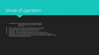
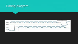
UART
Serial communication
Satyam Sharma
Sireesha Yettella
Jude Abraham
Course
Description
Parallel Communication W.R.T Serial communication
Why serial communication
Basic of UART
Message Packet Format of UART
Description of Flow Control Pins
Baud Rate
Mode of Operation
Steps to Perform UART communication
Timing diagram
Advantage and Disadvance of UART
Parallel Communication W.R.T Serial
communication
 Before understanding Serial Communication let look what is
advantage/disadvange of Parallel communication
 Parallel communication : Art of conveying multiple bits simultanesouly with
respect to clock
 Serial communication : Art of sending single bit at a time
 Differences : Parrallel communication uses no’s of channel to convey data
Eg. 8 bit pararrel channel will convey 8 bits at a time,whereas serial channel
would only use 1 channel but sequentially
 Advantage of parrel communication : Data processing speed way faster
then Serial communication eg, memory devices such as RAM
 Disadvantage of parallel communication :Cost with respect to conducting
channels
Why serial
communication
Simplest form of communication between sender and receiver by sending bits
sequentially wrt clock.
Can resolve synchronization issue faced in parallel communication
Cost effective needs less channels to stream the data between receiver and sender
Best for long distance communication.
Better signal integrity
BASIC OF UART (Universal Asynchronous
Receiver/Transmitter)
 UART basic principal is to convert the parallel data from
the controlling device such as CPU then converts the
data into serial and sends (TX)to receiver (RX) then the
data is further processed to parallel form to controlling
device to execute/process the data.
 UARTs transmit data asynchronously, which means there
is no clock signal to synchronize the output of bits from
the transmitting UART to the sampling of bits by the
receiving UART. Instead of a clock signal, the transmitting
UART adds start and stop bits to the data packet being
transferred. These bits define the beginning and end of
the data packet so the receiving UART knows when to
start reading the bits.
 Both UARTs must also must be configured to transmit
and receive the same data packet structure.
Message Packet Format of UART
 Start bit : The UART data transmission line is normally held at a high voltage level when it’s not
transmitting data. To start the transfer of data, the transmitting UART pulls the transmission line
from high to low for one clock cycle. When the receiving UART detects the high to low voltage
transition, it begins reading the bits in the data frame at the frequency of the baud rate.
 Data Frame :The data frame contains the actual data being transferred. It can be 5 bits up to 8
bits long if a parity bit is used. If no parity bit is used, the data frame can be 9 bits long. In most
cases, the data is sent with the least significant bit first.
 Parity bit :Parity describes the evenness or oddness of a number. The parity bit is a way for the
receiving UART to tell if any data has changed during transmission. Bits can be changed by
electromagnetic radiation, mismatched baud rates, or long distance data transfers. After the
receiving UART reads the data frame, it counts the number of bits with a value of 1 and checks if
the total is an even or odd number. If the parity bit is a 0 (even parity), the 1 bits in the data
frame should total to an even number. If the parity bit is a 1 (odd parity), the 1 bits in the data
frame should total to an odd number. When the parity bit matches the data, the UART knows
that the transmission was free of errors. But if the parity bit is a 0, and the total is odd; or the
parity bit is a 1, and the total is even, the UART knows that bits in the data frame have changed.
 Stop bit :To signal the end of the data packet, the sending UART drives the data transmission
line from a low voltage to a high voltage for at least two bit durations
Description of Flow Control Pins
 CTS (clear to send) : It is an input module which is connected to HOST.
 RTS (ready to send ): it is an output module on host side
 Asserts at logic 0 and desserts at high 3.3V
 The host is able to tell the module it is available to accept data over the UART by
controlling its RTS output which signals to the module via the module CTS input. So the
module will not send data unless CTS is asserted. Basically, an asserted RTS output tells
the peer that it is safe for the peer to send data.
 The host can stop the module sending it data by taking its RTS high, which in turn takes
the module’s CTS high. Likewise the module can stop the host sending data by taking its
RTS high which takes the host’s CTS high.
 There is a provision to disable flow control when we can want continues data flow from
receiver like temperature controller IC communicating via UART port then the CTS input
line can be pulled to 0v/Gnd and RTS output line allowed to float
Baud Rate
 The baud rate is the rate at which information is transferred in a communication
channel.
 In order for communication at UART we need to define same rate of bits/sec on
host as well as device side.
 Standard baud rates include 110, 300, 600, 1200, 2400, 4800, 9600,
14400, 19200, 38400, 57600,115200, 128000 and 256000 bits per second. To
display the supported baud rates for the serial ports on your platform
 Setting Baud rate CSR (clock selection register ) calulation = clock
frequency/integer matching value eg clk fck = 1.8Mhz/integer value(variable)
variable -> 16->(115200bps),32->57600
Mode of operation
 Loop back mode : internal loop back (cross connecting TX & RX)
External loop loop back (connection to different
instance/PC)
 UART is capable of operating in either half or full duplex transmission.
 DUPLEX Transmission – Data can be transmitted and received.
 Half Duplex – Data is transferred in only one way at a time.
 Full Duplex – Data is transmitted in either way at a time (TX-RX & RX-TX).
 Water mark level: d it’s a level to define in fifo’s to set the number of bits to be transferred it is a
programmable entity and programmed accordingly once the level reaches UART will trigger an interrupt
TX and RX can bear a different water mark level
Steps to Perform UART communication
UART initialization
Enable the clock for UARTx
Set the appropriate GPIO pins based on instance
Wait for the UART peripheral to be ready
Disable the UART
Set the Baud Rate of the UARTS
Configure the UART for 8N1, disable hardware FIFOs
Enable the UART for both receiving and transmitting data
Sending Data (Polling)
The Flags register (FL) provides status flags for several conditions. We are interested in the UART Transmit FIFO Full status bit. We have disabled the hardware FIFO, so this status bit will be set to 1 anytime the
transmit register is currently transmitting data. Data is placed in the Transmit FIFO by writing to the data register (UARTx→DR). If we write to the DATA register while the TXFF bit is 1, we will overwrite the data
currently being transmitted and corrupt our data. The following function demonstrates how to determine when to send a NULL terminated string of characters.
Receiving Data (Polling)
The following function demonstrates how to determine if data has been received. It allows the calling function to determine if the function uses blocking or non-blocking IO. Blocking IO will busy wait until
the UART receives a character of data. In some situations blocking is a good thing ( waiting for user input from a serial terminal). In other situations the application might want to continue on with other
activities.We can check the Receive FIFO Empty status bin in the flags register to determine if data has arrived in the FIFO. Data is read from the Rx FIFO by reading from the data register (UARTx→DR).
Timing diagram
Advantages and Disadvantages
No communication protocol is perfect, but UARTs
are pretty good at what they do. Here are some
pros and cons to help you decide whether or not
they fit the needs of your project:
Advantages
•Only uses two wires
•No clock signal is necessary
•Has a parity bit to allow for error checking
•The structure of the data packet can be changed as
long as both sides are set up for it
•Well documented and widely used method
Disadvantages
•The size of the data frame is limited to a maximum of 9
bits
•Doesn’t support multiple slave or multiple master
systems
•The baud rates of each UART must be within 10% of
each other
Thank You

Serial Communication Uart soc

  • 1.
  • 2.
    Course Description Parallel Communication W.R.TSerial communication Why serial communication Basic of UART Message Packet Format of UART Description of Flow Control Pins Baud Rate Mode of Operation Steps to Perform UART communication Timing diagram Advantage and Disadvance of UART
  • 3.
    Parallel Communication W.R.TSerial communication  Before understanding Serial Communication let look what is advantage/disadvange of Parallel communication  Parallel communication : Art of conveying multiple bits simultanesouly with respect to clock  Serial communication : Art of sending single bit at a time  Differences : Parrallel communication uses no’s of channel to convey data Eg. 8 bit pararrel channel will convey 8 bits at a time,whereas serial channel would only use 1 channel but sequentially  Advantage of parrel communication : Data processing speed way faster then Serial communication eg, memory devices such as RAM  Disadvantage of parallel communication :Cost with respect to conducting channels
  • 4.
    Why serial communication Simplest formof communication between sender and receiver by sending bits sequentially wrt clock. Can resolve synchronization issue faced in parallel communication Cost effective needs less channels to stream the data between receiver and sender Best for long distance communication. Better signal integrity
  • 5.
    BASIC OF UART(Universal Asynchronous Receiver/Transmitter)  UART basic principal is to convert the parallel data from the controlling device such as CPU then converts the data into serial and sends (TX)to receiver (RX) then the data is further processed to parallel form to controlling device to execute/process the data.  UARTs transmit data asynchronously, which means there is no clock signal to synchronize the output of bits from the transmitting UART to the sampling of bits by the receiving UART. Instead of a clock signal, the transmitting UART adds start and stop bits to the data packet being transferred. These bits define the beginning and end of the data packet so the receiving UART knows when to start reading the bits.  Both UARTs must also must be configured to transmit and receive the same data packet structure.
  • 6.
    Message Packet Formatof UART  Start bit : The UART data transmission line is normally held at a high voltage level when it’s not transmitting data. To start the transfer of data, the transmitting UART pulls the transmission line from high to low for one clock cycle. When the receiving UART detects the high to low voltage transition, it begins reading the bits in the data frame at the frequency of the baud rate.  Data Frame :The data frame contains the actual data being transferred. It can be 5 bits up to 8 bits long if a parity bit is used. If no parity bit is used, the data frame can be 9 bits long. In most cases, the data is sent with the least significant bit first.  Parity bit :Parity describes the evenness or oddness of a number. The parity bit is a way for the receiving UART to tell if any data has changed during transmission. Bits can be changed by electromagnetic radiation, mismatched baud rates, or long distance data transfers. After the receiving UART reads the data frame, it counts the number of bits with a value of 1 and checks if the total is an even or odd number. If the parity bit is a 0 (even parity), the 1 bits in the data frame should total to an even number. If the parity bit is a 1 (odd parity), the 1 bits in the data frame should total to an odd number. When the parity bit matches the data, the UART knows that the transmission was free of errors. But if the parity bit is a 0, and the total is odd; or the parity bit is a 1, and the total is even, the UART knows that bits in the data frame have changed.  Stop bit :To signal the end of the data packet, the sending UART drives the data transmission line from a low voltage to a high voltage for at least two bit durations
  • 7.
    Description of FlowControl Pins  CTS (clear to send) : It is an input module which is connected to HOST.  RTS (ready to send ): it is an output module on host side  Asserts at logic 0 and desserts at high 3.3V  The host is able to tell the module it is available to accept data over the UART by controlling its RTS output which signals to the module via the module CTS input. So the module will not send data unless CTS is asserted. Basically, an asserted RTS output tells the peer that it is safe for the peer to send data.  The host can stop the module sending it data by taking its RTS high, which in turn takes the module’s CTS high. Likewise the module can stop the host sending data by taking its RTS high which takes the host’s CTS high.  There is a provision to disable flow control when we can want continues data flow from receiver like temperature controller IC communicating via UART port then the CTS input line can be pulled to 0v/Gnd and RTS output line allowed to float
  • 8.
    Baud Rate  Thebaud rate is the rate at which information is transferred in a communication channel.  In order for communication at UART we need to define same rate of bits/sec on host as well as device side.  Standard baud rates include 110, 300, 600, 1200, 2400, 4800, 9600, 14400, 19200, 38400, 57600,115200, 128000 and 256000 bits per second. To display the supported baud rates for the serial ports on your platform  Setting Baud rate CSR (clock selection register ) calulation = clock frequency/integer matching value eg clk fck = 1.8Mhz/integer value(variable) variable -> 16->(115200bps),32->57600
  • 9.
    Mode of operation Loop back mode : internal loop back (cross connecting TX & RX) External loop loop back (connection to different instance/PC)  UART is capable of operating in either half or full duplex transmission.  DUPLEX Transmission – Data can be transmitted and received.  Half Duplex – Data is transferred in only one way at a time.  Full Duplex – Data is transmitted in either way at a time (TX-RX & RX-TX).  Water mark level: d it’s a level to define in fifo’s to set the number of bits to be transferred it is a programmable entity and programmed accordingly once the level reaches UART will trigger an interrupt TX and RX can bear a different water mark level
  • 10.
    Steps to PerformUART communication UART initialization Enable the clock for UARTx Set the appropriate GPIO pins based on instance Wait for the UART peripheral to be ready Disable the UART Set the Baud Rate of the UARTS Configure the UART for 8N1, disable hardware FIFOs Enable the UART for both receiving and transmitting data Sending Data (Polling) The Flags register (FL) provides status flags for several conditions. We are interested in the UART Transmit FIFO Full status bit. We have disabled the hardware FIFO, so this status bit will be set to 1 anytime the transmit register is currently transmitting data. Data is placed in the Transmit FIFO by writing to the data register (UARTx→DR). If we write to the DATA register while the TXFF bit is 1, we will overwrite the data currently being transmitted and corrupt our data. The following function demonstrates how to determine when to send a NULL terminated string of characters. Receiving Data (Polling) The following function demonstrates how to determine if data has been received. It allows the calling function to determine if the function uses blocking or non-blocking IO. Blocking IO will busy wait until the UART receives a character of data. In some situations blocking is a good thing ( waiting for user input from a serial terminal). In other situations the application might want to continue on with other activities.We can check the Receive FIFO Empty status bin in the flags register to determine if data has arrived in the FIFO. Data is read from the Rx FIFO by reading from the data register (UARTx→DR).
  • 11.
  • 12.
    Advantages and Disadvantages Nocommunication protocol is perfect, but UARTs are pretty good at what they do. Here are some pros and cons to help you decide whether or not they fit the needs of your project: Advantages •Only uses two wires •No clock signal is necessary •Has a parity bit to allow for error checking •The structure of the data packet can be changed as long as both sides are set up for it •Well documented and widely used method Disadvantages •The size of the data frame is limited to a maximum of 9 bits •Doesn’t support multiple slave or multiple master systems •The baud rates of each UART must be within 10% of each other
  • 13.