Download to read offline
![© 2024, IRJET | Impact Factor value: 8.226 | ISO 9001:2008 Certified Journal | Page 579
Firmware implementation of UART using Bare metal programming
Pavithra K1, Manjunath HV2
1
Student, M.Tech, Electronics and Communication Engineering, Dayananda Sagar College of Engineering
2
Professor, Department of Electronics and Communication Engineering, Dayananda Sagar College of Engineering
--------------------------------------------------------------------------***---------------------------------------------------------------------------
Abstract - The development of real time applications
requires various peripheral interfaces and communication
channels. UART is standardized protocol used to establish
communication with different hardware. The paper proposes
to implement UART protocol at firmware level using bare
metal programming model on STM32 CortexM4
microcontroller. The communication is established between
two ports of board to demonstrate the implementation and
the status and message is displayed on LCD for UI. The
implementation provides in depth analysis and reliability of
data transfer.
Key Words: UART, STM32, Cortex M4, bare metal
programming, firmware
1. INTRODUCTION
STM32Fxx series of microcontroller supports 2 USART ports
that is configured to operate in asynchronous mode. The
pins allocated are multiplexed, hence the configuration
registers are used to indicate the required operation. Liquid
Cristal Display (LCD) is specifically interfaced to indicate
different operations being performed during
communication. The success and failure of the
communication can also be indicated on the panel in real
time.
Cube IDE (Integrated Development Environment) is
configured for STM32F4xx Cortex M4 microcontroller to
facilitate programming. Bare metal programming method is
used to improve the code efficiency and reduces executable
file size. The UART communication is programmed to work
in loopback mode and display the status of communication
on LCD interfaced. The coding is done in C language to make
the code microcontroller architecture independent.
(As UART is hardware for asynchronous serial
communication, with configurable data format and
transmission speeds, data bits are sent one by one from LSB
to MSB. For precise timing by communication channel start
and stop bits are framed. By cross connection of Tx and Rx
pins of two devices using RS232 protocol, bidirectional
communication is established.)
A universal asynchronous receiver-transmitter is a
computer hardware device for asynchronous serial
communication in which the data format and transmission
speeds are configurable. It sends data bits one by one, from
the least significant to the most significant, framed by start
and stop bits so that precise timing is handled by the
communication channel. The bidirectional communication is
established by cross connection of Tx and Rx pins of two
devices using RS232 protocol.
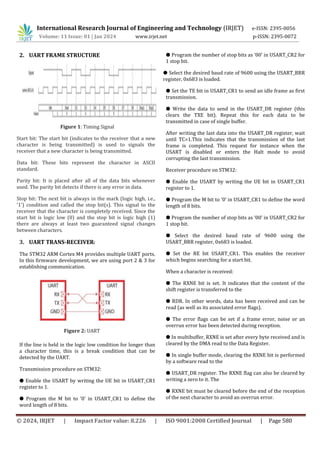
The pins are multiplexed with more than one operation, by
default all port act as input output pins. Therefore, when the
transmitter is disabled, the output pin returns to its I/O port
configuration. When the transmitter is enabled and nothing is
to be transmitted, the Tx pin is at high level. When a
transmission is taking place, a write instruction stores the
data in the data register and which is copied in the shift
register at the end of the current transmission [1]. When no
transmission is taking place, a write instruction places the
data directly in the shift register, the data transmission starts,
and the transmission bit is immediately set. After writing the
last data into the data register, it is mandatory to wait for
transmission completion bit to set before disabling the UART
or causing the microcontroller to enter the low-power mode.
During an UART reception, data shifts in least significant
bit first through the Rx pin. In this mode, the data register
consists of a buffer between the internal bus and the received
shift register. When a character is received, the receive
completion bit is set which indicates that the content of the
shift register is transferred to the receiver data register.
The data transmitted should be sampled at the
appropriate moment, otherwise there may be a data loss or
data may get erroneous. The transmitter and receiver must
be compatible on the baud rate to receive data accurately.
The different control registers are configured to set
appropriate baud rate and establish successful
communication which is also verified and validated using
status bits. The data word length is 8 bits with NRZ standard
format and also includes a parity bit for validation [2]. Data
registers available consists a buffer between the internal bus
and the transmit shift register.
International Research Journal of Engineering and Technology (IRJET) e-ISSN: 2395-0056
Volume: 11 Issue: 01 | Jan 2024 www.irjet.net p-ISSN: 2395-0072](https://image.slidesharecdn.com/irjet-v11i194-240214144118-c6709d76/85/Firmware-implementation-of-UART-using-Bare-metal-programming-1-320.jpg)


This document discusses the implementation of UART (Universal Asynchronous Receiver-Transmitter) communication using bare metal programming on an STM32 microcontroller. UART allows for asynchronous serial communication between devices. The implementation establishes communication between two UART ports on the microcontroller in a loopback configuration and displays the status on an LCD screen. It configures the UART registers to set the baud rate, data format, and handles transmission and reception in compliance with the UART protocol.