A Universal Asynchronous Receiver/Transmitter (UART) is a computer hardware device that translates data between parallel and serial forms, enabling serial communication. A UART takes bytes of data and transmits the individual bits sequentially. At the destination, another UART reassembles the bits into complete bytes. UARTs are commonly used with communication standards like RS-232 and protocols like EIA to enable serial communication between computers and peripheral devices.
![Universal asynchronous receiver/transmitter
From Wikipedia, the free encyclopedia
This article needs additional citations for verification. Please help improve
this article by adding citations to reliable sources. Unsourced material may
be challenged and removed. (November 2010)
A Universal Asynchronous Receiver/Transmitter, abbreviated UART /ˈjuˈɑ rt/, is a piece of computer
hardware that translates data between parallel and serial forms. UARTs are commonly used in conjunction
with communication standards such as EIA, RS-232, RS-422 or RS-485. The universal designation
indicates that the data format and transmission speeds are configurable. The electric signaling levels and
methods (such as differential signaling etc.) are handled by a driver circuit external to the UART.
A UART is usually an individual (or part of an) integrated circuit used for serial communications over a
computer or peripheral device serial port. UARTs are now commonly included in microcontrollers. A dual
UART, or DUART, combines two UARTs into a single chip. Many modern ICs now come with a UART that
can also communicate synchronously; these devices are calledUSARTs (universal
synchronous/asynchronous receiver/transmitter).
Contents
[hide]
1 Transmitting and receiving serial data
o 1.1 Character framing
o 1.2 Receiver
o 1.3 Transmitter
o 1.4 Application
2 Synchronous transmission
3 History
4 Structure
5 Special receiver conditions
o 5.1 Overrun error
o 5.2 Underrun error
o 5.3 Framing error
o 5.4 Parity error
o 5.5 Break condition
6 UART models
7 UART in modems
8 See also](https://image.slidesharecdn.com/uartwiki-130618143445-phpapp01/85/Uart-wiki-1-320.jpg)
![Universal asynchronous receiver/transmitter
From Wikipedia, the free encyclopedia
This article needs additional citations for verification. Please help improve
this article by adding citations to reliable sources. Unsourced material may
be challenged and removed. (November 2010)
A Universal Asynchronous Receiver/Transmitter, abbreviated UART /ˈjuˈɑ rt/, is a piece of computer
hardware that translates data between parallel and serial forms. UARTs are commonly used in conjunction
with communication standards such as EIA, RS-232, RS-422 or RS-485. The universal designation
indicates that the data format and transmission speeds are configurable. The electric signaling levels and
methods (such as differential signaling etc.) are handled by a driver circuit external to the UART.
A UART is usually an individual (or part of an) integrated circuit used for serial communications over a
computer or peripheral device serial port. UARTs are now commonly included in microcontrollers. A dual
UART, or DUART, combines two UARTs into a single chip. Many modern ICs now come with a UART that
can also communicate synchronously; these devices are calledUSARTs (universal
synchronous/asynchronous receiver/transmitter).
Contents
[hide]
1 Transmitting and receiving serial data
o 1.1 Character framing
o 1.2 Receiver
o 1.3 Transmitter
o 1.4 Application
2 Synchronous transmission
3 History
4 Structure
5 Special receiver conditions
o 5.1 Overrun error
o 5.2 Underrun error
o 5.3 Framing error
o 5.4 Parity error
o 5.5 Break condition
6 UART models
7 UART in modems
8 See also](https://image.slidesharecdn.com/uartwiki-130618143445-phpapp01/75/Uart-wiki-1-2048.jpg)
![9 References
10 External links
Transmitting and receiving serial data[edit]
See also: Asynchronous serial communication
The Universal Asynchronous Receiver/Transmitter (UART) takes bytes of data and transmits the individual
bits in a sequential fashion.[1]
At the destination, a second UART re-assembles the bits into complete bytes.
Each UART contains a shift register, which is the fundamental method of conversion between serial and
parallel forms. Serial transmission of digital information (bits) through a single wire or other medium is less
costly than parallel transmission through multiple wires.
The UART usually does not directly generate or receive the external signals used between different items
of equipment. Separate interface devices are used to convert the logic level signals of the UART to and
from the external signaling levels. External signals may be of many different forms. Examples of standards
for voltage signaling are RS-232, RS-422 and RS-485 from the EIA. Historically, current (in current loops)
was used in telegraph circuits. Some signaling schemes do not use electrical wires. Examples of such
are optical fiber, IrDA (infrared), and (wireless)Bluetooth in its Serial Port Profile (SPP). Some signaling
schemes use modulation of a carrier signal (with or without wires). Examples are modulation of audio
signals with phone line modems, RF modulation with data radios, and the DC-LIN for power line
communication.
Communication may be simplex (in one direction only, with no provision for the receiving device to send
information back to the transmitting device), full duplex (both devices send and receive at the same time)
or half duplex (devices take turns transmitting and receiving).
Character framing[edit]
The right-most (least significant) data bit is always transmitted first. If parity is present, the parity bit comes
after the data bits but before the stop bit(s).
Bit
number
1 2 3 4 5 6 7 8 9 10 11
Start bit 5–8 data bits Stop bit(s)
Start Data 0 Data 1 Data 2 Data 3 Data 4 Data 5 Data 6 Data 7 Stop
The idle, no data state is high-voltage, or powered. This is a historic legacy from telegraphy, in which the
line is held high to show that the line and transmitter are not damaged. Each character is sent as a logic
low start bit, a configurable number of data bits (usually 8, but users can choose 5 to 8 or 9 bits depending
on which UART is in use), an optional parity bit if the number of bits per character chosen is not 9 bits, and
one or more logic high stop bits.
The start bit signals the receiver that a new character is coming. The next five to nine bits, depending on
the code set employed, represent the character. If a parity bit is used, it would be placed after all of the
data bits. The next one or two bits are always in the mark (logic high, i.e., '1') condition and called the stop](https://image.slidesharecdn.com/uartwiki-130618143445-phpapp01/85/Uart-wiki-2-320.jpg)
![bit(s). They signal the receiver that the character is completed. Since the start bit is logic low (0) and the
stop bit is logic high (1) there are always at least two guaranteed signal changes between characters.
If the line is held in the logic low condition for longer than a character time, this is a break condition that can
be detected by the UART.
Receiver[edit]
All operations of the UART hardware are controlled by a clock signal which runs at a multiple of the data
rate, typically 8 times the bit rate. The receiver tests the state of the incoming signal on each clock pulse,
looking for the beginning of the start bit. If the apparent start bit lasts at least one-half of the bit time, it is
valid and signals the start of a new character. If not, it is considered a spurious pulse and is ignored. After
waiting a further bit time, the state of the line is again sampled and the resulting level clocked into a shift
register. After the required number of bit periods for the character length (5 to 8 bits, typically) have
elapsed, the contents of the shift register are made available (in parallel fashion) to the receiving system.
The UART will set a flag indicating new data is available, and may also generate a processor interrupt to
request that the host processor transfers the received data.
Communicating UARTs usually have no shared timing system apart from the communication signal.
Typically, UARTs resynchronize their internal clocks on each change of the data line that is not considered
a spurious pulse. Obtaining timing information in this manner, they reliably receive when the transmitter is
sending at a slightly different speed than it should. Simplistic UARTs do not do this, instead they
resynchronize on the falling edge of the start bit only, and then read the center of each expected data bit,
and this system works if the broadcast data rate is accurate enough to allow the stop bits to be sampled
reliably.
It is a standard feature for a UART to store the most recent character while receiving the next. This "double
buffering" gives a receiving computer an entire character transmission time to fetch a received character.
Many UARTs have a small first-in, first-out FIFO buffer memory between the receiver shift register and the
host system interface. This allows the host processor even more time to handle an interrupt from the UART
and prevents loss of received data at high rates.
Transmitter[edit]
Transmission operation is simpler since it is under the control of the transmitting system. As soon as data is
deposited in the shift register after completion of the previous character, the UART hardware generates a
start bit, shifts the required number of data bits out to the line, generates and appends the parity bit (if
used), and appends the stop bits. Since transmission of a single character may take a long time relative to
CPU speeds, the UART will maintain a flag showing busy status so that the host system does not deposit a
new character for transmission until the previous one has been completed; this may also be done with an
interrupt. Since full-duplex operation requires characters to be sent and received at the same time, UARTs
use two different shift registers for transmitted characters and received characters.
Application[edit]](https://image.slidesharecdn.com/uartwiki-130618143445-phpapp01/85/Uart-wiki-3-320.jpg)
![Transmitting and receiving UARTs must be set for the same bit speed, character length, parity, and stop
bits for proper operation. The receiving UART may detect some mismatched settings and set a "framing
error" flag bit for the host system; in exceptional cases the receiving UART will produce an erratic stream of
mutilated characters and transfer them to the host system.
Typical serial ports used with personal computers connected to modems use eight data bits, no parity, and
one stop bit; for this configuration the number of ASCII characters per second equals the bit rate divided by
10.
Some very low-cost home computers or embedded systems dispensed with a UART and used the CPU to
sample the state of an input port or directly manipulate an output port for data transmission. While very
CPU-intensive, since the CPU timing was critical, these schemes avoided the purchase of a UART chip.
The technique was known as a bit-banging serial port.
Synchronous transmission[edit]
USART chips have both synchronous and asynchronous modes. In synchronous transmission, the clock
data is recovered separately from the data stream and no start/stop bits are used. This improves the
efficiency of transmission on suitable channels since more of the bits sent are usable data and not
character framing. An asynchronous transmission sends no characters over the interconnection when the
transmitting device has nothing to send; but a synchronous interface must send "pad" characters to
maintain synchronization between the receiver and transmitter. The usual filler is the ASCII "SYN"
character. This may be done automatically by the transmitting device.
History[edit]
Some early telegraph schemes used variable-length pulses (as in Morse code) and rotating clockwork
mechanisms to transmit alphabetic characters. The first UART-like devices (with fixed-length pulses) were
rotating mechanical switches (commutators). Various character codes using 5, 6, 7, or 8 data bits became
common in teleprinters and later as computer peripherals. Gordon Bell designed the UART for
the PDP series of computers. The teletypewriter made an excellent general-purpose I/O device for a small
computer. To reduce costs, including wiring and back-plane costs, these computers also pioneered flow
control using XON and XOFF characters rather than hardware wires.
Western Digital made the first single-chip UART WD1402A around 1971; this was an early example of
a medium scale integrated circuit. Another popular chip was a SCN2651 from the Signetics 2650 family.
An example of an early 1980s UART was the National Semiconductor 8250. In the 1990s, newer UARTs
were developed with on-chip buffers. This allowed higher transmission speed without data loss and without
requiring such frequent attention from the computer. For example, the popular National
Semiconductor 16550 has a 16 byte FIFO, and spawned many variants, including the16C550, 16C650,
16C750, and 16C850.](https://image.slidesharecdn.com/uartwiki-130618143445-phpapp01/85/Uart-wiki-4-320.jpg)
![Depending on the manufacturer, different terms are used to identify devices that perform the UART
functions. Intel called their 8251 device a "Programmable Communication Interface". MOS
Technology 6551 was known under the name "Asynchronous Communications Interface Adapter" (ACIA).
The term "Serial Communications Interface" (SCI) was first used at Motorola around 1975 to refer to their
start-stop asynchronous serial interface device, which others were calling a UART. Zilog manufactured a
number of Serial Communication Controllers or SCCs.
Structure[edit]
A UART usually contains the following components:
a clock generator, usually a multiple of the bit rate to allow sampling in
the middle of a bit period.
input and output shift registers
transmit/receive control
read/write control logic
transmit/receive buffers (optional)
parallel data bus buffer (optional)
First-in, first-out (FIFO) buffer memory (optional)
Special receiver conditions[edit]
Overrun error[edit]
An "overrun error" occurs when the receiver cannot process the character that just came in before the next
one arrives. Various devices have different amounts of buffer space to hold received characters. The CPU
must service the UART in order to remove characters from the input buffer. If the CPU does not service the
UART quickly enough and the buffer becomes full, an Overrun Error will occur, and incoming characters
will be lost.
Underrun error[edit]
An "underrun error" occurs when the UART transmitter has completed sending a character and the transmit
buffer is empty. In asynchronous modes this is treated as an indication that no data remains to be
transmitted, rather than an error, since additional stop bits can be appended. This error indication is
commonly found in USARTs, since an underrun is more serious in synchronous systems.
Framing error[edit]
A "framing error" occurs when the designated "start" and "stop" bits are not found. As the "start" bit is used
to identify the beginning of an incoming character, it acts as a reference for the remaining bits. If the data
line is not in the expected state (hi/lo) when the "stop" bit is expected, a Framing Error will occur.
Parity error[edit]](https://image.slidesharecdn.com/uartwiki-130618143445-phpapp01/85/Uart-wiki-5-320.jpg)
![A Parity Error occurs when the parity of the number of 1 bits disagrees with that specified by the parity bit.
Use of a parity bit is optional, so this error will only occur if parity-checking has been enabled.
Break condition[edit]
A "break condition" occurs when the receiver input is at the "space" level for longer than some duration of
time, typically, for more than a character time. This is not necessarily an error, but appears to the receiver
as a character of all zero bits with a framing error.
Some equipment will deliberately transmit the "break" level for longer than a character as an out-of-
band signal. When signaling rates are mismatched, no meaningful characters can be sent, but a long
"break" signal can be a useful way to get the attention of a mismatched receiver to do something (such as
resetting itself). Unix-like systems can use the long "break" level as a request to change the signaling rate,
to support dial-in access at multiple signaling rates.
UART models[edit]
Model Description
EXAR
XR21V1410
Intersil 6402
CDP 1854
(RCA, now
Intersil)
Zilog Z8440
2000 kbit/s. Async, Bisync, SDLC, HDLC, X.25. CRC. 4-byte RX buffer. 2-byte TX
buffer. DMA.[2]
8250
Obsolete with 1-byte buffers. These UARTs' maximmum standard serial port speed is 9600
bits per second if the operating system has a 1 millisecond interrupt latency.
8251
Z8530/85C30
Motorola 6850](https://image.slidesharecdn.com/uartwiki-130618143445-phpapp01/85/Uart-wiki-6-320.jpg)
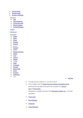
![6522
6551
Rockwell
65C52
16450
16550
This UART's FIFO was broken, so it can only work as slowly as the 16450 UART. The
16550A and later versions fix this bug.
16550A This UART has 16-byte FIFO buffers. Its receive interrupt trigger levels can be set to 1, 4, 8,
or 14 characters. Its maximum standard serial port speed if the operating system has a 1
milisecond interrupt latency is 115.2 kbit/s. Operating systems with lower interrupt latencies
could handle higher baud rates like 230.4 kbit/s or 460.8 kbit/s. This chip can provide signals
to facilitate a third party DMA controller perform DMA transfers to and from the UART. This
was known as DMA mode because it was meant to be coupled with a DMA controller in this
mode to perform the transfers on behalf of the CPU.[3]
It was introduced by National
Semiconductor, which has been sold to Texas Instruments. National Semiconductor claimed
that this UART could physically run at up to 1.5 Mbps.
16C552
16650
This UART was introduced by Startech Semiconductor which is now owned by Exar
Corporation and is not related to Startech.com. Early versions had a broken FIFO buffer and
therefore only could work as slowly as a 16450.[4]
Versions of this UART that were not broken
had 32-character FIFO buffers and could function at standard serial port speeds up to 230.4
kbit/s if the operating system has a 1 millisecond interrupt latency. Current versions of this
UART by Exar claim to be able to physically handle up to 1.5 Mbps. This UART introduces
the Auto-RTS and Auto-CTS features in which the RTS# signal is controlled by the UART to
signal the external device to stop transmitting when the UART's buffer is full to or beyond a
user-set trigger point and to stop transmitting to the device when the device drives the CTS#
signal high (logic 0).
16750
64-byte buffers. This UART can handle a maximum standard serial port speed of 460.8 kbps if
the maximum interrupt latency is 1 millisecond. This UART was introduced by Texas
Instruments. TI claims that early models can run up to 1 Mbps physically, and later models can
run up to 5 Mbps physically.
16850 128-byte buffers. This UART can handle a maximum standard serial port speed of 921.6 kbps
if the maximum interrupt latency is 1 millisecond. This UART was introduced by Exar
Corporation. Exar claims that early models can run up to 1.5 Mbps physically, and later
models can run up to 6.25 Mbps physically.16C850](https://image.slidesharecdn.com/uartwiki-130618143445-phpapp01/85/Uart-wiki-7-320.jpg)
![16950 128-byte buffers. This UART can handle a maximum standard serial port speed of 921.6 kbps
if the maximum interrupt latency is 1 millisecond. This UART supports 9-bit characters in
addition to the 5-8 bit characters other UARTs support. This was introduced by Oxford
Semiconductor, which is now owned by PLX Technology. Oxford/PLX claims that this UART
can run up to 15 Mbps physically. PCI Express variants by Oxford/PLX feed the UART's
DMA mode signals that were defined originally in the 16C550 to a first-party DMA engine in
the same chip that automatically move data to and from the serial port buffers without
requiring the CPU to do most of the work of moving the data in and out of the UART if it is
configured to do so.
16C950
16954 Quad port version of the 16950/16C950. 128-byte buffers per port. This UART can handle a
maximum standard serial port speed of 921.6 kbps if the maximum interrupt latency is 1
millisecond. This UART supports 9-bit characters in addition to the 5-8 bit characters other
UARTs support. This was introduced by Oxford Semiconductor, which is now owned by PLX
Technology. Oxford/PLX claims that this UART can run up to 15 Mbps physically. PCI
Express variants by Oxford/PLX feed the UART's DMA mode signals that were defined
originally in the 16C550 to a first-party DMA engine in the same chip that automatically move
data to and from the serial port buffers without requiring the CPU to do most of the work of
moving the data in and out of the UART if it is configured to do so.
16C954
Z85230
Synchronous/Asynchronous modes, 2 ports, DMA. 4-byte buffer to send, 8-byte buffer to
receive per channel. SDLC/HDLC modes. 5 Mbits/sec in synchronous mode.
Hayes ESP 1 kB buffers, 921.6 kbit/s, 8-ports.[5]
UART in modems[edit]
Modems for personal computers that plug into a motherboard slot must also include the UART function on
the card. The original 8250 UART chip shipped with the IBM personal computer had a one character buffer
for the receiver and the transmitter each, which meant that communications software performed poorly at
speeds above 9600 bits/second, especially if operating under a multitasking system or if handling interrupts
from disk controllers. High-speed modems used UARTs that were compatible with the original chip but
which included additional FIFO buffers, giving software additional time to respond to incoming data.
A look at the performance requirements at high bit rates shows why the 16, 32, 64 or 128 byte FIFO is a
necessity. The Microsoft specification for a DOS system requires that interrupts not be disabled for more
than 1 millisecond at a time. Some hard disk drives and video controllers violate this specification. 9600
bit/s will deliver a character approximately every millisecond, so a 1 byte FIFO should be sufficient at this
rate on a DOS system which meets the maximum interrupt disable timing. Rates above this may receive a
new character before the old one has been fetched, and thus the old character will be lost. This is referred
to as an overrun error and results in one or more lost characters.
A 16 byte FIFO allows up to 16 characters to be received before the computer has to service the interrupt.
This increases the maximum bit rate the computer can process reliably from 9600 to 153,000 bit/s if it has a
1 millisecond interrupt dead time. A 32 byte FIFO increases the maximum rate to over 300,000 bit/s. A](https://image.slidesharecdn.com/uartwiki-130618143445-phpapp01/85/Uart-wiki-8-320.jpg)
![second benefit to having a FIFO is that the computer only has to service about 8 to 12% as many
interrupts, allowing more CPU time for updating the screen, or doing other chores. Thus the computer's
responses will improve as well.
See also[edit]
Baud
bit rate
Modem
Morse code
Serial communication
Serial port
USB
References[edit]
1. ^ Adam Osborne, An Introduction to Microcomputers Volume 1: Basic
Concepts, Osborne-McGraw Hill Berkeley California USA, 1980 ISBN
0-931988-34-9 pp. 116-126
2. ^ "Zilog Product specification Z8440/1/2/4, Z84C40/1/2/3/4. Serial
input/output controller". 090529 zilog.com
3. ^ "FAQ: The 16550A UART & TurboCom drivers 1994". 090529
cs.utk.edu
4. ^ T'so, Theodore Y. (January 23, 1999). "Re: Serial communication
with the 16650". The Mail Archive. Retrieved June 2, 2013.
5. ^ bill.herrin.us - Hayes ESP 8-port Enhanced Serial Port Manual,
2004-03-02
External links[edit]
A tutorial on the RS-232 standard, describing the definition of mark,
space and their relationship with negative and positive voltages
Freebsd Tutorials, includes standard signal definitions, history of UART
ICs, and pinout for commonly used DB25 connector.
UART Tutorial for Robotics, contains many practical examples.
UART transceiver over powerline, allows multiplex UART networking
over the powerline.
[hide]
V](https://image.slidesharecdn.com/uartwiki-130618143445-phpapp01/85/Uart-wiki-9-320.jpg)