Downloaded 1,932 times


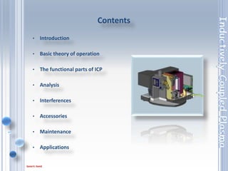

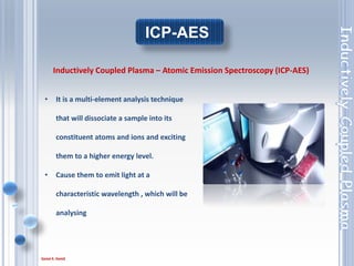
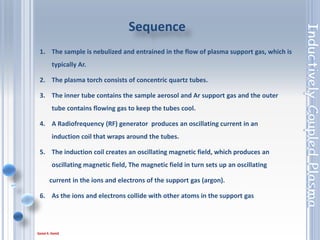
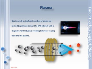
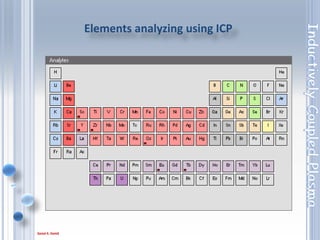
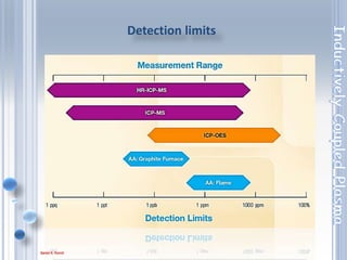
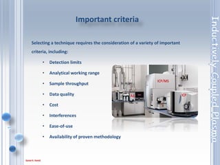


This document outlines the principles and components of Inductively Coupled Plasma - Atomic Emission Spectroscopy (ICP-AES), a multi-element analysis technique that dissociates samples into their constituent atoms and ions for analysis. It covers the operational mechanics, including the plasma generation, sample introduction, and optical detection systems, as well as important considerations for technique selection based on detection limits, cost, and sample throughput. The document also emphasizes proper laboratory conditions and sample preparation to ensure accurate and efficient analysis.


