1. The document reports on a student project studying the frequency of a Wien bridge oscillator.
2. It introduces the Wien bridge oscillator and how it produces continuous oscillations using an RC feedback network and amplifier.
3. The students analyze the frequency of their Wien bridge oscillator circuit experimentally and find that frequencies above 1MHz cannot be achieved due to limitations of the op-amp used.
Content
Introduction
Wienbridge oscillator
Basic of wien bridge oscillator
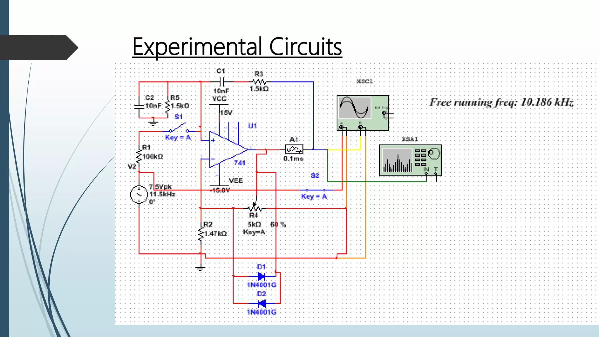
Experimental circuit
Result of wien bridge oscillator
Frequency analysis
Observation
Delay circuit
Future work
conclusion
3.
INTRODUCTION
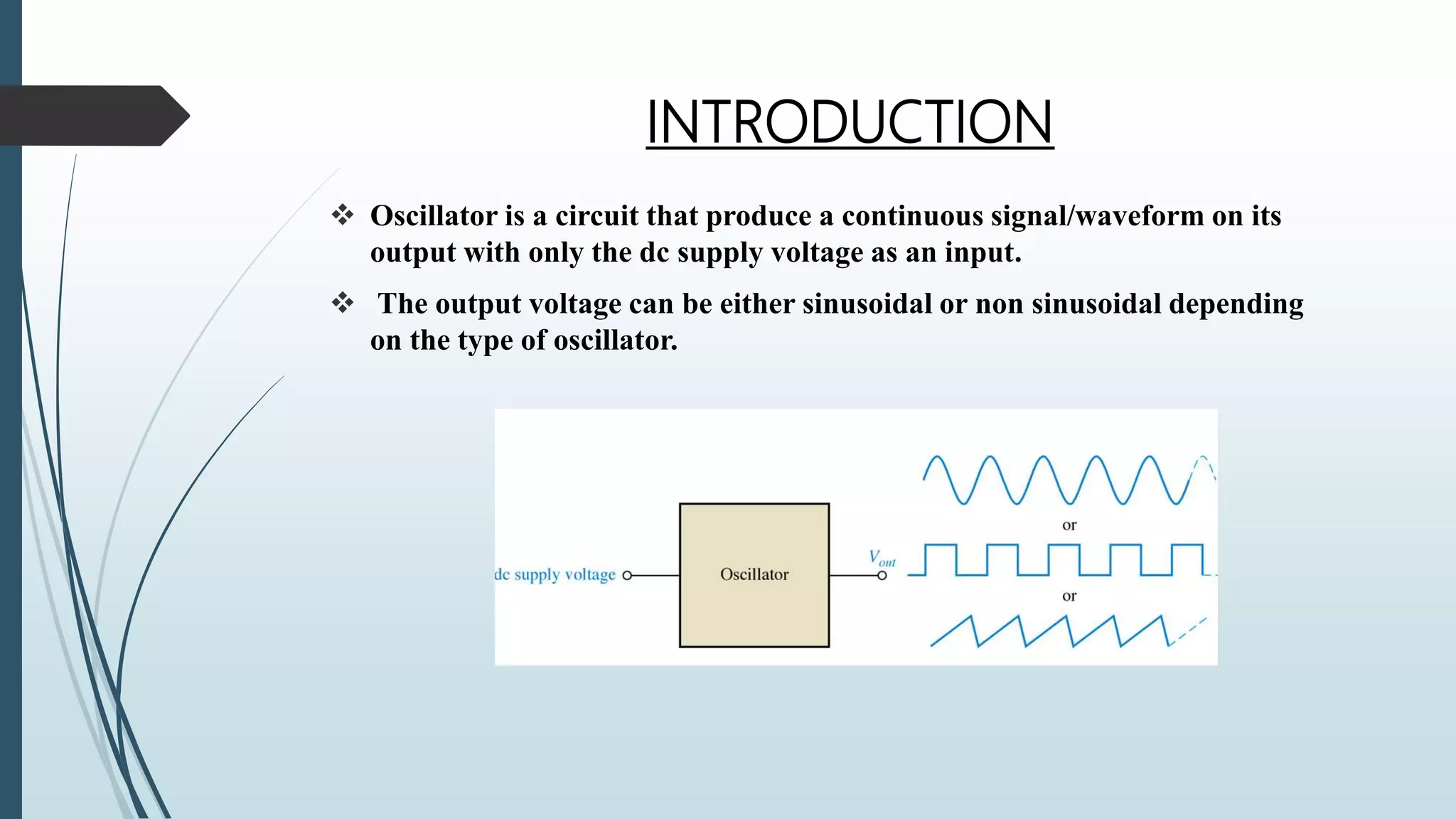
Oscillator isa circuit that produce a continuous signal/waveform on its
output with only the dc supply voltage as an input.
The output voltage can be either sinusoidal or non sinusoidal depending
on the type of oscillator.
4.
Wien Bridge Oscillator
With no input signal a Wien Bridge Oscillator produces continuous output oscillations.
The Wien Bridge Oscillator can produce a large range of frequencies.
The Voltage gain of the amplifier must be greater than 3.
The RC network can be used with a non-inverting amplifier.
Some method of stabilizing the amplitude of the oscillations must be provided. If the
voltage gain of the amplifier is too small the desired oscillation will decay and stop. If it
is too large the output will saturate to the value of the supply rails and distort.
With amplitude stabilization in the form of feedback diodes, oscillations from the wien
bridge oscillator can continue indefinitely.
5.
Basics About theWien-Bridge
Uses two RC networks
connected to the
positive terminal to form
a frequency selective
feedback network
Causes Oscillations to
Occur
6.
Condition to startthe oscillation
Oscillator circuit must satisfy the following two conditions known as
Barkhausen conditions:
i. The first condition is that the magnitude of the loop gain (Aβ) = 1
A = Amplifier gain and β = Feedback gain.
ii. The second condition is that the phase shift around the loop must be 360°
or 0°.
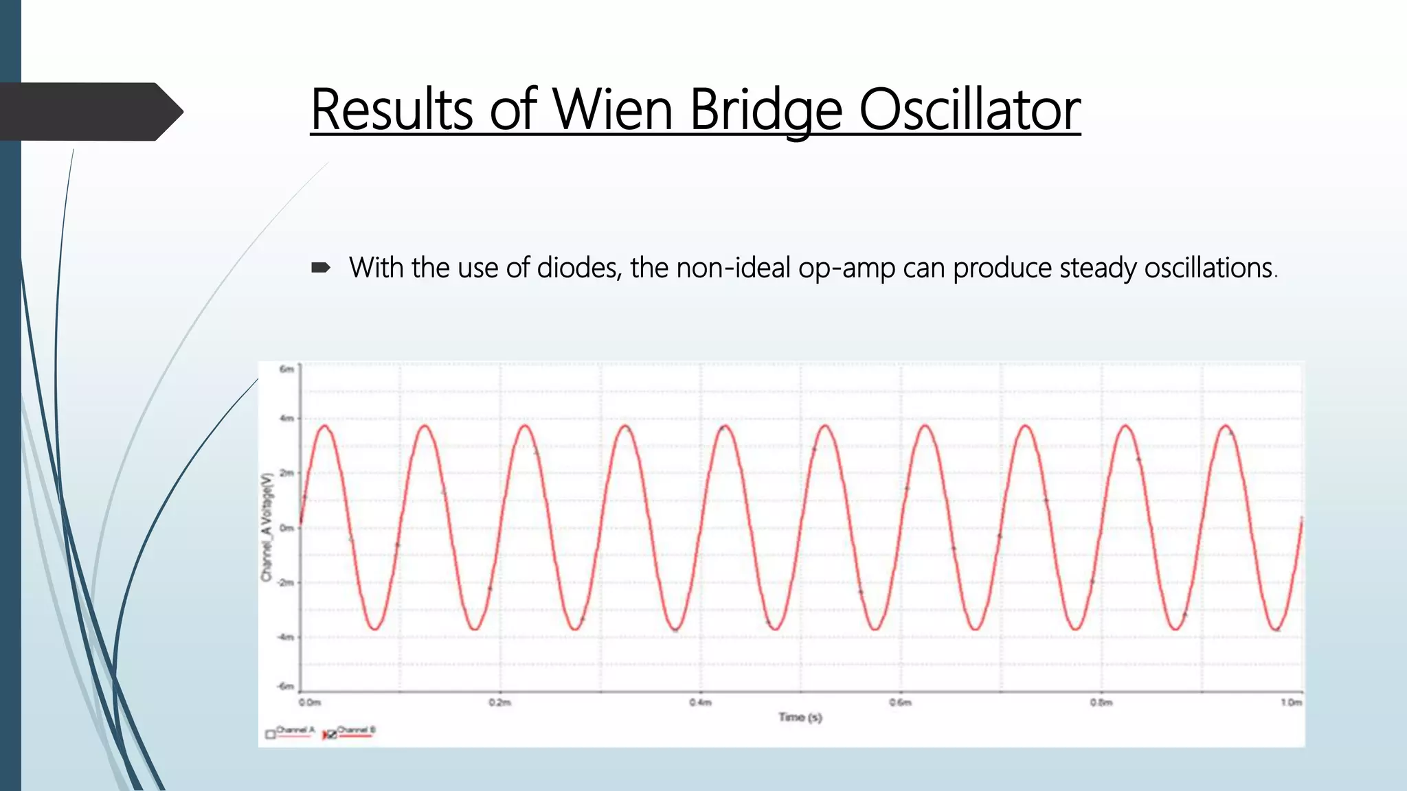
Results of WienBridge Oscillator
With the use of diodes, the non-ideal op-amp can produce steady oscillations.
9.
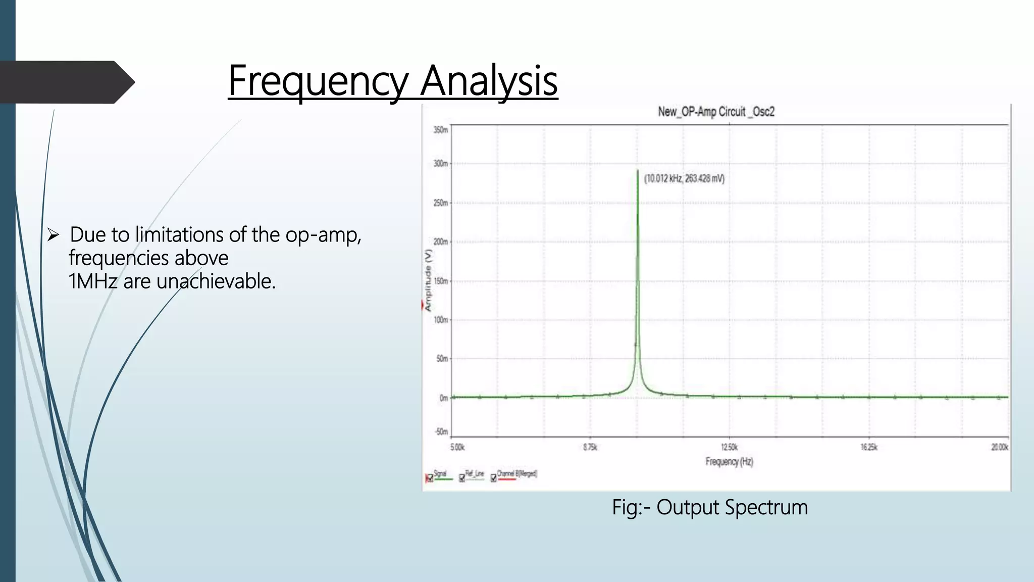
Frequency Analysis
Dueto limitations of the op-amp,
frequencies above
1MHz are unachievable.
Fig:- Output Spectrum
10.
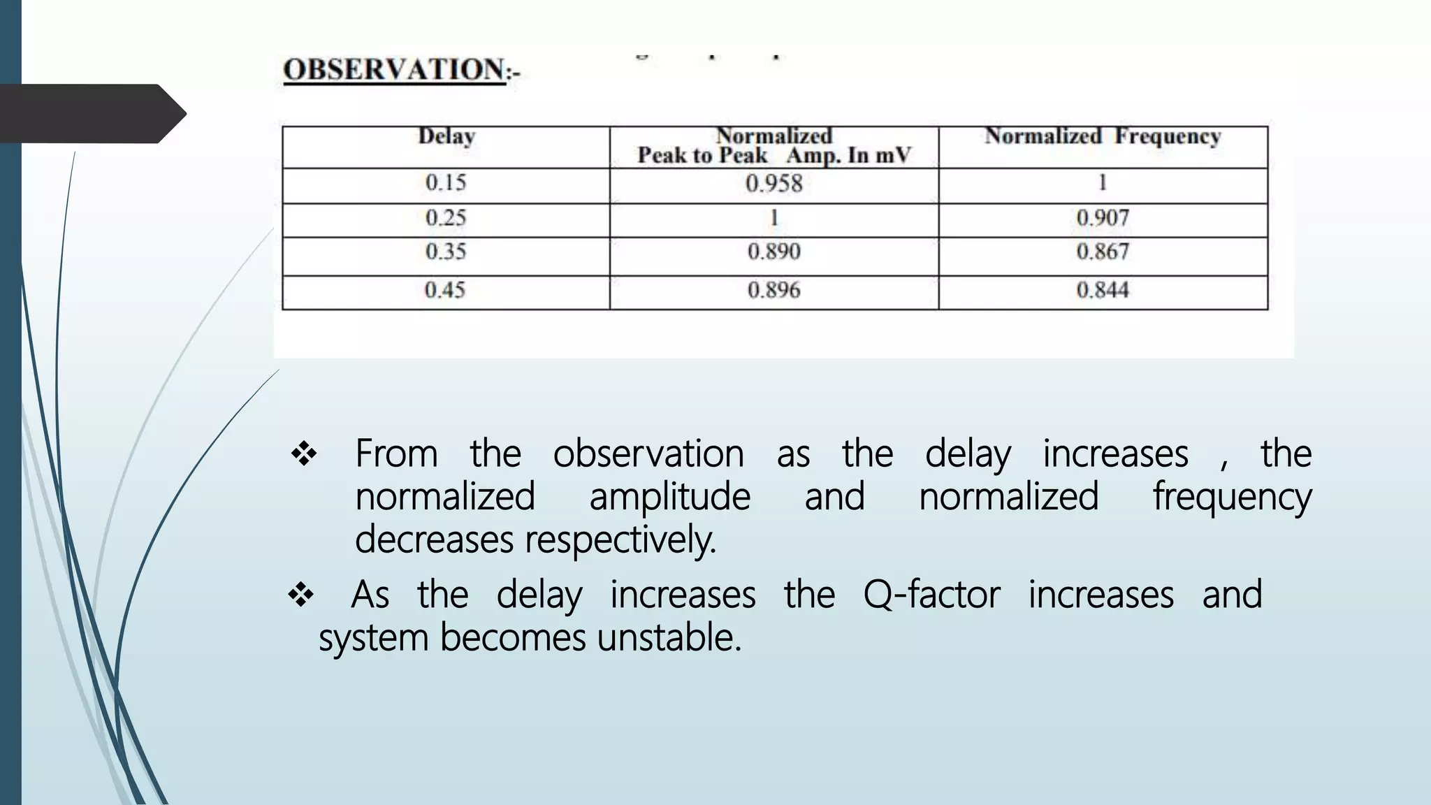
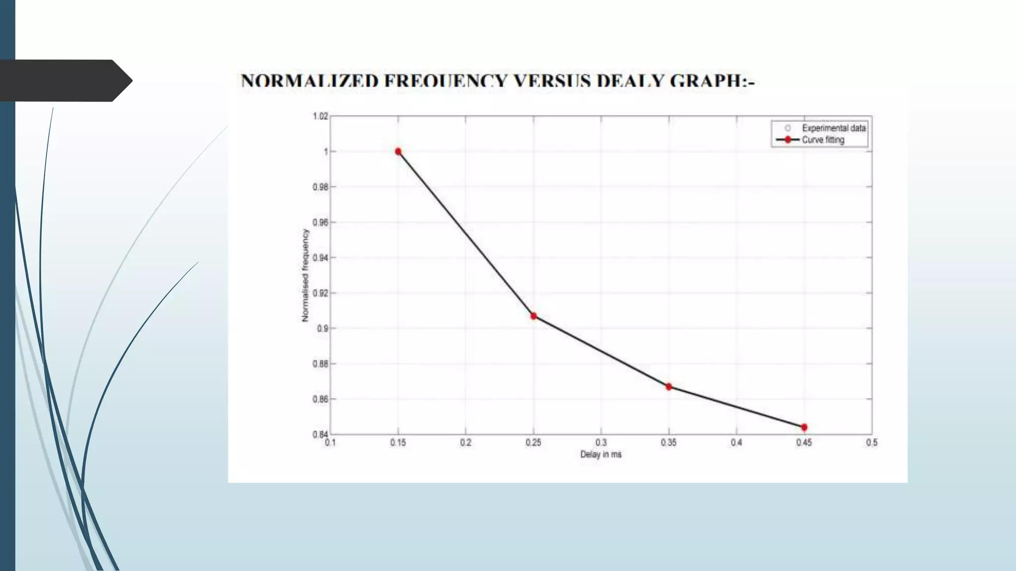
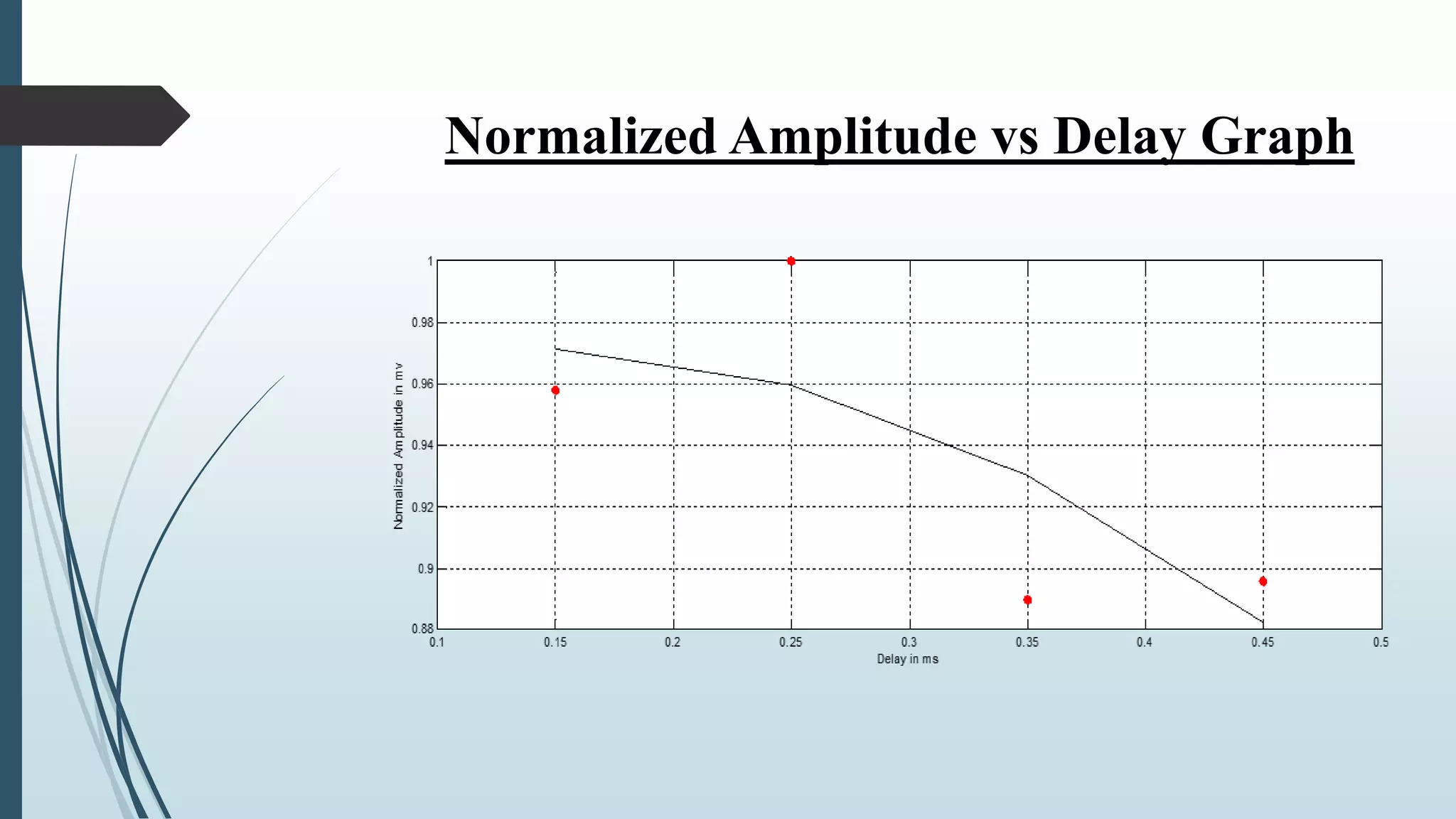
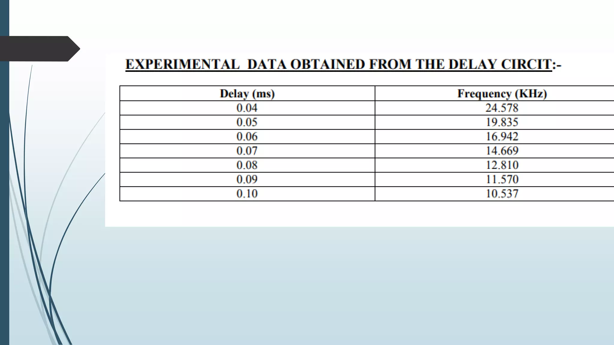
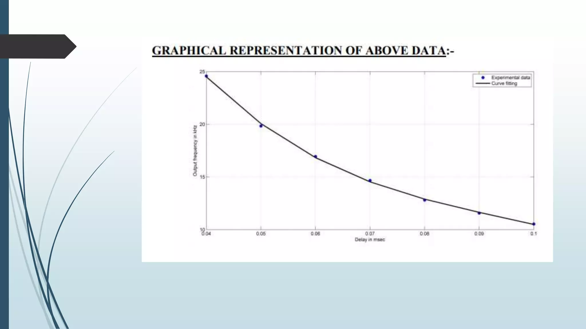
From theobservation as the delay increases , the
normalized amplitude and normalized frequency
decreases respectively.
As the delay increases the Q-factor increases and
system becomes unstable.
Delay circuit
Thisdevice is used to delay the signal as seen on the input. It can be configured
to exhibit transmission line style delay, or Transport Delay, using the delay type
parameter.
The delay circuit considerably changes operation of the op-Amp.
Future work
Delayis realized by actual circuit followed by similar studies.
Hardware realization of proposed circuit will be studied.
A theoretical analysis will be developed.
Synchronization issues of this wien bridge oscillator will be studied.
20.
Conclusions
Various aspectsof the behavior of “Frequency Entrainment in a
wien bridge Oscillator ” are studied.
Analyzing of frequency entrainment in a wien bridge Oscillator.
Due to limitation of op-amp frequencies above 1MHz cannot be
achieved.
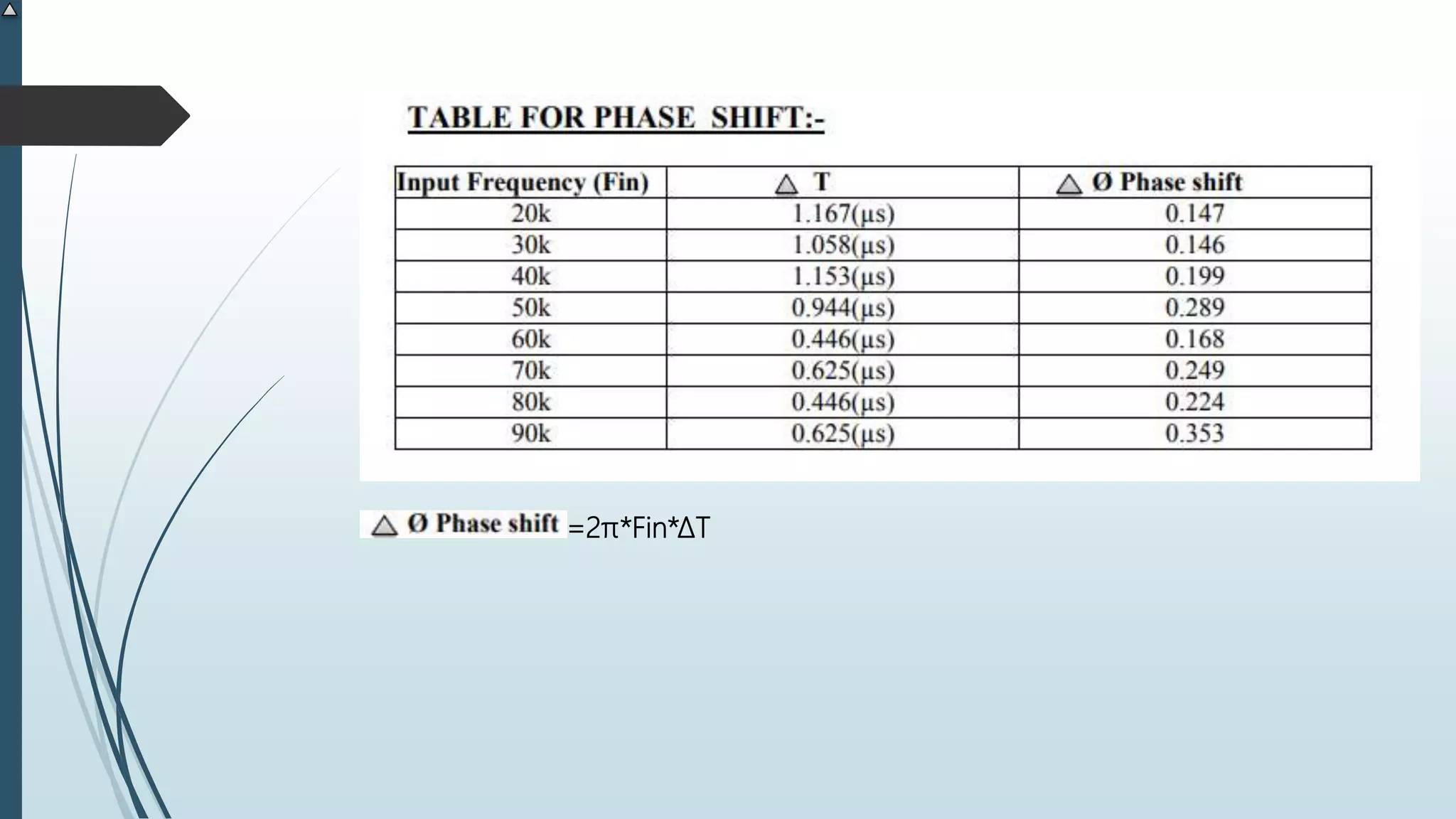
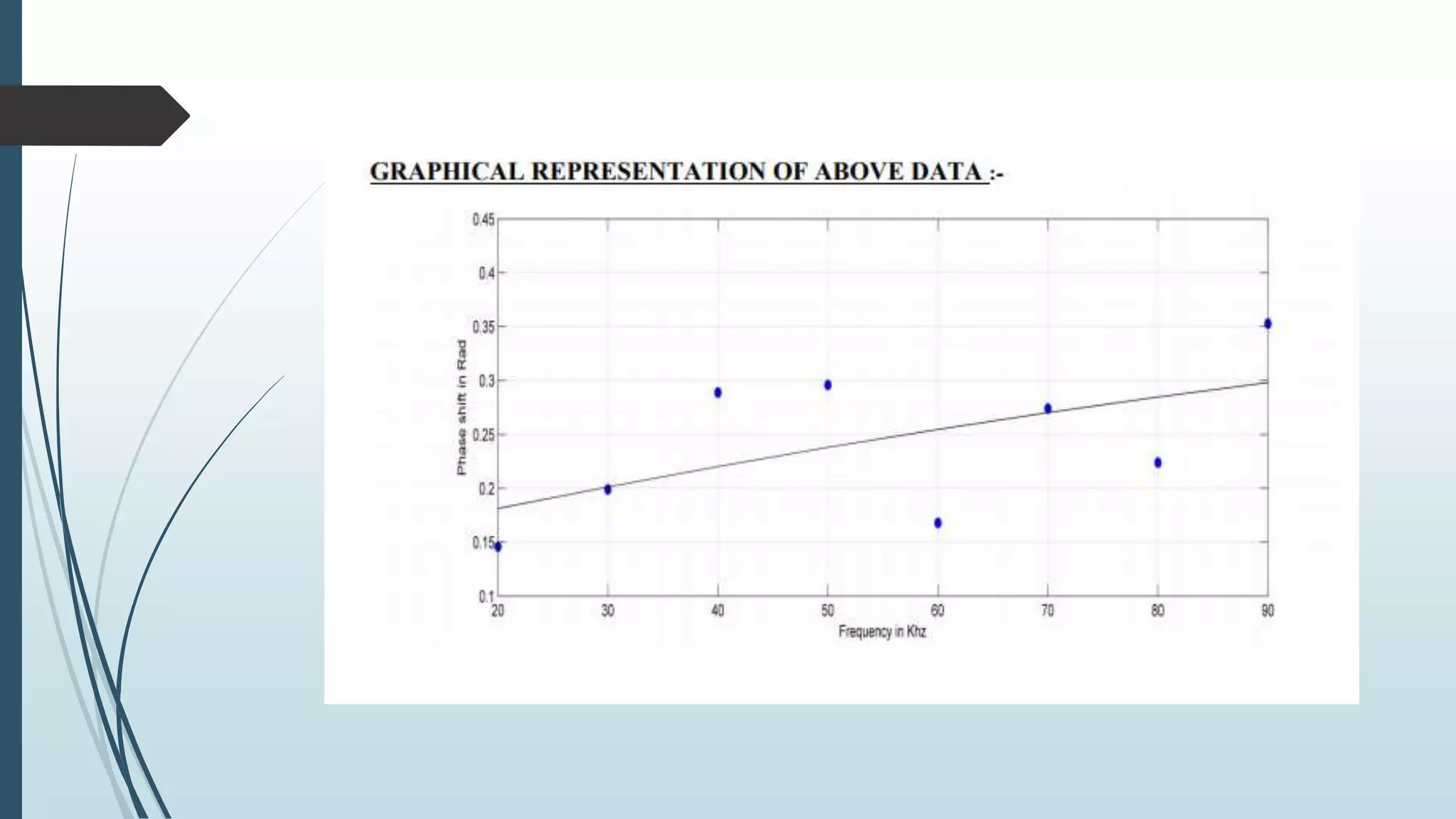
There is no phase shift.