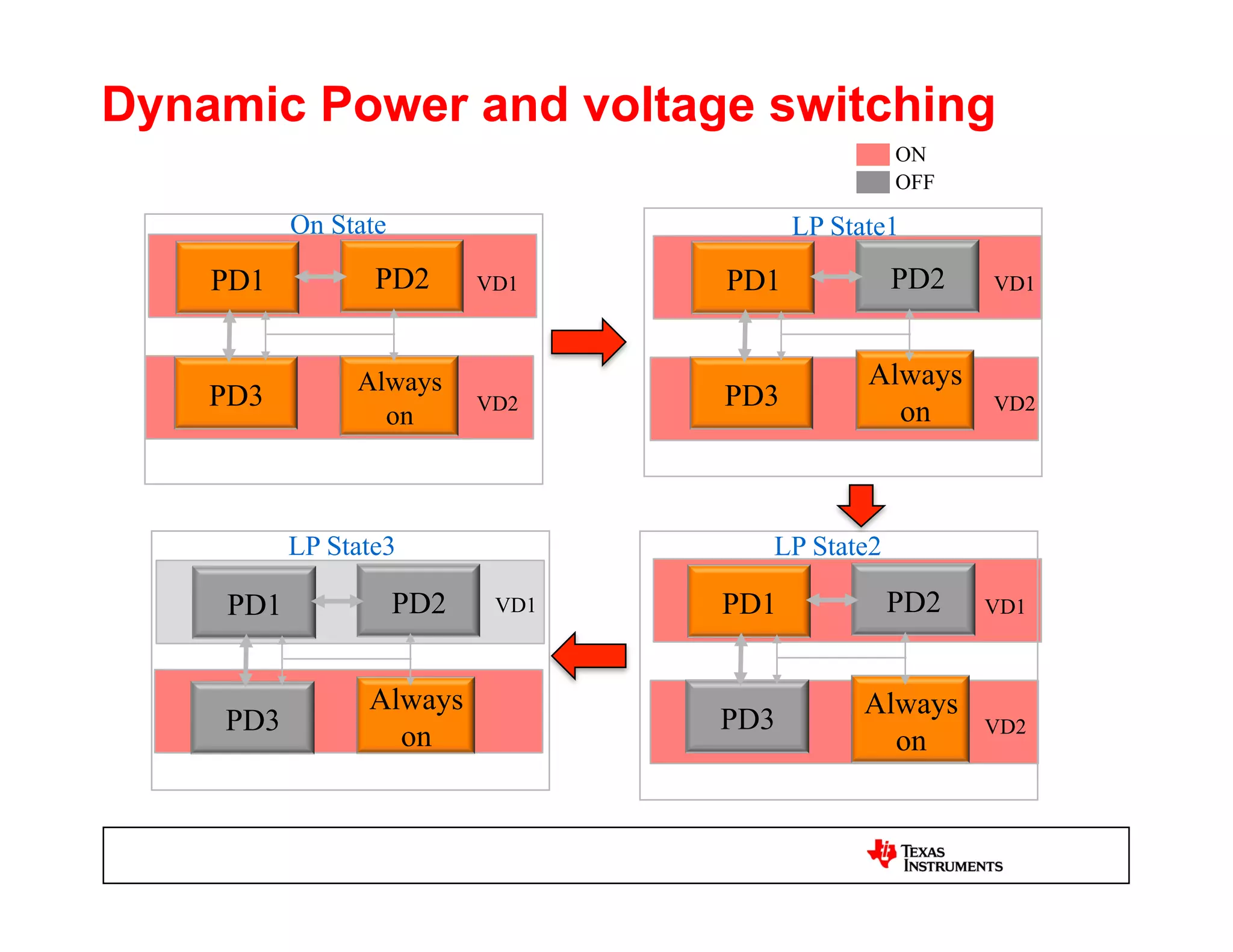
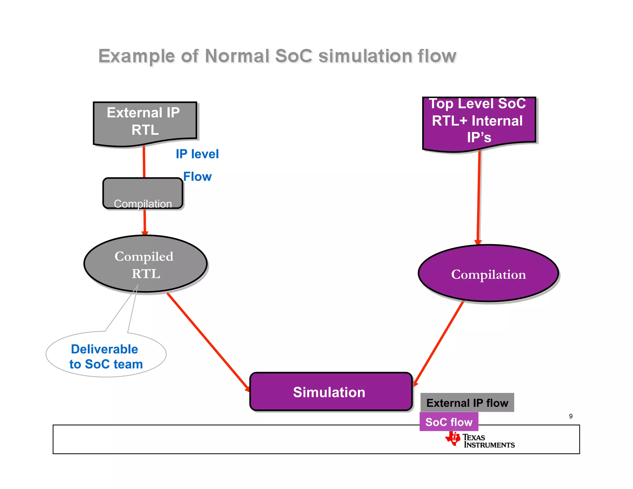
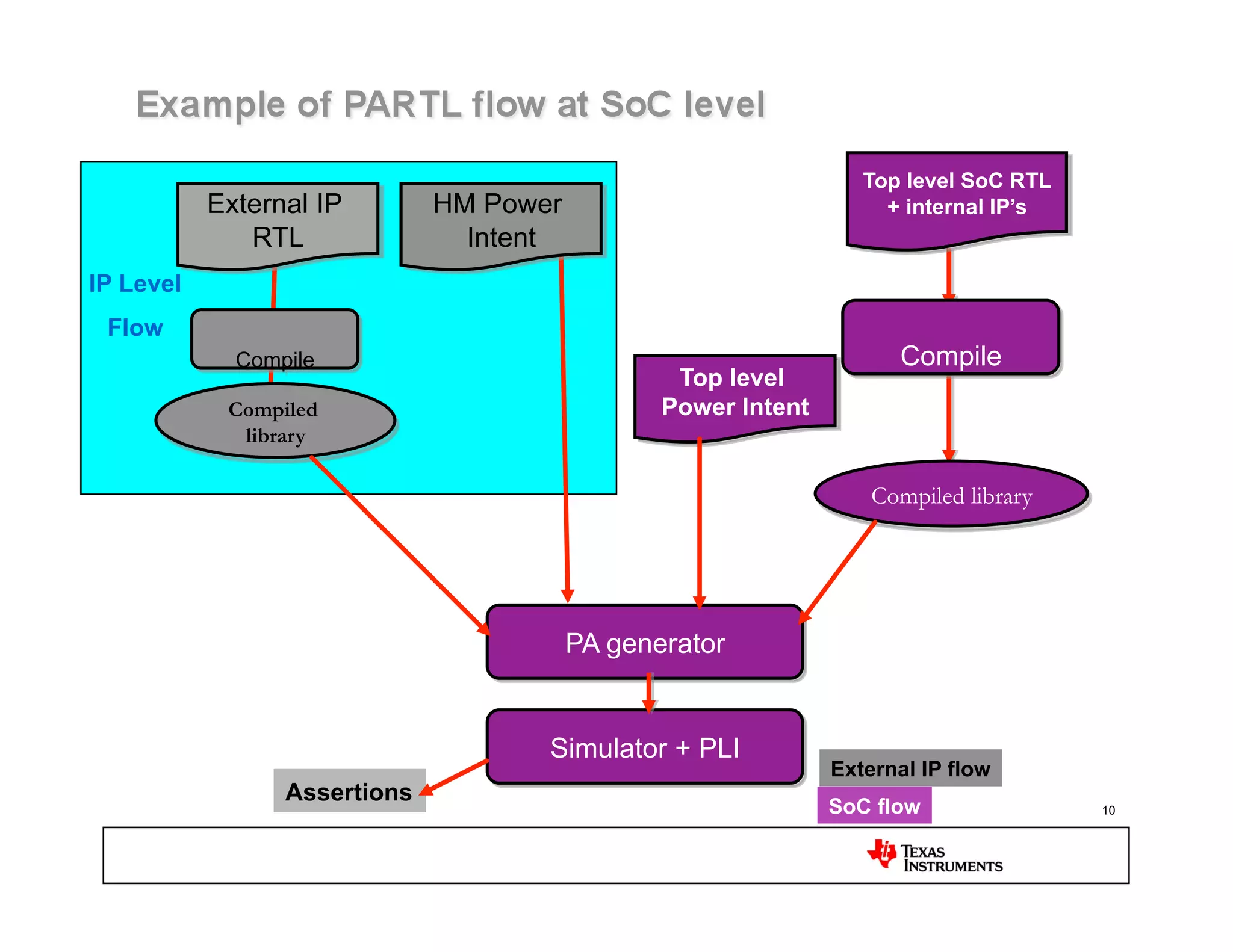
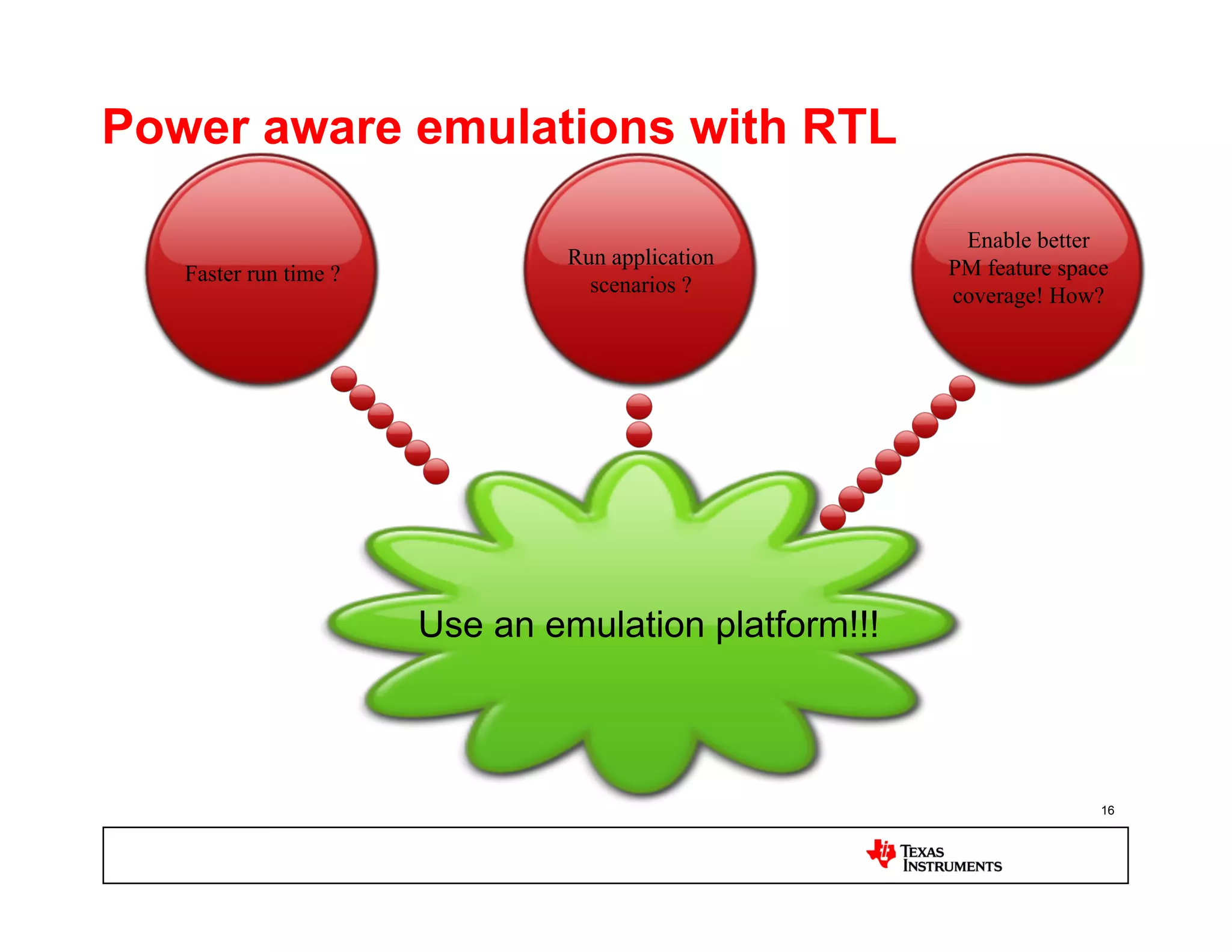
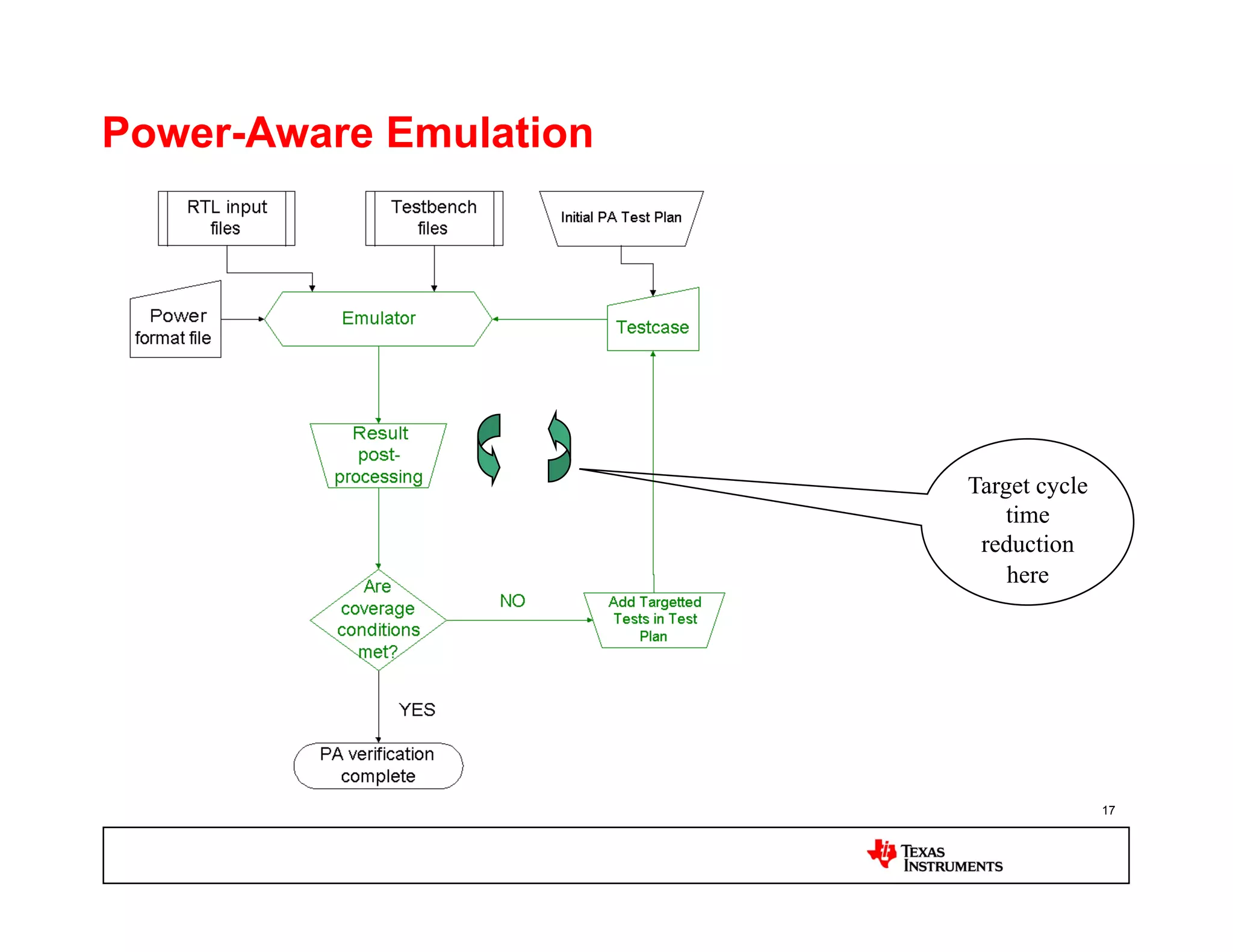
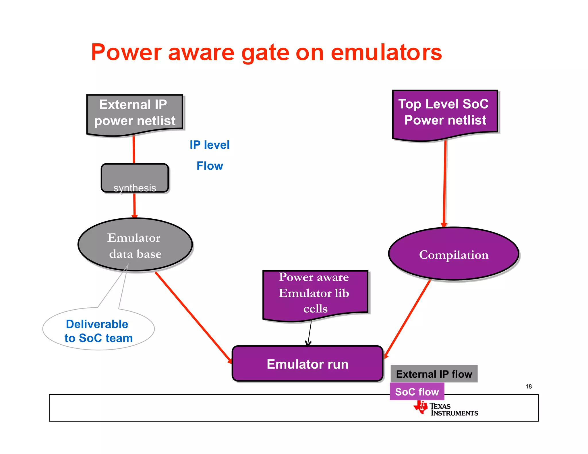
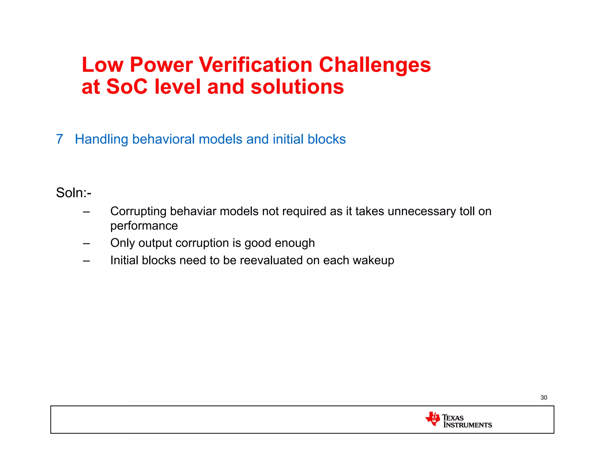
Approaches for Power
Management verification of SoC
  having dynamic power and
      voltage switching

        Prabhu Bhairi
      Texas Instruments

                                 1
Agenda
•  Overview of low power design
•  Why low power verification?

•  Limitation of traditional simulators.
•  Tools and flows at various stages of design cycle
   –  Flow details
   –  Pros’ con’s

•  Conclusion


                                                       2
Typical Low Power Design Desc.
•  Design Size > 20 Million gates
•  Multiple Voltage Domains and Power Domains
•  Many Always ON Paths
•  Lots of Power Switches, Isolations and Level Shifters and Always On buffers
•  Many Retention Flops
•  Power Management :
   –  Shutdown/Sleep: Voltage Domains and Power Domains
   –  Retention Schemes: Multiple retention flops

•  IP Intensive
   –  More than 100 IP’s
Dynamic Power and voltage switching
                                                ON
                                                OFF

          On State                      LP State1
    PD1          PD2       VD1    PD1           PD2    VD1


               Always                         Always
    PD3                    VD2    PD3                  VD2
                 on                             on


          LP State3                 LP State2

    PD1              PD2    VD1   PD1           PD2    VD1


                Always                        Always
    PD3                           PD3                  VD2
                  on                            on
Limitations of Traditional Simulators

•  Limitations
  –  There is no mechanism to partition design into multiple voltages and
     domains.
  –  Traditional simulators insensitive to power states of the device.
  –  Simulator engines does not recognize
         1.  Voltage changes.

         2.  Retention behavior of logic/memory


                                                                       5
What is power aware Simulation?
•  What is Power Aware Simulation ?
  –  Mimicking the power down/wakeup behavior at RTL/Gate level simulation.


•  Why is Power Aware Simulation needed ?
  –  Today’s complex SoC designs have considerable logic implemented for
     Power Management.
  –  Most of the PM logic can be implemented at RTL/Gate level.
  –  Important to find the critical bugs at early stages in the design cycle.
Approaches of Low power verification


1.  ynamic/simulator based verification
  D
2.  tatic/Structural Verification
  S


                                          7
Dynamic/simulator based verification approaches


1.  Simulator platforms
  –  RTL level(PARTL) : Power Aware RTL simulations-UPF/PCF/CPF
  –  Gate Level(PAGLS): Power Aware gate level simulations


2.  Emulator platform
  –  RTL Level : Power aware verification UPF/PCF/CPF based
  –  Gate Level: Power aware gate on accelerator platforms (Zero delay)


                                                                      8
Top Level SoC
     External IP
                                            RTL+ Internal
        RTL
                                                 IP’s
                    IP level
                     Flow

      Compilation


      Compiled
        RTL                                     Compilation


Deliverable
to SoC team

                               Simulation
                                            External IP flow
                                                               9
                                            SoC flow
Top level SoC RTL
           External IP        HM Power                              + internal IP’s
              RTL               Intent
IP Level
 Flow
             Compile                                                 Compile
                                                 Top level
            Compiled                            Power Intent
             library

                                                                   Compiled library


                                         PA generator


                                     Simulator + PLI
                                                               External IP flow
                 Assertions
                                                               SoC flow               10
Requirement of PARTL tools for SoC
 1.  Standard, inheritable and reusable (across all phases of the design cycle)
     power constraint specification
 2.  The constructs to have robust power intent specification
 3.  Handling Multi Vendor IPs (simulator specific Compiled RTL) with in-house
     logic in mixed HDL mode.
 4.  The Multiple Retention scheme, schemes could be vendor specific.
 5.  Low coverage at SoC level, cannot cover every flip flop and every signal by
     SoC level self checking scenario simulation.
        1.  Support of assertions
 6.  Extract the info about Retention flops, Latches, always on signals etc from
     RTL using the tool
 7.  Handling behavioral models.


                                                                               11
Pro’s and Con’s of PARTL
 •  Pro’s.
    –  Highlight issues very early in design cycle- Before RTL freeze.
    –  Easy to debug compared to other platforms.
    –  Run times are better than PAGLS


 •  Con’s
    –  No mechanism to validate the PCF files.
    –  Run time 2 to 3x slower than normal RTL simulation
    –  Tools are not very robust yet.


                                                                         12
What is power aware Gate

•  What is Power Aware gate?
   – It is a netlist with power switches and cells with power
     pins


•  Why is Power Aware gate?
   – Lot of power management features will be implemented
     by BE tools .
   – This netlist has all the switches and power connection so
     can catch any potential issue in power feature
     implementation
External IP                              Top Level SoC
    power Netlist                              Power Netlist
                    IP level
                     Flow

        Compile


                               Power aware
                               modeled cell
      Compiled                   libraries        Compilation
       library


Deliverable
to SoC team

                               Simulation
                                              External IP flow
                                                                 14
                                              SoC flow
Pro’s and Con’s of PAGLS
 •  Pro’s.
    –  Very close to final design hence best candidate to catch issues.
    –  Will catch any issue in BE implementations and power constraint file issues
    –  No Power constraint creation effort


 •  Con’s
    –  Run time and memory foot print 4 to 5x slower compared to PARTL
        •  Netlist is ~2 times bigger than normal netlist
    –  Very late in the design cycle.
    –  Debugging is very difficult.
    –  Developing the power aware library models is effort intensive.


                                                                               15
Power aware emulations with RTL

                                                       Enable better
                                Run application       PM feature space
   Faster run time ?              scenarios ?         coverage! How?


                       Use an emulation platform!!!


                                                                     16
Power-Aware Emulation


                        Target cycle
                            time
                         reduction
                            here


                                       17
External IP                               Top Level SoC
    power netlist                               Power netlist
                    IP level
                     Flow
       synthesis


      Emulator
      data base                                    Compilation
                                Power aware
                                Emulator lib
                                   cells
Deliverable
to SoC team

                               Emulator run
                                               External IP flow
                                                                  18
                                               SoC flow
Advantages
•  Randomized values may create a worst case scenario compared to “x” in
   simulations
•  Inherently faster platform.

•  System level use-cases for PA features can be planned and executed faster.
•  Enables us to do full coverage due to the speed the platform offers.


Limitations
•  There is no real “x” hence few fails may be masked

•  Many features not yet fully supported on production version in Emulations
   platforms

•  Debugging is tedious
•  Vulnerable to power constraints issues like PARTL if Emulation RTL flow is
   used
                                                                                19
Static/Structure verification


1.  Lint tools to verify PM connectivity
2.  Static low power verification on power netlist

3.  STA based static checks


                                                     20
Conclusion

•  Low power requirements have undoubtedly exposed a new challenge in
   DV/EDA community.
•  Lot of flows and EDA support already exist.
   –  Each of them have there own benefit and limitations

•  Given all this Silicon still remains the best platform for low power
   verification,
•  Pre SI DV: we just do not have a perfect solution today because of
   enormous complexity in the design. we should continue focus on
   improvement on flows and tools.
•  Simulation speed with low power enabled worsens even more.


                                                                          21
BACK UP


          22
Key words in low power implementation
•  Power domain
•  Voltage domain
•  Isolation cell
   –  Tie cell, ISO latch

•  Level shifter

•  Retention flip/flop, latch
•  Retention memory

•  Power switch
•  Wakeups
•  Always on logics/domains
•  IO iso/wakeup
                                        23
Low Power Verification Challenges at
SoC level and solutions

1.    Standard, inheritable and reusable (across all phases of the design cycle)
      power constraint specification


Soln:-
      –    Supports the standard power specification format (like UPF)
      –    If any legacy power intent is specified for an IP
           •    Ex: APF->UPF, PCF->UPF conversion is seamless to user.


                                                                                   24
Low Power Verification Challenges
    at SoC level and solutions

2   Support of constructs to have robust power intent specification.


Soln:-
    –    Support for wild character
         •    Ex *iso_cel* for specifying always on signals
    –    Support of expressions for power control signals
         •    Ex: A xor B for shutdown.
    –    Supports specifying the source, destination and cell kind of constructs for always
         on path tracing.


                                                                                          25
Low Power Verification Challenges
    at SoC level and solutions

3 Handling Multi Vendor IPs (simulator specific Compiled RTL) with in-house
   logic in mixed HDL mode.


Soln:-
    –    RTL cannot be provided from external IP vendors
         •    Flow should not demand RTL
    –    Supports simple flow for delivery of IP DB readable by tool.
    –    Generation of power aware DB needs to be simple and no major changes to
         the existing IP flow required.
    –    UPF at IP level to be reusable in top level simulations


                                                                               26
Low Power Verification Challenges
    at SoC level and solutions

4   Support for Multiple Retention scheme, schemes could be vendor specific.


Soln:-
    –    Tool should be able to read the asic cell models of retention flops and generate
         the Power Intent.
    –    Input could also be given by a generic UPF format in the early stages of the
         design


                                                                                        27
Low Power Verification Challenges
    at SoC level and solutions

5 Low coverage at SoC level, cannot cover every flip flop and every signal by
    SoC level self checking scenario simulation.


Soln:-
    –    Use of built in assertions for the following cases can reduce the debugging time
         and help in capturing bugs, which can be missed by self checking testcases
         •    “X” propagation on always on paths
         •    Retention flop/Latch protocol violations during save or restore.
         •    Low Voltage wiggling indicators.
         •    Power Islands States and Sequence of Switching.


                                                                                            28
Low Power Verification Challenges
    at SoC level and solutions

6 Cross check with gate netlist.


Soln:-
    –    Extract the info about Retention flops, Latches, always on signals etc from RTL
         using the tool
    –    Extract similar info from a back end tool,
    –    Compare the two to confirm the implementation.


                                                                                           29
Low Power Verification Challenges
    at SoC level and solutions

7 Handling behavioral models and initial blocks


Soln:-
    –    Corrupting behaviar models not required as it takes unnecessary toll on
         performance
    –    Only output corruption is good enough
    –    Initial blocks need to be reevaluated on each wakeup


                                                                                   30

Approaches for Power Management Verification of SOC

  • 1.
    Approaches for Power Managementverification of SoC having dynamic power and voltage switching Prabhu Bhairi Texas Instruments 1
  • 2.
    Agenda •  Overview oflow power design •  Why low power verification? •  Limitation of traditional simulators. •  Tools and flows at various stages of design cycle –  Flow details –  Pros’ con’s •  Conclusion 2
  • 3.
    Typical Low PowerDesign Desc. •  Design Size > 20 Million gates •  Multiple Voltage Domains and Power Domains •  Many Always ON Paths •  Lots of Power Switches, Isolations and Level Shifters and Always On buffers •  Many Retention Flops •  Power Management : –  Shutdown/Sleep: Voltage Domains and Power Domains –  Retention Schemes: Multiple retention flops •  IP Intensive –  More than 100 IP’s
  • 4.
    Dynamic Power andvoltage switching ON OFF On State LP State1 PD1 PD2 VD1 PD1 PD2 VD1 Always Always PD3 VD2 PD3 VD2 on on LP State3 LP State2 PD1 PD2 VD1 PD1 PD2 VD1 Always Always PD3 PD3 VD2 on on
  • 5.
    Limitations of TraditionalSimulators •  Limitations –  There is no mechanism to partition design into multiple voltages and domains. –  Traditional simulators insensitive to power states of the device. –  Simulator engines does not recognize 1.  Voltage changes. 2.  Retention behavior of logic/memory 5
  • 6.
    What is poweraware Simulation? •  What is Power Aware Simulation ? –  Mimicking the power down/wakeup behavior at RTL/Gate level simulation. •  Why is Power Aware Simulation needed ? –  Today’s complex SoC designs have considerable logic implemented for Power Management. –  Most of the PM logic can be implemented at RTL/Gate level. –  Important to find the critical bugs at early stages in the design cycle.
  • 7.
    Approaches of Lowpower verification 1.  ynamic/simulator based verification D 2.  tatic/Structural Verification S 7
  • 8.
    Dynamic/simulator based verificationapproaches 1.  Simulator platforms –  RTL level(PARTL) : Power Aware RTL simulations-UPF/PCF/CPF –  Gate Level(PAGLS): Power Aware gate level simulations 2.  Emulator platform –  RTL Level : Power aware verification UPF/PCF/CPF based –  Gate Level: Power aware gate on accelerator platforms (Zero delay) 8
  • 9.
    Top Level SoC External IP RTL+ Internal RTL IP’s IP level Flow Compilation Compiled RTL Compilation Deliverable to SoC team Simulation External IP flow 9 SoC flow
  • 10.
    Top level SoCRTL External IP HM Power + internal IP’s RTL Intent IP Level Flow Compile Compile Top level Compiled Power Intent library Compiled library PA generator Simulator + PLI External IP flow Assertions SoC flow 10
  • 11.
    Requirement of PARTLtools for SoC 1.  Standard, inheritable and reusable (across all phases of the design cycle) power constraint specification 2.  The constructs to have robust power intent specification 3.  Handling Multi Vendor IPs (simulator specific Compiled RTL) with in-house logic in mixed HDL mode. 4.  The Multiple Retention scheme, schemes could be vendor specific. 5.  Low coverage at SoC level, cannot cover every flip flop and every signal by SoC level self checking scenario simulation. 1.  Support of assertions 6.  Extract the info about Retention flops, Latches, always on signals etc from RTL using the tool 7.  Handling behavioral models. 11
  • 12.
    Pro’s and Con’sof PARTL •  Pro’s. –  Highlight issues very early in design cycle- Before RTL freeze. –  Easy to debug compared to other platforms. –  Run times are better than PAGLS •  Con’s –  No mechanism to validate the PCF files. –  Run time 2 to 3x slower than normal RTL simulation –  Tools are not very robust yet. 12
  • 13.
    What is poweraware Gate •  What is Power Aware gate? – It is a netlist with power switches and cells with power pins •  Why is Power Aware gate? – Lot of power management features will be implemented by BE tools . – This netlist has all the switches and power connection so can catch any potential issue in power feature implementation
  • 14.
    External IP Top Level SoC power Netlist Power Netlist IP level Flow Compile Power aware modeled cell Compiled libraries Compilation library Deliverable to SoC team Simulation External IP flow 14 SoC flow
  • 15.
    Pro’s and Con’sof PAGLS •  Pro’s. –  Very close to final design hence best candidate to catch issues. –  Will catch any issue in BE implementations and power constraint file issues –  No Power constraint creation effort •  Con’s –  Run time and memory foot print 4 to 5x slower compared to PARTL •  Netlist is ~2 times bigger than normal netlist –  Very late in the design cycle. –  Debugging is very difficult. –  Developing the power aware library models is effort intensive. 15
  • 16.
    Power aware emulationswith RTL Enable better Run application PM feature space Faster run time ? scenarios ? coverage! How? Use an emulation platform!!! 16
  • 17.
    Power-Aware Emulation Target cycle time reduction here 17
  • 18.
    External IP Top Level SoC power netlist Power netlist IP level Flow synthesis Emulator data base Compilation Power aware Emulator lib cells Deliverable to SoC team Emulator run External IP flow 18 SoC flow
  • 19.
    Advantages •  Randomized valuesmay create a worst case scenario compared to “x” in simulations •  Inherently faster platform. •  System level use-cases for PA features can be planned and executed faster. •  Enables us to do full coverage due to the speed the platform offers. Limitations •  There is no real “x” hence few fails may be masked •  Many features not yet fully supported on production version in Emulations platforms •  Debugging is tedious •  Vulnerable to power constraints issues like PARTL if Emulation RTL flow is used 19
  • 20.
    Static/Structure verification 1.  Linttools to verify PM connectivity 2.  Static low power verification on power netlist 3.  STA based static checks 20
  • 21.
    Conclusion •  Low powerrequirements have undoubtedly exposed a new challenge in DV/EDA community. •  Lot of flows and EDA support already exist. –  Each of them have there own benefit and limitations •  Given all this Silicon still remains the best platform for low power verification, •  Pre SI DV: we just do not have a perfect solution today because of enormous complexity in the design. we should continue focus on improvement on flows and tools. •  Simulation speed with low power enabled worsens even more. 21
  • 22.
  • 23.
    Key words inlow power implementation •  Power domain •  Voltage domain •  Isolation cell –  Tie cell, ISO latch •  Level shifter •  Retention flip/flop, latch •  Retention memory •  Power switch •  Wakeups •  Always on logics/domains •  IO iso/wakeup 23
  • 24.
    Low Power VerificationChallenges at SoC level and solutions 1.  Standard, inheritable and reusable (across all phases of the design cycle) power constraint specification Soln:- –  Supports the standard power specification format (like UPF) –  If any legacy power intent is specified for an IP •  Ex: APF->UPF, PCF->UPF conversion is seamless to user. 24
  • 25.
    Low Power VerificationChallenges at SoC level and solutions 2 Support of constructs to have robust power intent specification. Soln:- –  Support for wild character •  Ex *iso_cel* for specifying always on signals –  Support of expressions for power control signals •  Ex: A xor B for shutdown. –  Supports specifying the source, destination and cell kind of constructs for always on path tracing. 25
  • 26.
    Low Power VerificationChallenges at SoC level and solutions 3 Handling Multi Vendor IPs (simulator specific Compiled RTL) with in-house logic in mixed HDL mode. Soln:- –  RTL cannot be provided from external IP vendors •  Flow should not demand RTL –  Supports simple flow for delivery of IP DB readable by tool. –  Generation of power aware DB needs to be simple and no major changes to the existing IP flow required. –  UPF at IP level to be reusable in top level simulations 26
  • 27.
    Low Power VerificationChallenges at SoC level and solutions 4 Support for Multiple Retention scheme, schemes could be vendor specific. Soln:- –  Tool should be able to read the asic cell models of retention flops and generate the Power Intent. –  Input could also be given by a generic UPF format in the early stages of the design 27
  • 28.
    Low Power VerificationChallenges at SoC level and solutions 5 Low coverage at SoC level, cannot cover every flip flop and every signal by SoC level self checking scenario simulation. Soln:- –  Use of built in assertions for the following cases can reduce the debugging time and help in capturing bugs, which can be missed by self checking testcases •  “X” propagation on always on paths •  Retention flop/Latch protocol violations during save or restore. •  Low Voltage wiggling indicators. •  Power Islands States and Sequence of Switching. 28
  • 29.
    Low Power VerificationChallenges at SoC level and solutions 6 Cross check with gate netlist. Soln:- –  Extract the info about Retention flops, Latches, always on signals etc from RTL using the tool –  Extract similar info from a back end tool, –  Compare the two to confirm the implementation. 29
  • 30.
    Low Power VerificationChallenges at SoC level and solutions 7 Handling behavioral models and initial blocks Soln:- –  Corrupting behaviar models not required as it takes unnecessary toll on performance –  Only output corruption is good enough –  Initial blocks need to be reevaluated on each wakeup 30