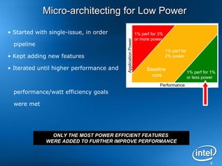
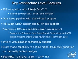
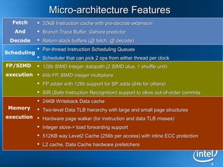
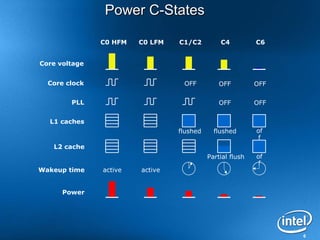
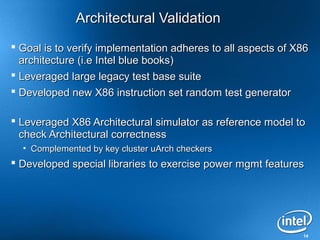
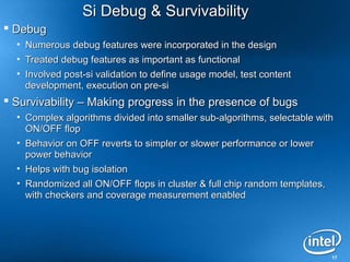
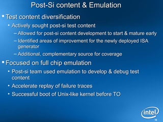
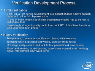
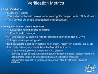
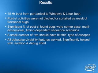
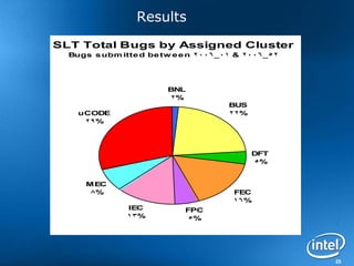
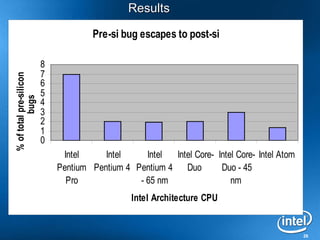
This document discusses the verification of Intel's Atom processor. It describes the key verification challenges, methodology used, and results. The main challenges were verifying a new microarchitecture with aggressive schedules and limited resources. The methodology involved cluster-level validation, functional coverage, architectural validation, and formal verification. Metrics like coverage, bug rates, and a "health of model" indicator were used. The results showed a successful pre-silicon verification with few escapes and debug/survivability features working as intended. Key learnings included the importance of keeping the full-chip design healthy early and putting equal focus on testability features.
2. Agenda
• Atom Introduction
• Verification challenges
• High level verification methodology
• Verification development process and indicators
• Results & key learning's
• Future challenges
2
3. Micro-architecting for Low Power
• Started with single-issue, in order 1% perf for 3%
or more power
Application Power
pipeline
1% perf for
• Kept adding new features 2% power
• Iterated until higher performance and Baseline
1% perf for 1%
core or less power
Performance
performance/watt efficiency goals
were met
ONLY THE MOST POWER EFFICIENT FEATURES
WERE ADDED TO FURTHER IMPROVE PERFORMANCE
3
4. Key Architecture Level Features
• ISA compatible with Intel® Core™ 2
including Intel® SSE3, SSSE3 and Intel®64
• Dual issue pipeline with dual-thread support
• Full width SIMD integer and SP FP add support
• Aggressive TDP/average/idle power management
Support for Enhanced Intel SpeedStep® Technology and ACPI
states including Intel® Deep Power down Technology (C6)
• Intel® Virtualization technology support
• Burst mode capability to enable higher frequency operation
on thermally limited designs
• 800 MHZ – 1.8 GHz, .65W – 2.4W TDP 4
5. Micro-architecture Features
Fetch 32KB Instruction cache with pre-decode extension
And Branch Trace Buffer, Gshare predictor
Decode Return stack buffers (@ fetch, @ decode)
Per-thread Instruction Scheduling Queues
Scheduling
Scheduler that can pick 2 ops from either thread per clock
FP/SIMD 128b SIMD Integer datapath (2 SIMD alus, 1 shuffle unit)
execution 64b FP, SIMD integer multipliers
FP adder with 128b support for SP adds (64b for others)
SIR (Safe Instruction Recognition) support to allow out-of-order commits
24KB Writeback Data cache
Memory Two-level Data TLB hierarchy with large and small page structures
execution Hardware page walker (for instruction and data TLB misses)
Integer store-> load forwarding support
512KB way Level2 Cache (256b per access) with inline ECC protection
L2 cache, Data Cache hardware prefetchers
5
6. Power C-States
C0 HFM C0 LFM C1/C2 C4 C6
Core voltage
Core clock OFF OFF OFF
PLL OFF OFF
L1 caches
flushed flushed of
f
L2 cache
Partial flush of
f
Wakeup time active active
Power
6
7. Global Power Management
• Global clock gating (C states)
• Dynamic frequency and voltage scaling with Enhanced Intel
SpeedStep® Technology (enhanced C states)
• PLL and Front Side Bus IOs shutdown and core voltage
reduction (deep C states)
• Sleep transistors allow dynamic power down of L2 cache
ways (Ultra-drowsy mode in deep C states)
• Sleep transistors in L2 cache allow voltage to be reduced to
inactive logic (Drowsy mode)
• CMOS mode on Front Side Bus
7
8. Agenda
• Atom Introduction
• Verification challenges
• High level verification methodology
• Verification development process and indicators
• Results & key learning's
• Future challenges
8
9. Verification Challenges
New ground up uArchitecture
• Large scale development on validation collaterals
Aggressive development schedule to first TO
Constrained verification resource environment
• More acute for the first half of the project where new
development was taking place
Introduction of significant power mgmt features
Minimize post-si validation qualification cycle, at least from
function/logic perspective
9
10. Agenda
• Atom introduction
• Verification challenges
• High level verification methodology
• Verification development process and indicators
• Results & key learning's
• Future challenges
10
11. High level verification approaches
Cluster level validation & functional coverage
New x86 test case generator for Architecture validation
New power mgmt validation collaterals development
Formal property & model checking verification
X86 legacy database reuse for verifying against Architecture
Focus on debug, testability & survivability features from the
start
Complementary full chip test content from post-si domain
Emulation
11
12. Cluster level validation
Developed new test benches for all clusters (5 HW clusters) in Specman
“e”
Test bench architecture enabled building “super clusters” as appropriate
• Bus + Memory, Front end + scheduler
• Allowed exercising complicated inter-cluster protocol more effectively
Scoreboard + checkers reused at full chip environment
Detailed scoreboard + checker reviews with Architecture + design teams
Random templates + Specman constraints generated tests
New Arch simulator facilitated standalone Ucode validation environment
12
13. Functional Coverage
Significant emphasis on use of functional coverage in all
clusters & full chip
Propriety coverage language specification/collection/analysis
flow
Coverage space specification was result of collaboration with
architecture, design teams
Use coverage to identify test generation & content gap at
cluster and FC environments
Set goals for cluster and full chip functional coverage goals
Could not attain high tape out coverage goals in some areas
- Detailed coverage analysis reviews with all stakeholders
- Post-si validation focused on low coverage areas
13
14. Architectural Validation
Goal is to verify implementation adheres to all aspects of X86
architecture (i.e Intel blue books)
Leveraged large legacy test base suite
Developed new X86 instruction set random test generator
Leveraged X86 Architectural simulator as reference model to
check Architectural correctness
• Complemented by key cluster uArch checkers
Developed special libraries to exercise power mgmt features
14
15. It is all about Power stupid……
Imperative to get the power saving features right at A0
• Early post-si power characterization was key requirement
• Enablement of power management SW development and debug as
soon as possible
Developed validation collaterals to inject random power events
& dynamic checkers for correct behavior
• Power mgmt is collaboration of Ucode, HW & chipset
• High level of random variables to create scenarios
• Detailed checker to verify state & other power related features
State corruption capability as power domain turned off
• Power specification approach was in its infancy
• Developed tools to identify sequential elements & corrupt state as
needed
Clock gating logic traversal capability and coverage
specification
15
16. Formal Verification
Applied model checking
• Selective areas on floating point algorithms with data path
content
• Instruction length decode data path
Extensive use of assertions
• Assumption checking
• Protocols
• Multi-cycle paths
• ~50% of non-complex assertions proven formally
16
17. Si Debug & Survivability
Debug
• Numerous debug features were incorporated in the design
• Treated debug features as important as functional
• Involved post-si validation to define usage model, test content
development, execution on pre-si
Survivability – Making progress in the presence of bugs
• Complex algorithms divided into smaller sub-algorithms, selectable with
ON/OFF flop
• Behavior on OFF reverts to simpler or slower performance or lower
power behavior
• Helps with bug isolation
• Randomized all ON/OFF flops in cluster & full chip random templates,
with checkers and coverage measurement enabled
17
18. Post-Si content & Emulation
Test content diversification
• Actively sought post-si test content
– Allowed for post-si content development to start & mature early
– Identified areas of improvement for the newly deployed ISA
generator
– Additional, complementary source for coverage
Focused on full chip emulation
• Post-si team used emulation to develop & debug test
content
• Accelerate replay of failure traces
• Successful boot of Unix-like kernel before TO
18
19. Agenda
• Atom introduction
• Verification challenges
• High level verification methodology
• Verification development process and indicators
• Results & key learning's
• Future challenges
19
20. Verification Development Process
Light verification
• Split RTL & test bench development into distinct phases & have enough
features to allow full chip execution
• At end of each phase, set of clear acceptance criteria had to be met to
call phase done
• Increasingly stringent quality control to check RTL & test bench code in
data base with each phase
Heavy verification
• Test planning, coverage specification phase, initial exercise
• Template writing, directed test writing, start coverage roll up
• Coverage analysis with feedback to test generation & environment
• More randomness, more injectors, more stress scenarios as new bug
arrival rate showed downward trend
20
21. Verification Metrics
Light Validation
• Stage plan based
• Verification collateral development was tightly coupled with RTL features
• Tight control on phase acceptance criteria content
Heavy verification phase indicators
• % Coverage specification complete
• % Functional coverage
• % Tests written & passing rate for directed scenarios (DFT, DFV)
• % Legacy tests passing rate
• Bug indicators such as incoming rate, open, ready-for-closure, type, etc
• Last but certainly not least, health of model indicator
– Used by many previous generation CPU projects
– Intended to act as RTL functional health indicator to design, project mgmt, etc
– Incorporates impact of unresolved bugs on validation progress
– Incorporates subjective “progress” factor as voted by different areas of
validation
21
22. Health of the model indicator
Atom Health of the Model
100
90
80
70
60
Score
50
40
30
20
10
0
0
Qtr 4 Qtr 3 Qtr 2 Qtr 1 Qtr 0
Tim e to Tapeout
Black – Atom
Pink, Blue, Orange - Previous CPU projects
Green Line – Desired zone
Red Line - Urgent action required zone
22
23. Agenda
• Atom introduction
• Verification challenges
• High level verification methodology
• Verification development process and indicators
• Results & key learning's
• Future challenges
23
24. Results
10 Hr boot from part arrival to Windows & Linux boot
Post-si activities were not blocked or curtailed as result of
functional bugs
Significant % of post-si found bugs were corner case, multi-
dimensional, timing-dependent sequence scenarios
A small number of “we should have hit this” type of escapes
All debug/survivability features worked. Significantly helped
with isolation & debug effort
24
25. Results
SLT Total Bugs by Assigned Cluster
Bugs s ubm itte d be tw e e n 2006_01 & 2006_52
BNL
2%
BUS
uCODE 22%
29%
DFT
5%
M EC
8% FEC
16%
IEC FPC
13% 5%
25
26. Results
Pre-si bug escapes to post-si
8
7
% of total pre-silicon
6
5
bugs
4
3
2
1
0
Intel Intel Intel Intel Core- Intel Core- Intel Atom
Pentium Pentium 4 Pentium 4 Duo Duo - 45
Pro - 65 nm nm
Intel Architecture CPU
26
27. Results
Ultimate indicator of successful result is
Intel® Atom™ powering many products in stores near you !
27
28. Key Learning's
Build & keep full chip healthy as soon as possible
Keep stringent quality control to check-in RTL and/or
validation collaterals in the design database
Putting same focus on DFT, DFV, etc as main stream
functionality pays off in long term
Dig behind the indicators, especially when they show rosy
pictures
Small, highly focused, motivated team can do wonderful
things
28
29. Agenda
• Atom introduction
• Verification challenges
• High level verification methodology
• Verification development process and indicators
• Results & key learnings
• Future challenges
29
30. Future challenges
Effective & systematic coverage specification and
measurement for post-si and how to tie or
leverage pre-si
Ways to capture state & debug, especially as
move to even more integrated multi-core, multi-IP
world
Analog/digital, circuit, process i.e non-logic issues
are starting to dominate post-si qualification cycle
30