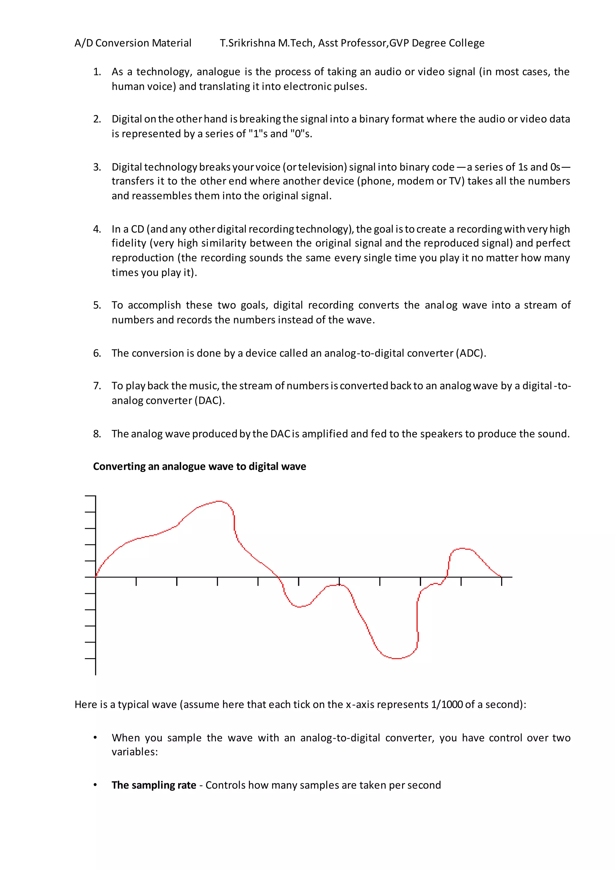
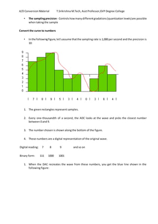
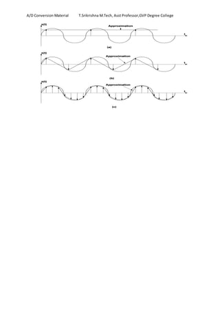
A/D Conversion Material T.Srikrishna M.Tech, Asst Professor,GVP Degree College
1. As a technology, analogue is the process of taking an audio or video signal (in most cases, the
human voice) and translating it into electronic pulses.
2. Digital onthe otherhand isbreakingthe signal into a binary format where the audio or video data
is represented by a series of "1"s and "0"s.
3. Digital technologybreaksyourvoice (ortelevision) signal into binary code—a series of 1s and 0s—
transfers it to the other end where another device (phone, modem or TV) takes all the numbers
and reassembles them into the original signal.
4. In a CD (andany otherdigital recordingtechnology),the goal istocreate a recordingwithveryhigh
fidelity (very high similarity between the original signal and the reproduced signal) and perfect
reproduction (the recording sounds the same every single time you play it no matter how many
times you play it).
5. To accomplish these two goals, digital recording converts the analog wave into a stream of
numbers and records the numbers instead of the wave.
6. The conversion is done by a device called an analog-to-digital converter (ADC).
7. To playback the music,the stream of numbersisconvertedbackto an analogwave by a digital-to-
analog converter (DAC).
8. The analog wave producedbythe DACis amplified and fed to the speakers to produce the sound.
Converting an analogue wave to digital wave
Here is a typical wave (assume here that each tick on the x-axis represents 1/1000 of a second):
• When you sample the wave with an analog-to-digital converter, you have control over two
variables:
• The sampling rate - Controls how many samples are taken per second
A/D Conversion Material T.Srikrishna M.Tech, Asst Professor,GVP Degree College
• The samplingprecision- Controlshow manydifferentgradations(quantization levels)are possible
when taking the sample
Convert the curve to numbers
• In the followingfigure,let'sassume thatthe sampling rate is 1,000 per second and the precision is
10:
1. The green rectangles represent samples.
2. Every one-thousandth of a second, the ADC looks at the wave and picks the closest number
between 0 and 9.
3. The number chosen is shown along the bottom of the figure.
4. These numbers are a digital representation of the original wave.
Digital reading: 7 8 9 and so on
Binary form: 111 1000 1001
1. When the DAC recreates the wave from these numbers, you get the blue line shown in the
following figure:
A/D Conversion Material T.Srikrishna M.Tech, Asst Professor,GVP Degree College
2. You can see that the blue line lostquite abitof the detail originally found in the red line, and that
means the fidelity of the reproduced wave is not very good
3. Thisis the samplingerror.Youreduce samplingerrorby increasing both the sampling rate and the
precision
In these diagrams the rate and the precision have been improved
A/D Conversion Material T.Srikrishna M.Tech, Asst Professor,GVP Degree College
Terminology
Analog: continuouslyvaluedsignal,suchastemperature orspeed,withinfinitepossiblevalues in between
Analog signals – directly measurable quantities in terms of some other quantity
Examples:
Thermometer – mercury height rises as temperature rises (or) Car Speedometer – Needle moves farther
right as you accelerate
Digital: discretely valued signal, such as integers, encoded in binary
Digital Signals –have onlytwostates. For digital computers, we refer to binary states, 0 and 1. “1”
can be on, “0” can be off.
Examples: Light switch can be either on or off (or) Door to a room is either open or closed
A/D Conversion Material T.Srikrishna M.Tech, Asst Professor,GVP Degree College
comparator : The basicprinciple of operation is to use the comparator principle to determine whether or
not to turn on a particular bit of the binary number output
• A comparatoris usedinmany typesof A/Dconverters.
• A comparator isthe simplestinterface fromananalogsignal toa digital signal
• A comparator comparestwovoltage valuesonitstwoinputs
• If the voltage onthe + inputisgreaterthan the voltage onthe - input,the outputwill be a logichigh
• If the voltage onthe + inputislessthanthe voltage onthe - input,the outputwill be alogiclow
If Vin> Vref then Vout= Vcc
If Vin< Vref then Vout= 0
Quantization is the process of converting the sampled continuous Valued signals into discrete-valued
data
The number of possible states that the converter can output is: N=2n
Where n is the number of bits in the AD converter
Example: For a 3 bit A/D converter, N=23
=8.
Analog quantization size: Q= (V max -V min)/N = (10V – 0V)/8 = 1.25V
Analog  Digital Conversion 2-Step Process:
• Quantizing - breaking down analog value is a set of finite states
• Encoding - assigning a digital word or number to each state and matching it to the input signal
Step 1: Quantizing
• You have 0-10V signals. Separate them into a set of discrete states with 1.25V increments. (How
did we get 1.25V? Discussed previous )
Output States Discrete Voltage Ranges (V)
0 0.00-1.25
A/D Conversion Material T.Srikrishna M.Tech, Asst Professor,GVP Degree College
1 1.25-2.50
2 2.50-3.75
3 3.75-5.00
4 5.00-6.25
5 6.25-7.50
6 7.50-8.75
7 8.75-10.0
Step 2. Encoding
Here we assign the digital value (binary number) to each state for the computer to read.
Output
States
Output Binary Equivalent
0 000
1 001
2 010
3 011
4 100
5 101
6 110
7 111
Sampling.
• It is a process of taking a sufficient number of discrete values at point on a waveform that will
define the shape of waveform.
• The more samples you take, the more accurately you will define the waveform.
• It convertsanalogsignal intoseriesof impulses,eachrepresentingamplitude of the signal at given
point…….
• Collect sufficient data for correctly representing a continuous-time signal
A/D Conversion Material T.Srikrishna M.Tech, Asst Professor,GVP Degree College

Analog to Digital Conversion Basics

  • 1.
    A/D Conversion MaterialT.Srikrishna M.Tech, Asst Professor,GVP Degree College 1. As a technology, analogue is the process of taking an audio or video signal (in most cases, the human voice) and translating it into electronic pulses. 2. Digital onthe otherhand isbreakingthe signal into a binary format where the audio or video data is represented by a series of "1"s and "0"s. 3. Digital technologybreaksyourvoice (ortelevision) signal into binary code—a series of 1s and 0s— transfers it to the other end where another device (phone, modem or TV) takes all the numbers and reassembles them into the original signal. 4. In a CD (andany otherdigital recordingtechnology),the goal istocreate a recordingwithveryhigh fidelity (very high similarity between the original signal and the reproduced signal) and perfect reproduction (the recording sounds the same every single time you play it no matter how many times you play it). 5. To accomplish these two goals, digital recording converts the analog wave into a stream of numbers and records the numbers instead of the wave. 6. The conversion is done by a device called an analog-to-digital converter (ADC). 7. To playback the music,the stream of numbersisconvertedbackto an analogwave by a digital-to- analog converter (DAC). 8. The analog wave producedbythe DACis amplified and fed to the speakers to produce the sound. Converting an analogue wave to digital wave Here is a typical wave (assume here that each tick on the x-axis represents 1/1000 of a second): • When you sample the wave with an analog-to-digital converter, you have control over two variables: • The sampling rate - Controls how many samples are taken per second
  • 2.
    A/D Conversion MaterialT.Srikrishna M.Tech, Asst Professor,GVP Degree College • The samplingprecision- Controlshow manydifferentgradations(quantization levels)are possible when taking the sample Convert the curve to numbers • In the followingfigure,let'sassume thatthe sampling rate is 1,000 per second and the precision is 10: 1. The green rectangles represent samples. 2. Every one-thousandth of a second, the ADC looks at the wave and picks the closest number between 0 and 9. 3. The number chosen is shown along the bottom of the figure. 4. These numbers are a digital representation of the original wave. Digital reading: 7 8 9 and so on Binary form: 111 1000 1001 1. When the DAC recreates the wave from these numbers, you get the blue line shown in the following figure:
  • 3.
    A/D Conversion MaterialT.Srikrishna M.Tech, Asst Professor,GVP Degree College 2. You can see that the blue line lostquite abitof the detail originally found in the red line, and that means the fidelity of the reproduced wave is not very good 3. Thisis the samplingerror.Youreduce samplingerrorby increasing both the sampling rate and the precision In these diagrams the rate and the precision have been improved
  • 4.
    A/D Conversion MaterialT.Srikrishna M.Tech, Asst Professor,GVP Degree College Terminology Analog: continuouslyvaluedsignal,suchastemperature orspeed,withinfinitepossiblevalues in between Analog signals – directly measurable quantities in terms of some other quantity Examples: Thermometer – mercury height rises as temperature rises (or) Car Speedometer – Needle moves farther right as you accelerate Digital: discretely valued signal, such as integers, encoded in binary Digital Signals –have onlytwostates. For digital computers, we refer to binary states, 0 and 1. “1” can be on, “0” can be off. Examples: Light switch can be either on or off (or) Door to a room is either open or closed
  • 5.
    A/D Conversion MaterialT.Srikrishna M.Tech, Asst Professor,GVP Degree College comparator : The basicprinciple of operation is to use the comparator principle to determine whether or not to turn on a particular bit of the binary number output • A comparatoris usedinmany typesof A/Dconverters. • A comparator isthe simplestinterface fromananalogsignal toa digital signal • A comparator comparestwovoltage valuesonitstwoinputs • If the voltage onthe + inputisgreaterthan the voltage onthe - input,the outputwill be a logichigh • If the voltage onthe + inputislessthanthe voltage onthe - input,the outputwill be alogiclow If Vin> Vref then Vout= Vcc If Vin< Vref then Vout= 0 Quantization is the process of converting the sampled continuous Valued signals into discrete-valued data The number of possible states that the converter can output is: N=2n Where n is the number of bits in the AD converter Example: For a 3 bit A/D converter, N=23 =8. Analog quantization size: Q= (V max -V min)/N = (10V – 0V)/8 = 1.25V Analog  Digital Conversion 2-Step Process: • Quantizing - breaking down analog value is a set of finite states • Encoding - assigning a digital word or number to each state and matching it to the input signal Step 1: Quantizing • You have 0-10V signals. Separate them into a set of discrete states with 1.25V increments. (How did we get 1.25V? Discussed previous ) Output States Discrete Voltage Ranges (V) 0 0.00-1.25
  • 6.
    A/D Conversion MaterialT.Srikrishna M.Tech, Asst Professor,GVP Degree College 1 1.25-2.50 2 2.50-3.75 3 3.75-5.00 4 5.00-6.25 5 6.25-7.50 6 7.50-8.75 7 8.75-10.0 Step 2. Encoding Here we assign the digital value (binary number) to each state for the computer to read. Output States Output Binary Equivalent 0 000 1 001 2 010 3 011 4 100 5 101 6 110 7 111 Sampling. • It is a process of taking a sufficient number of discrete values at point on a waveform that will define the shape of waveform. • The more samples you take, the more accurately you will define the waveform. • It convertsanalogsignal intoseriesof impulses,eachrepresentingamplitude of the signal at given point……. • Collect sufficient data for correctly representing a continuous-time signal
  • 7.
    A/D Conversion MaterialT.Srikrishna M.Tech, Asst Professor,GVP Degree College