This document discusses key concepts in digital audio, including:
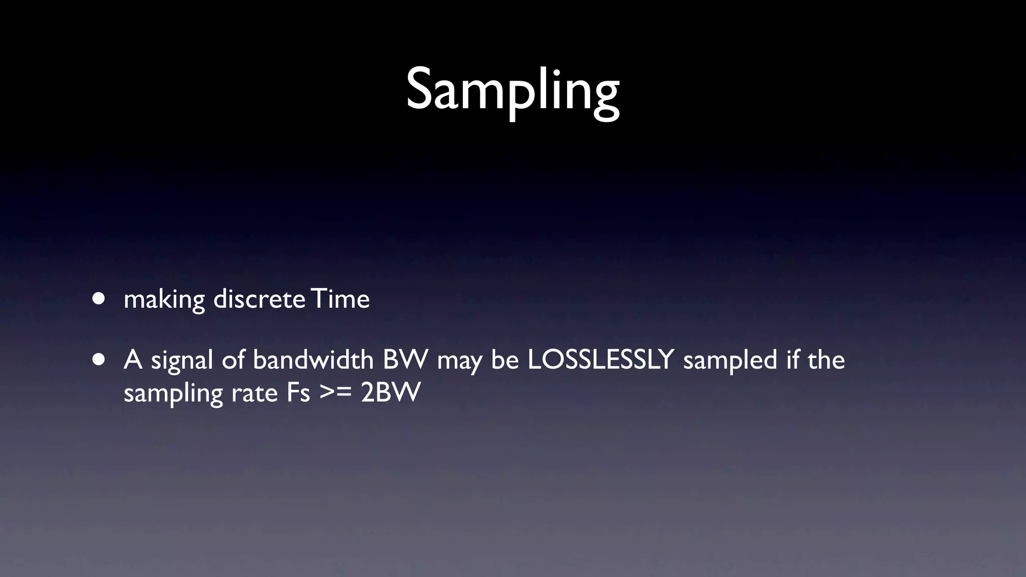
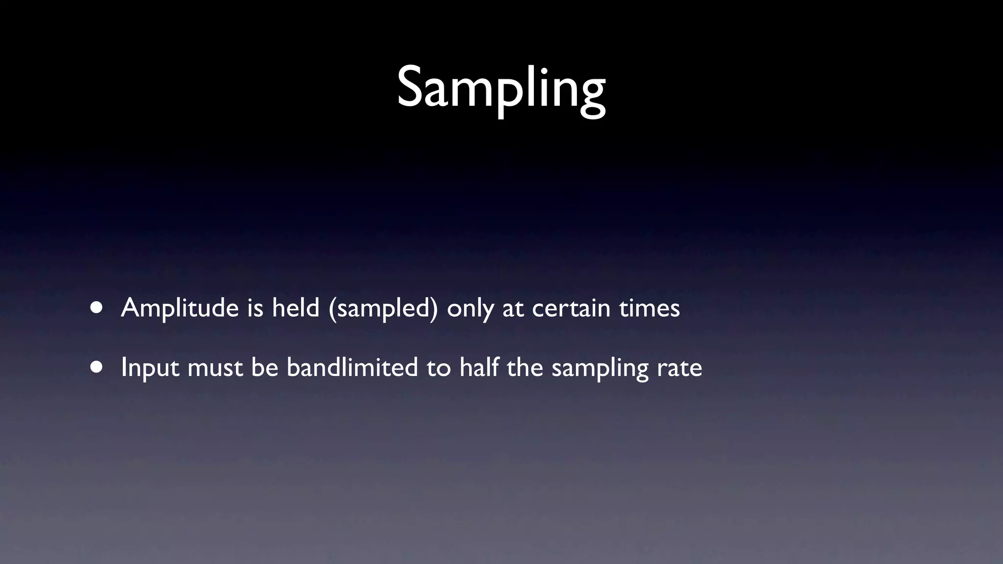
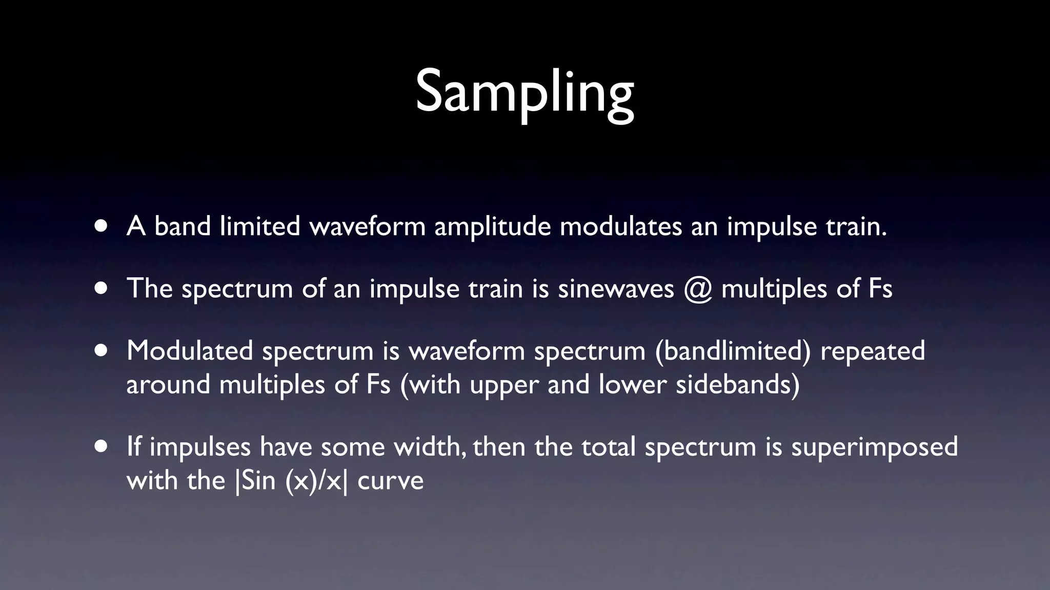
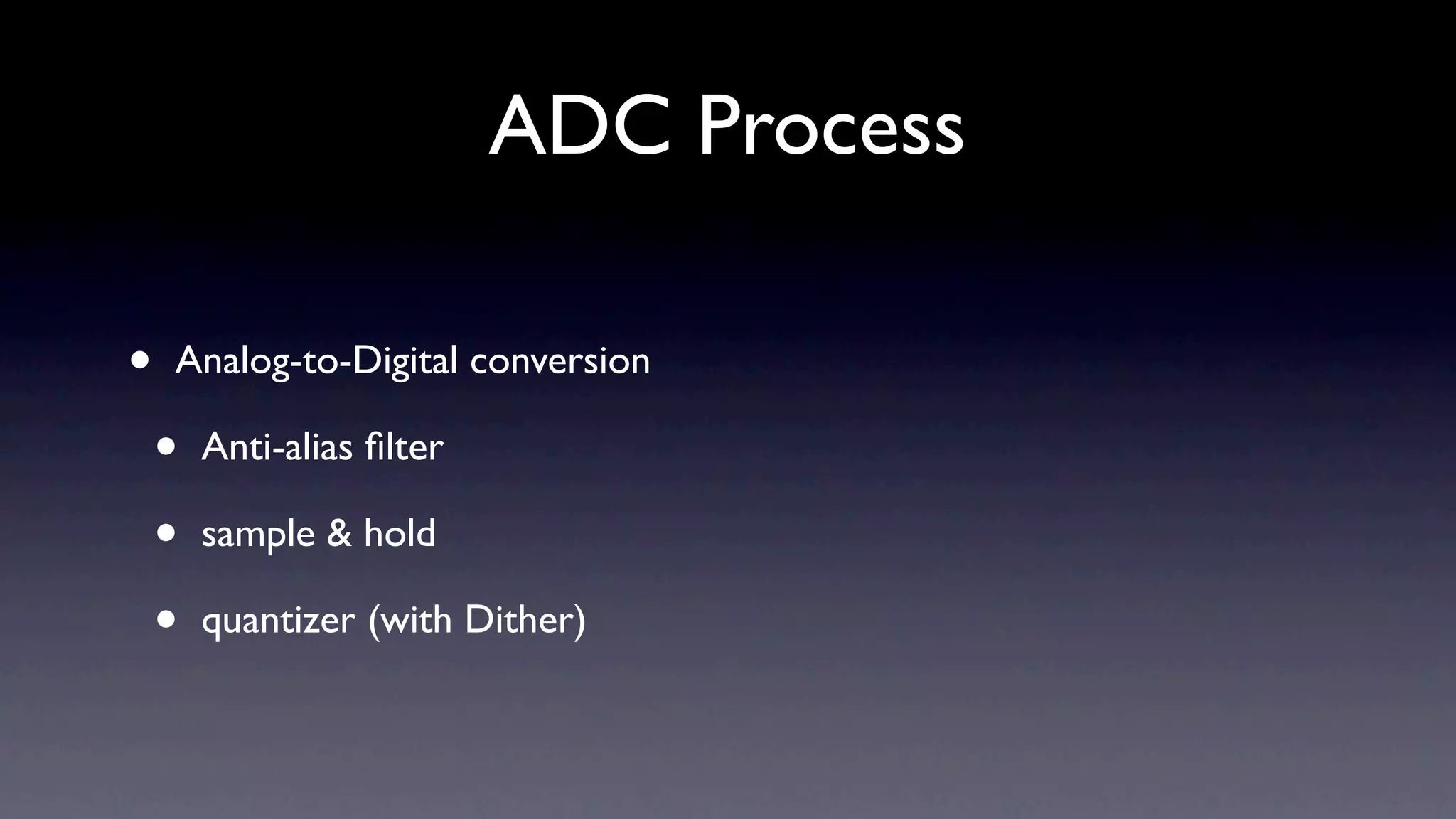
1) Digital audio is discrete in both time and amplitude, where analog is continuous. Sampling converts an analog signal to digital by taking discrete time and amplitude samples.
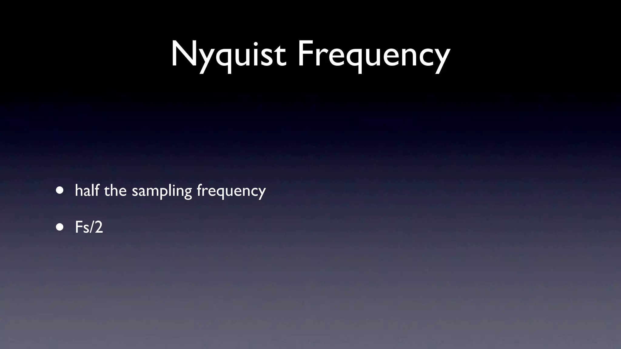
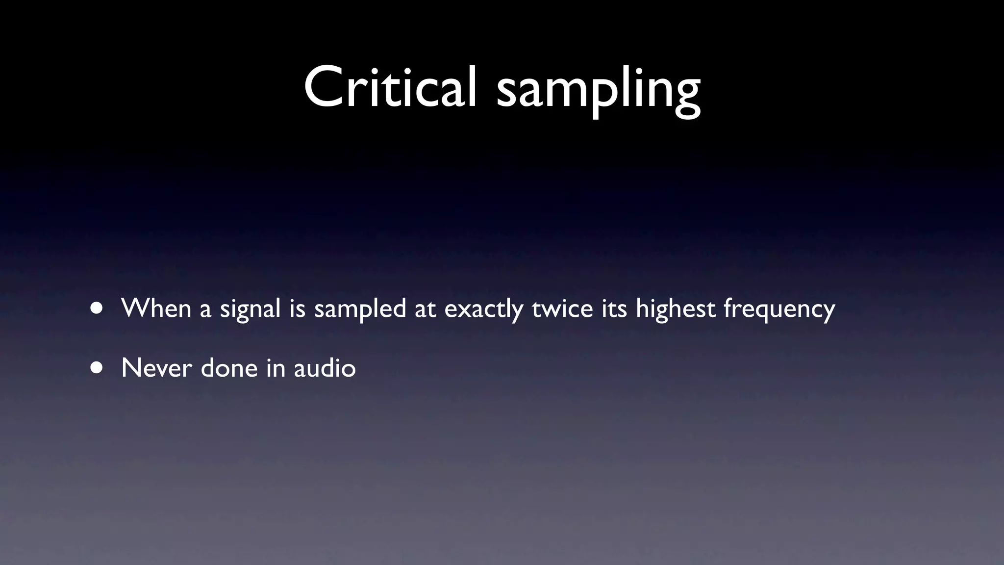
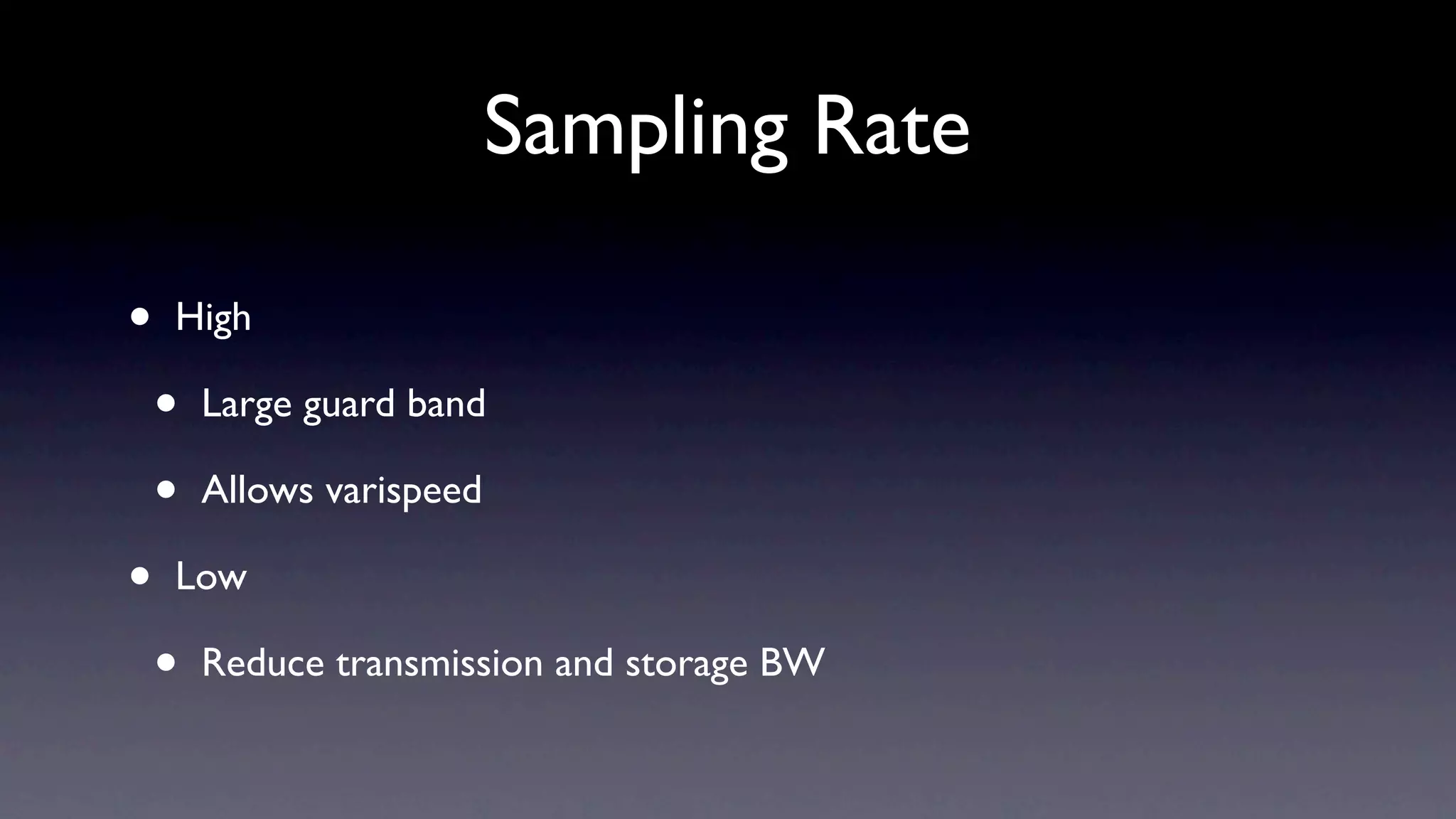
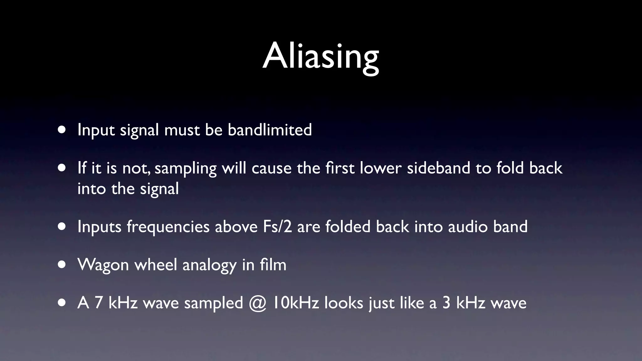
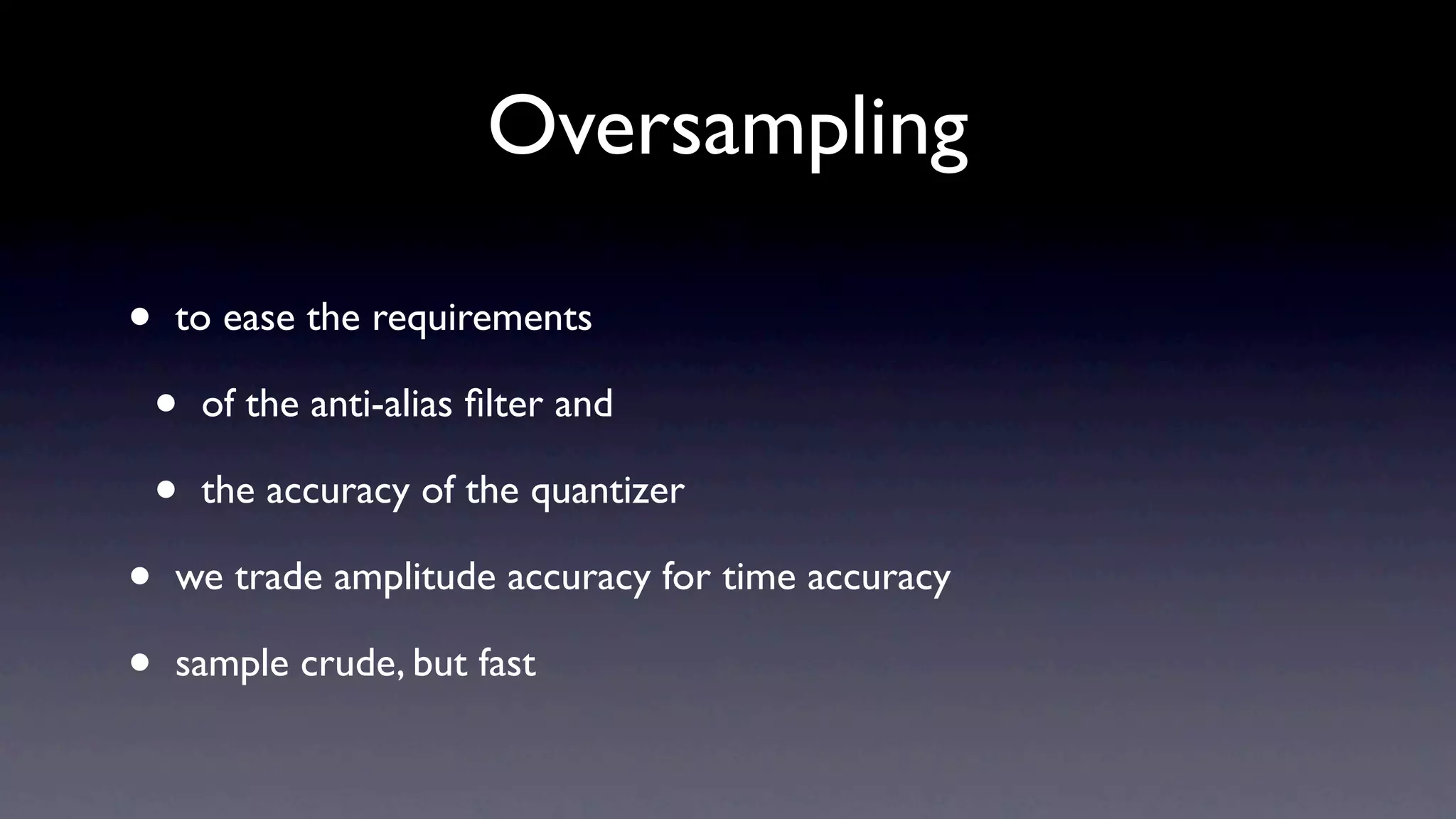
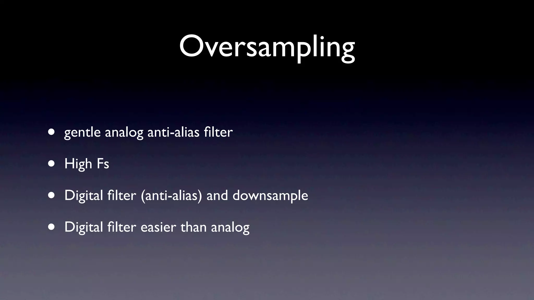
2) For lossless sampling, the sampling rate must be at least twice the bandwidth of the analog signal to avoid aliasing.
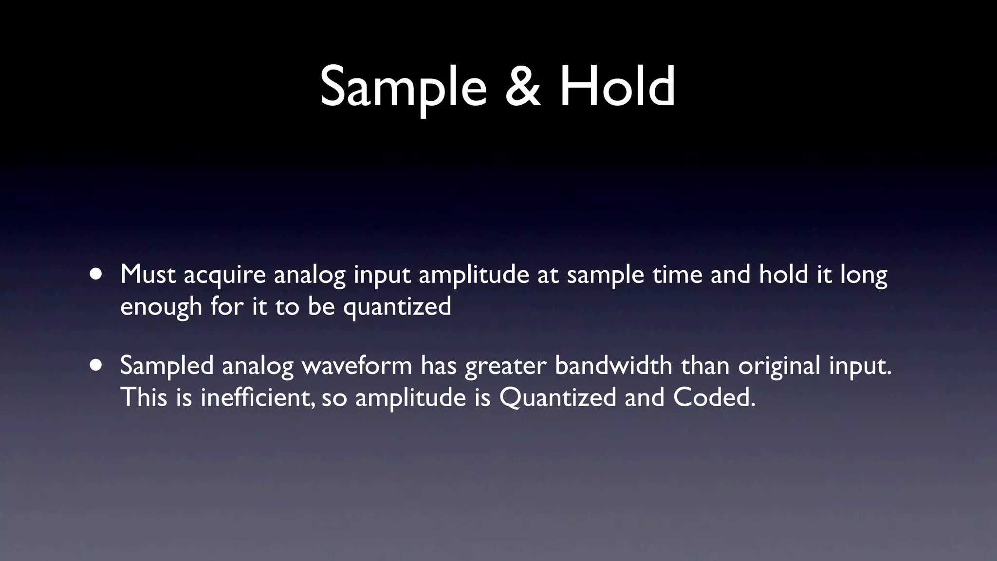
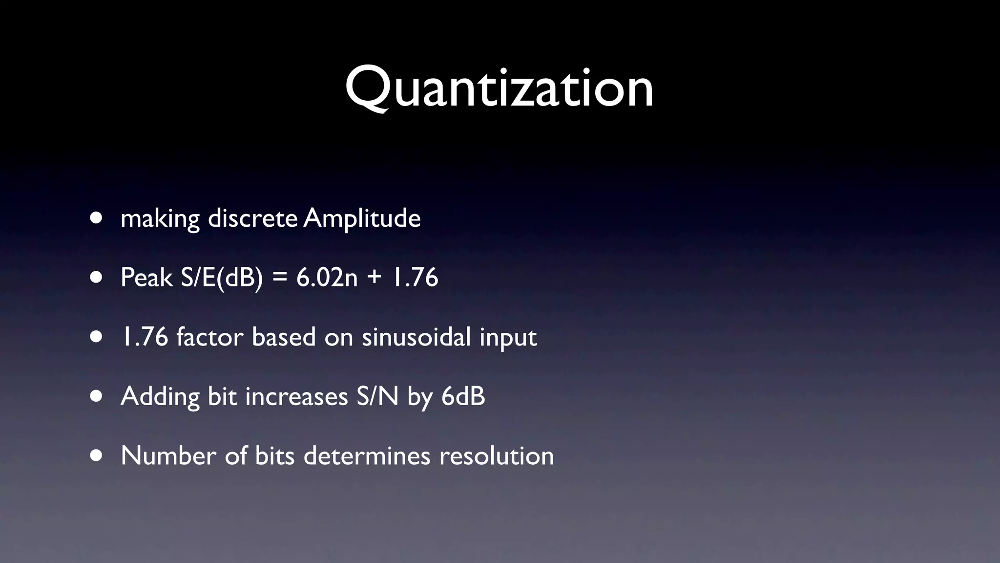
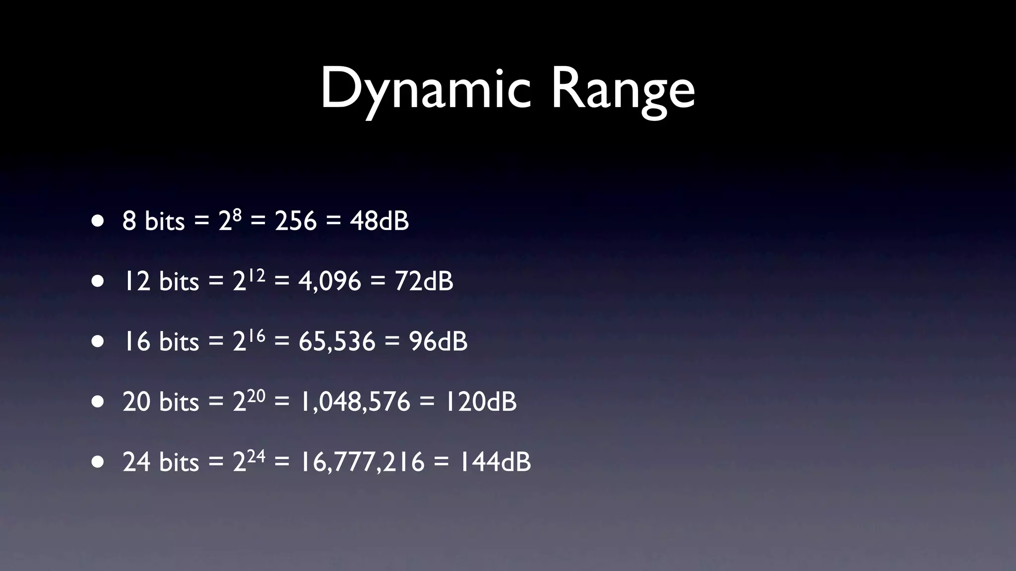
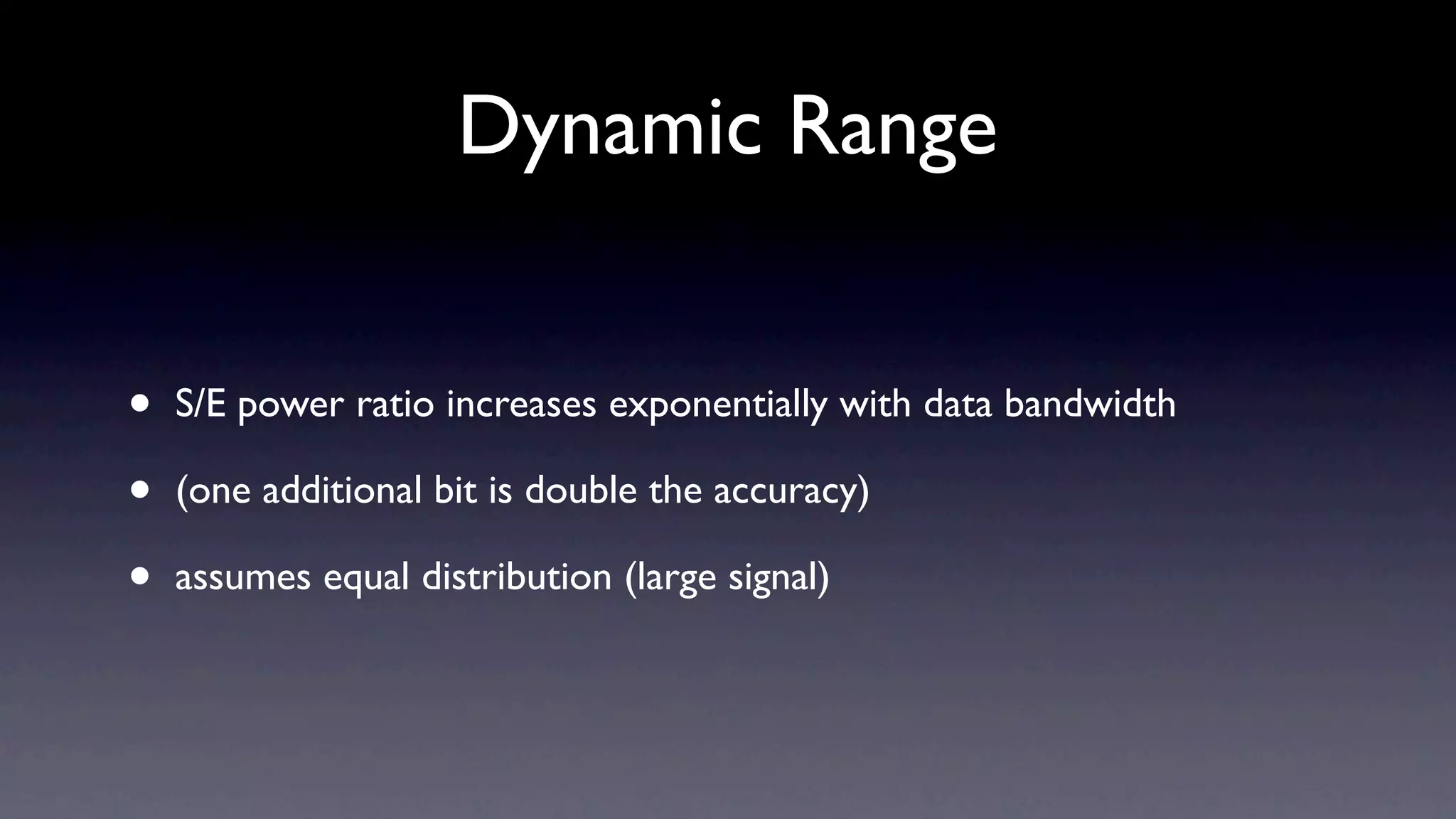
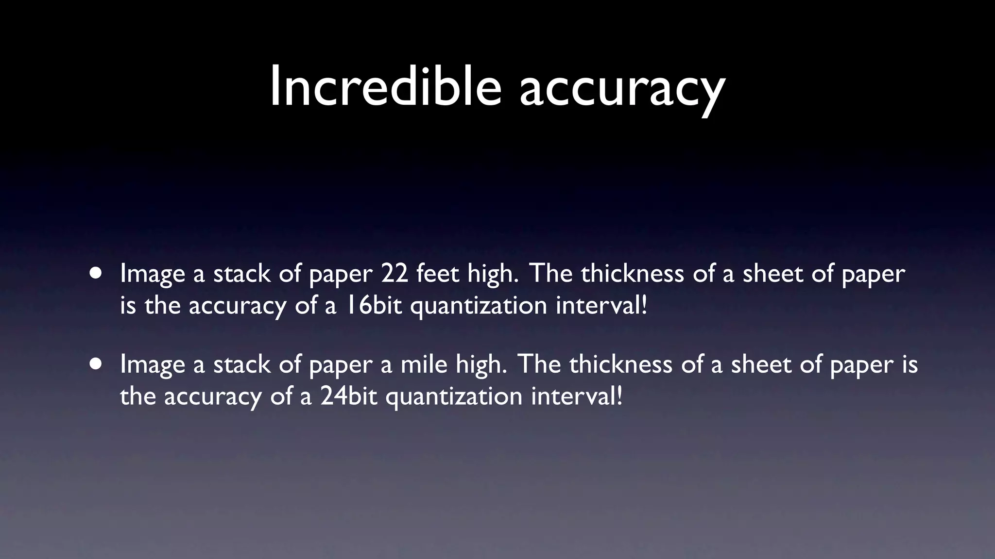
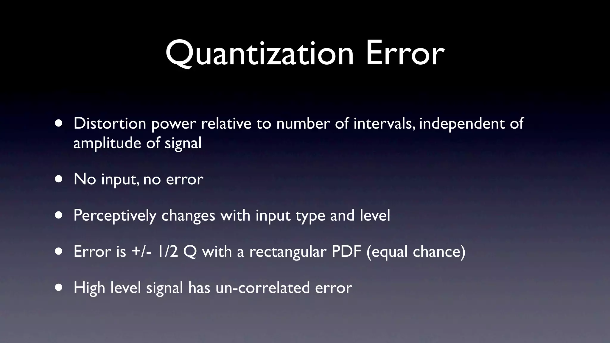
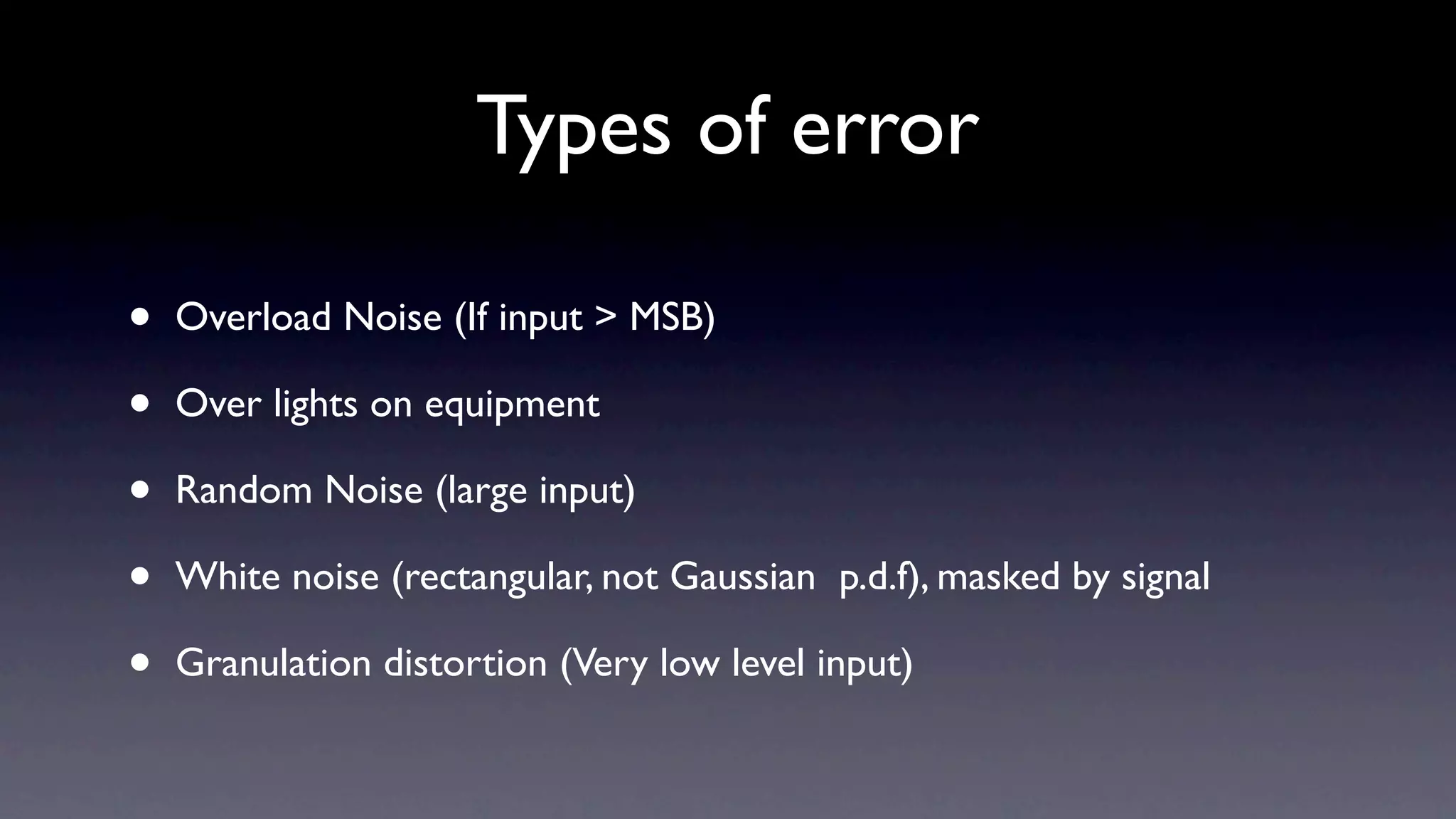
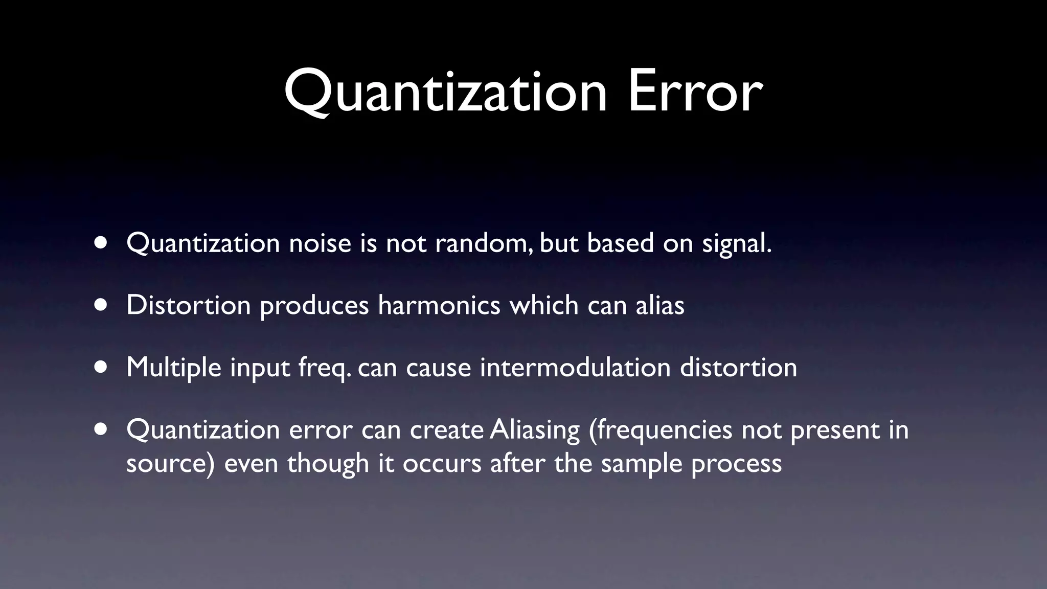
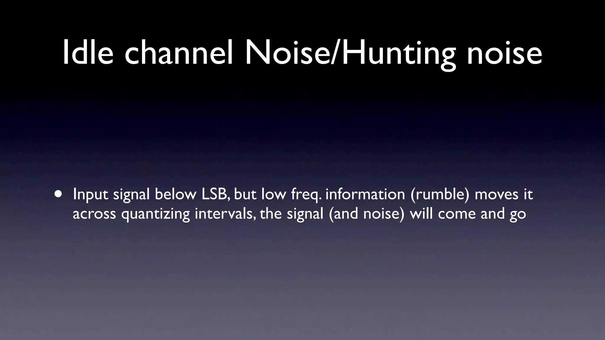
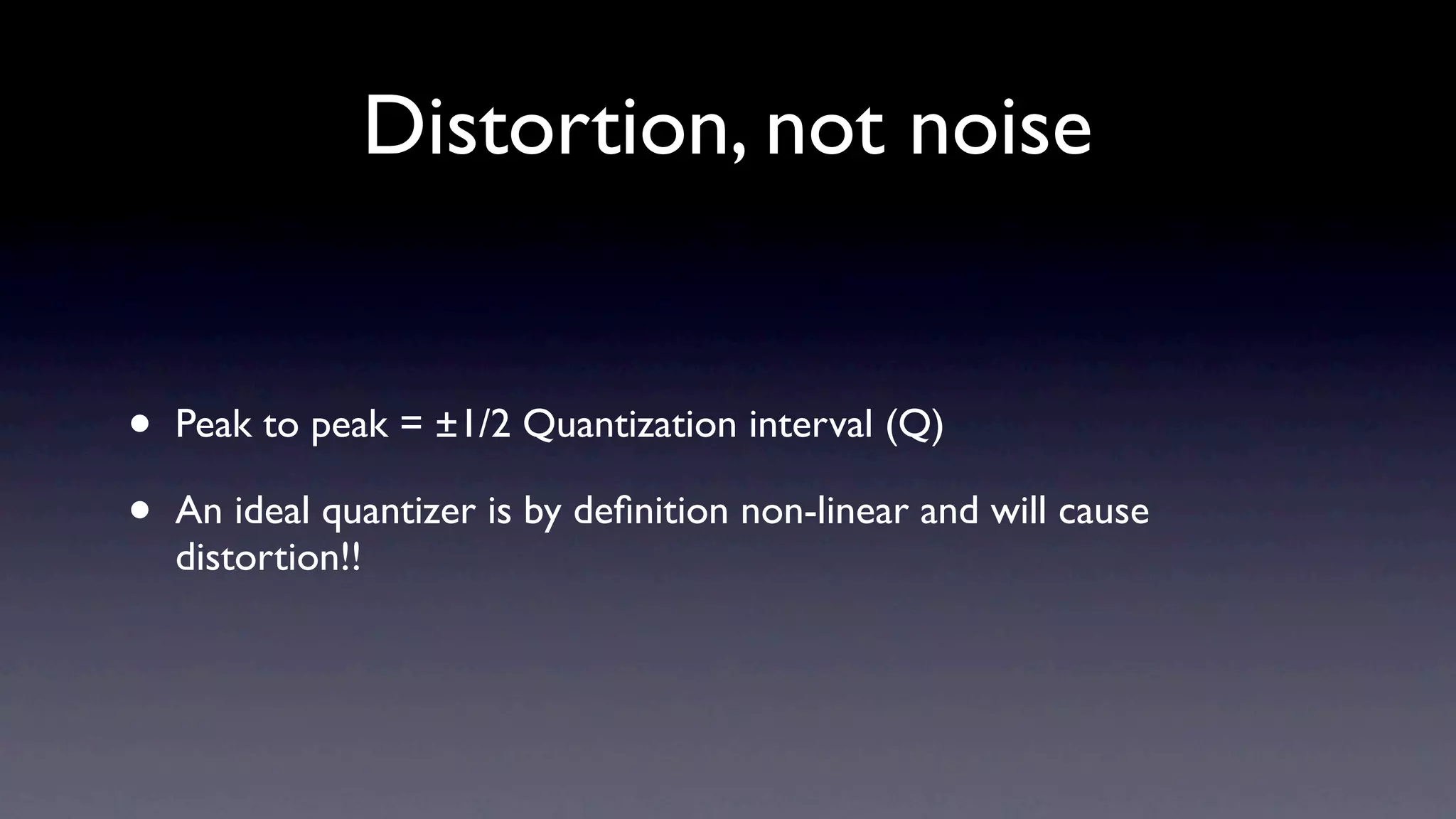
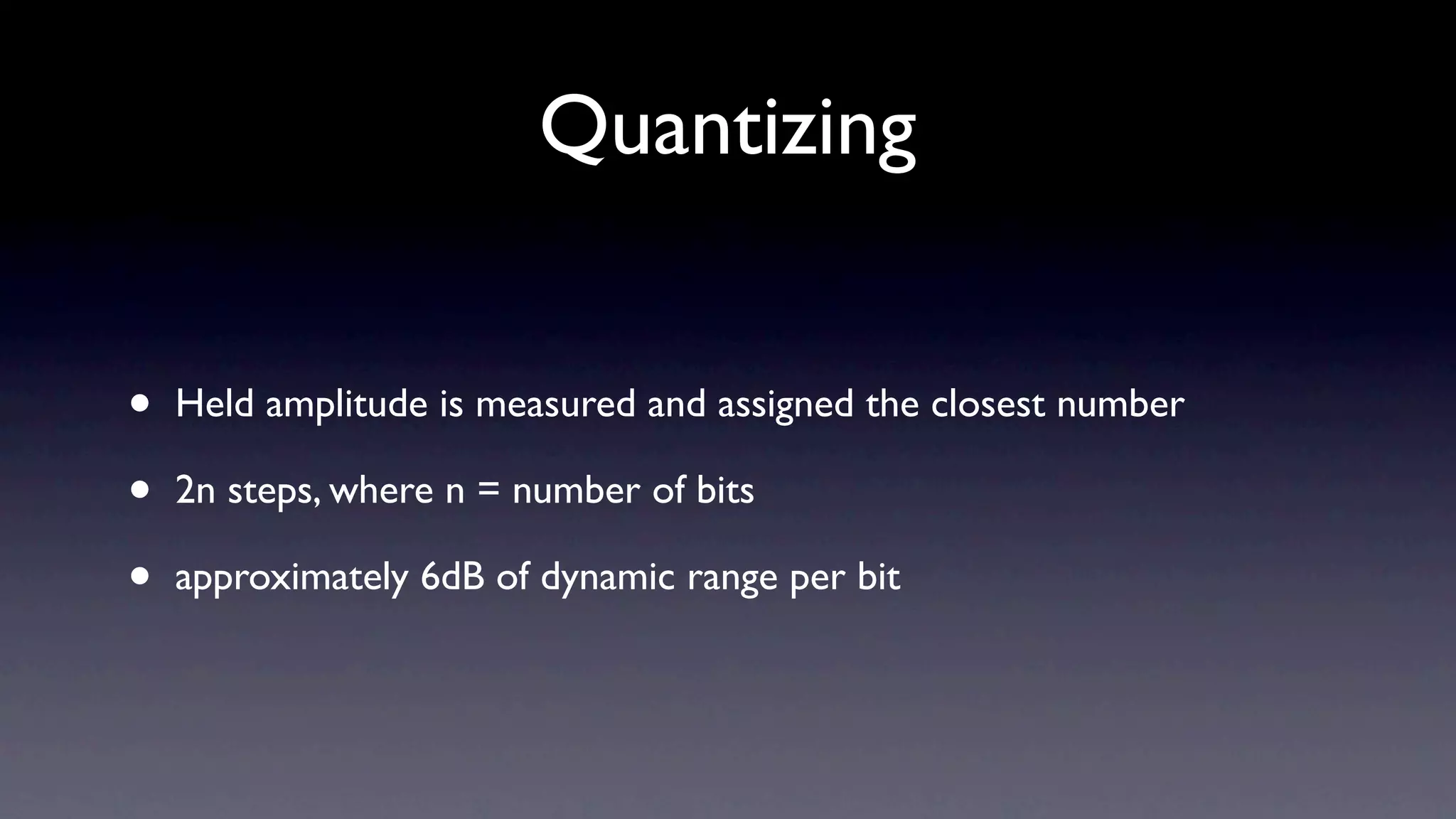
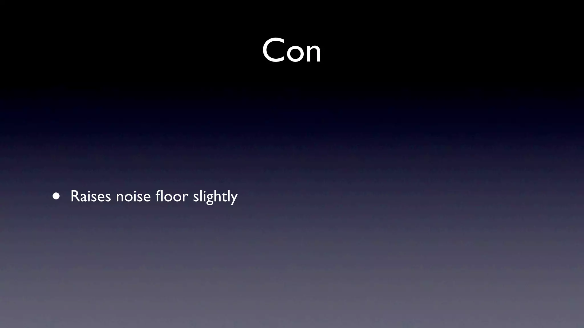
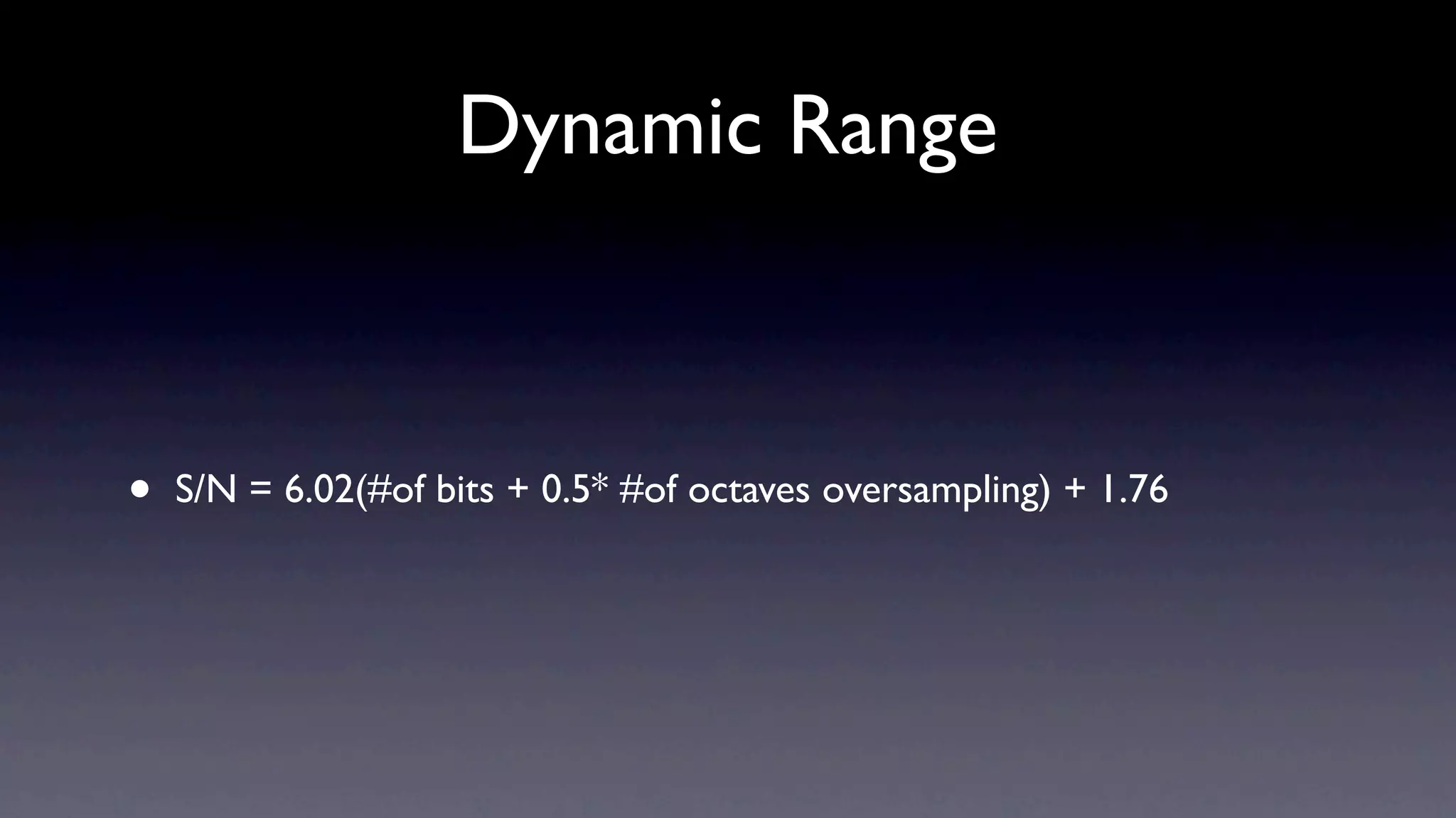
3) Quantization converts the sampled amplitude values to discrete digital values. More bits provide higher resolution and dynamic range but introduce quantization error and noise.
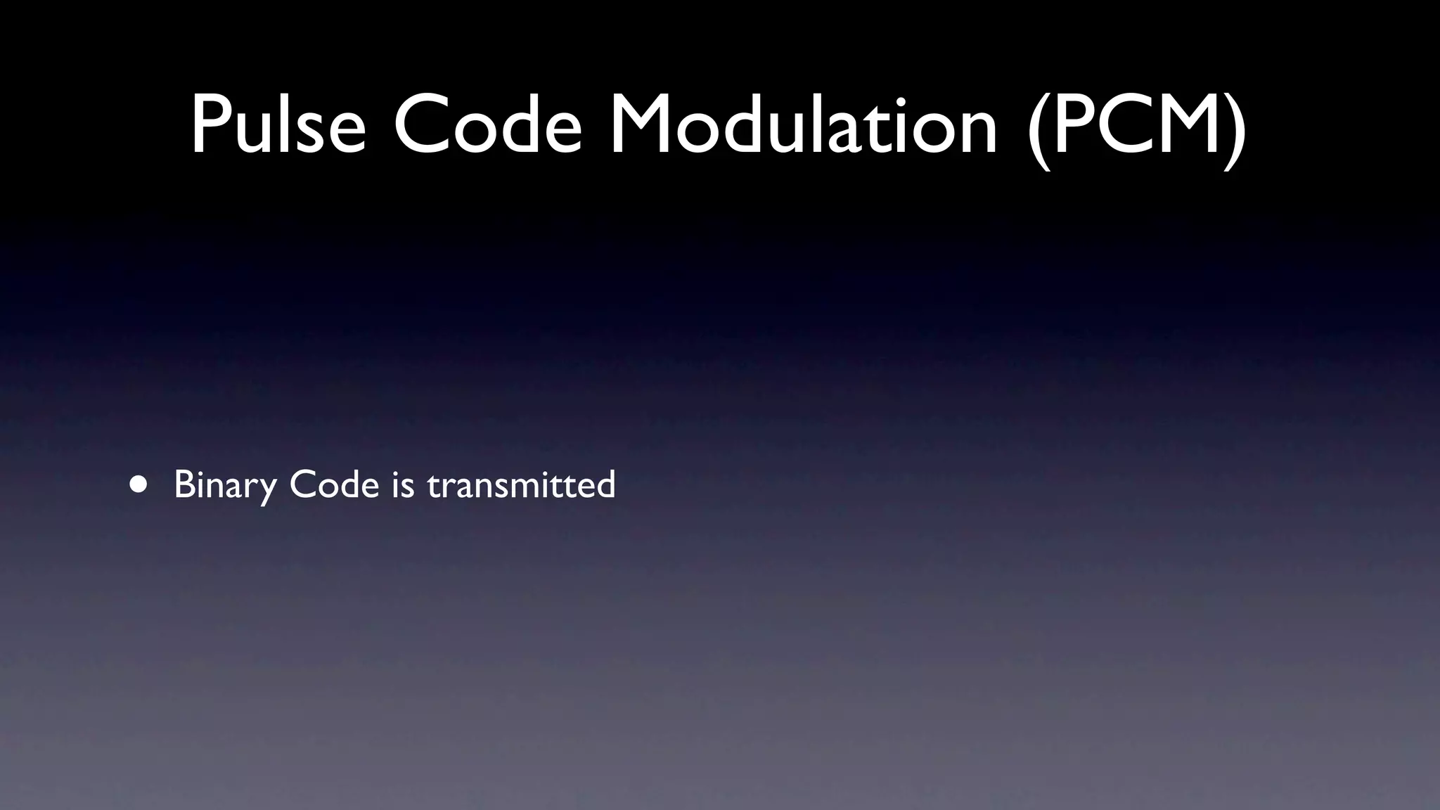
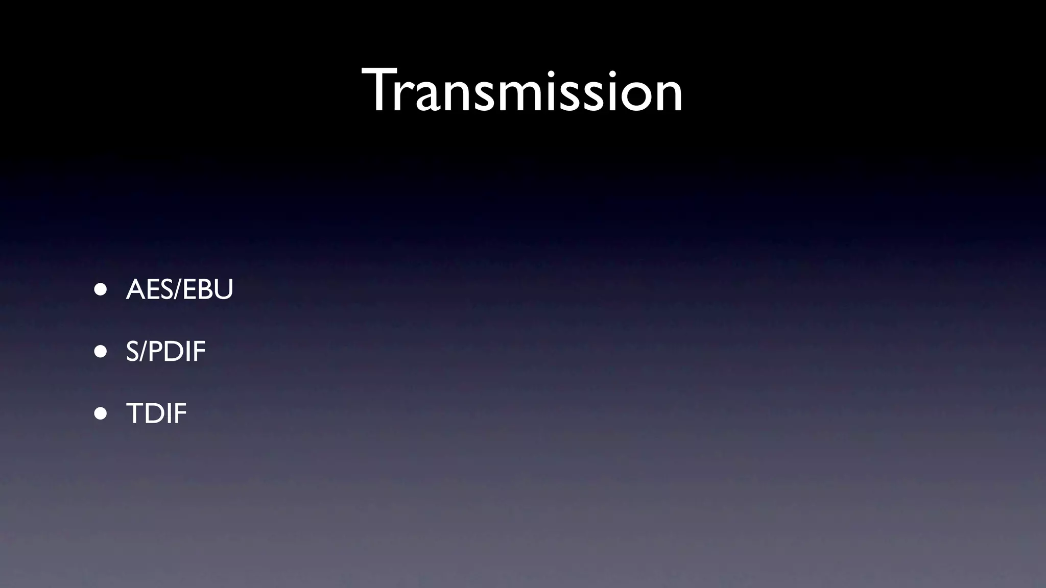
4) Digital audio can be transmitted via various standards like AES/EBU and S/PDIF using pulse code modulation to encode the digital samples into a binary data stream. O