Download as PDF, PPTX

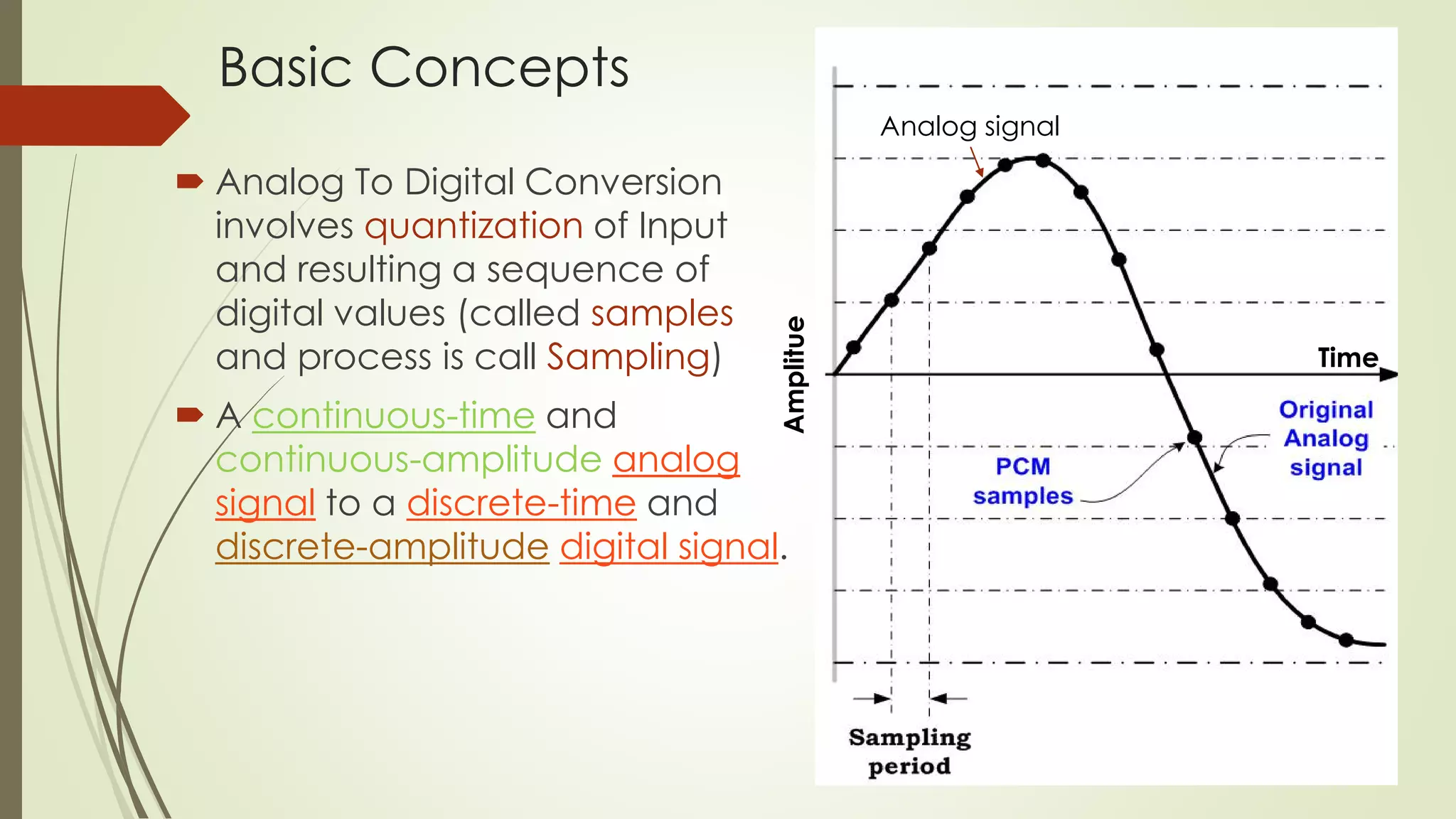
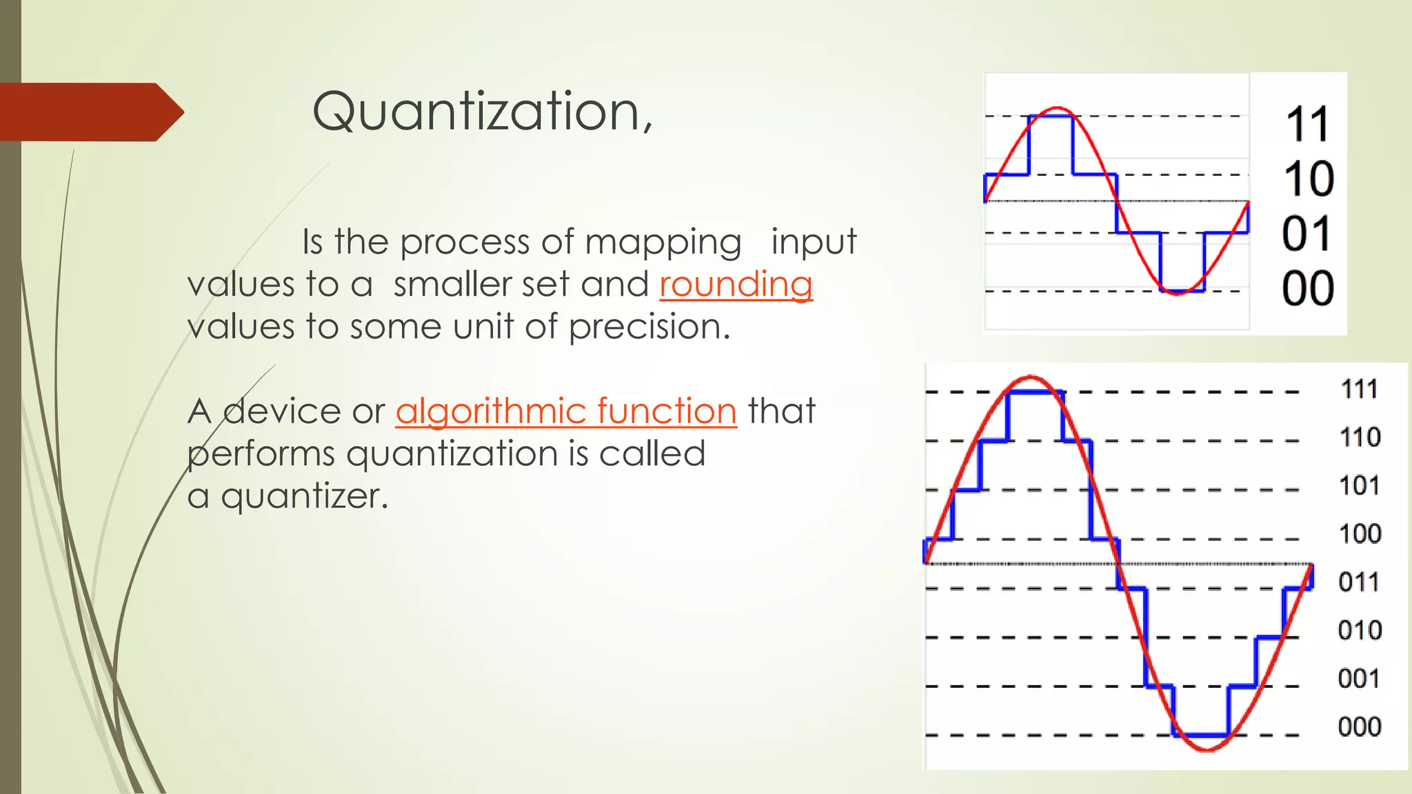
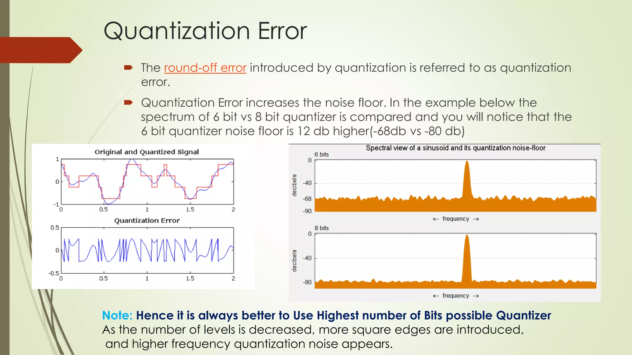
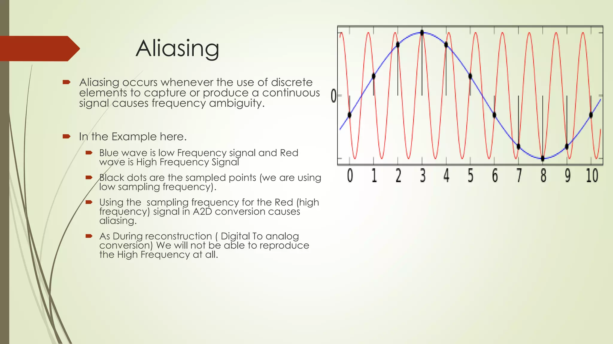

This document discusses the concepts of analog to digital conversion. It describes that analog to digital conversion involves quantizing an analog input signal into a sequence of digital samples through a process called sampling. It discusses key concepts like sampling rate, quantization, quantization error, aliasing, and resolution. Sampling is the process of taking measurements of a continuous signal at regular intervals. Quantization is the process of mapping input values to a smaller set of values with a certain precision level, which introduces quantization error.


