Downloaded 358 times

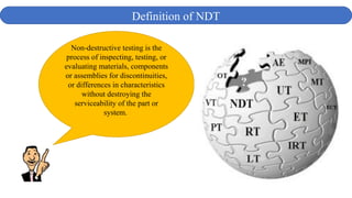
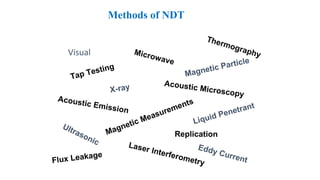
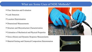
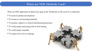
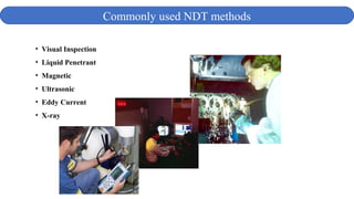
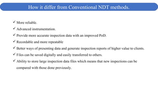
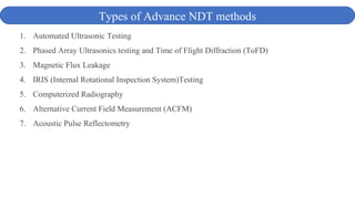
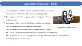
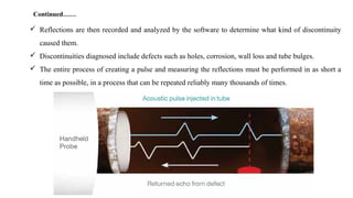
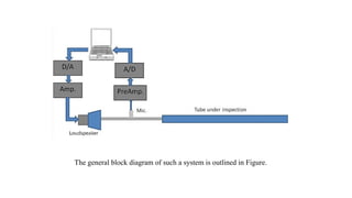
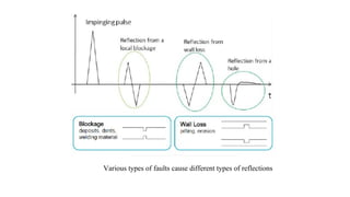
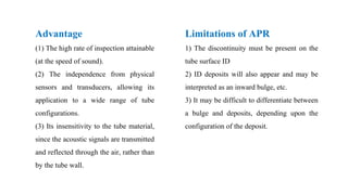


The document discusses various advanced non-destructive testing methods. It defines non-destructive testing and lists common NDT methods. It then describes several advanced NDT methods in more detail, including automated ultrasonic testing, phased array ultrasonics testing, time of flight diffraction, magnetic flux leakage testing, alternative current field measurement, and acoustic pulse reflectometry. The advanced methods provide more accurate inspections with improved detection capabilities compared to conventional NDT techniques.


![[Deck] What's New in Spark-Iceberg Integration via DSV2.pptx](https://cdn.slidesharecdn.com/ss_thumbnails/deckwhatsnewinspark-icebergintegrationviadsv2-260210005337-25955b12-thumbnail.jpg?width=640&height=640&fit=bounds)


