05/01/2025 Title pagedisclosure applies.
2
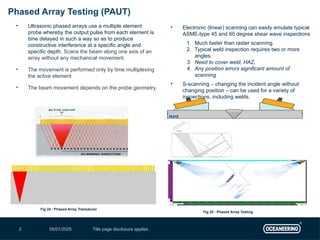
Phased Array Testing (PAUT)
• Ultrasonic phased arrays use a multiple element
probe whereby the output pulse from each element is
time delayed in such a way so as to produce
constructive interference at a specific angle and
specific depth. Scans the beam along one axis of an
array without any mechanical movement.
• The movement is performed only by time multiplexing
the active element
• The beam movement depends on the probe geometry.
• Electronic (linear) scanning can easily emulate typical
ASME-type 45 and 60 degree shear wave inspections
1. Much faster than raster scanning.
2. Typical weld inspection requires two or more
angles.
3. Need to cover weld, HAZ,
4. Any position errors significant amount of
scanning
• S-scanning – changing the incident angle without
changing position – can be used for a variety of
inspections, including welds.
Fig 25 : Phased Array Testing
Fig 24 : Phased Array Transducer
3.
05/01/2025 Title pagedisclosure applies.
3
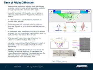
• Measuring the amplitude of reflected signal is a relatively
unreliable method of sizing defects because the amplitude
strongly depends on the orientation of the crack.
• Instead of amplitude, TOFD uses the time of flight of an
ultrasonic pulse to determine the position and size of a
reflector.
• In a TOFD system, a pair of ultrasonic probes sits on
opposite sides of a weld.
• One of the probes, the transmitter, emits an ultrasonic
pulse that is picked up by the probe on the other side, the
receiver.
• In undamaged pipes, the signals picked up by the receiver
probe are from two waves peaks: one that travels along the
surface and one that reflects off the far wall.
• When a crack is present, there is a diffraction of the
ultrasonic wave from the tip(s) of the crack.
• Using the measured time of flight of the pulse, the depth of
a crack tips can be calculated automatically by simple
trigonometry.
• Diffraction defined as the bending of waves around the
corners of an obstacle or through an aperture into the
region of geometrical shadow of the obstacle/aperture. The
diffracting object or aperture effectively becomes a
secondary source of the propagating wave.
Time of Flight Diffraction
Fig 26 : TOFD weld Inspection
4.
05/01/2025 Title pagedisclosure applies.
4
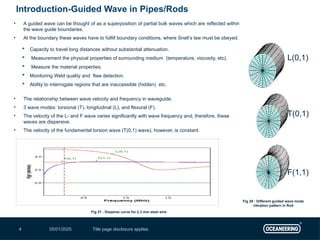
Introduction-Guided Wave in Pipes/Rods
F(1,1)
T(0,1)
L(0,1)
• A guided wave can be thought of as a superposition of partial bulk waves which are reflected within
the wave guide boundaries.
• At the boundary these waves have to fulfill boundary conditions, where Snell’s law must be obeyed.
Capacity to travel long distances without substantial attenuation.
Measurement the physical properties of surrounding medium (temperature, viscosity, etc).
Measure the material properties.
Monitoring Weld quality and flaw detection.
Ability to interrogate regions that are inaccessible (hidden) etc.
• The relationship between wave velocity and frequency in waveguide.
• 3 wave modes: torsional (T), longitudinal (L), and flexural (F).
• The velocity of the L- and F wave varies significantly with wave frequency and, therefore, these
waves are dispersive.
• The velocity of the fundamental torsion wave (T(0,1) wave), however, is constant.
Fig 27 : Disperse curve for 2.3 mm steel wire
Fig 28 : Different guided wave mode
vibration pattern in Rod
05/01/2025 Title pagedisclosure applies.
6
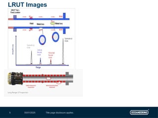
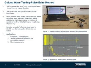
• The transducer will send T(0,1) mode guided wave
through the rod in axial direction.
• The wave travel path guided by the rod outer
boundaries.
• When ever the wave packet interact with the defect
part of the wave will reflect back which will be
collected by the Pulsar receiver in the form of
Amplitude vs. Time of flight/ Distance travelled as
shown in fig.
• Here the amount of reflecting signal used to
identify and characterize the defect size and
nature.
• Applications
1. Corrosion/ Crack detection
2. Temperature measurement of the
surrounding medium.
3. Flow measurements
Guided Wave Testing-Pulse Echo Method
Figure 32 : Amplitude vs. distance plot of ultrasound signal
Figure 31: Pulse echo method of guided wave generation and defect detection
7.
05/01/2025 Title pagedisclosure applies.
7
• The transducer will send T(0,1) mode guided wave
through the rod in axial direction.
• The wave travel path guided by the rod outer boundaries.
• When ever the wave packet interact with the defect part of
the wave will reflect back and the remaining energy
continue to propagate further.
• The amount of reflecting energy and transmitted energy
will vary depends on the cross-sectional material loss and
axial length and defect nature.
• The receiver separated by a distance will collects the
transmitted amount of energy.
• Here the amount of transmitted signal used to identify and
characterize the defect size and nature.
Applications
1. Corrosion/ Crack detection
2. Temperature measurement of the surrounding medium.
3. Flow measurements
Through Transmission (TT) Method
Figure 30 : Amplitude vs. distance plot of ultrasound signal (TT method)
Figure 29 : Through transmission (TT) method of guided wave
generation and detection
8.
05/01/2025 Title pagedisclosure applies.
8
• Eddy current testing is particularly well suited for
detecting surface cracks but can also be used to
make electrical conductivity and coating thickness
measurements.
• Here a small surface probe is scanned over the
part surface in an attempt to detect a crack.
• Periodically, power plants are shutdown for
inspection.
• Inspectors feed eddy current probes into heat
exchanger tubes to check for corrosion damage
• Link.
• Further Study
Eddy Current Testing
Fig 12 : Eddy Current Testing Principle
Fig 13 : Eddy Current Testing of casting sample
Fig 14 : Eddy Current Testing of tubes Fig 15 : Eddy Current Testing of tubes Signal
9.
05/01/2025 Title pagedisclosure applies.
9
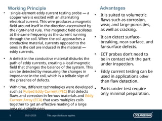
Working Principle
• single-element eddy current testing probe — a
copper wire is excited with an alternating
electrical current. This wire produces a magnetic
field around itself in the direction ascertained by
the right-hand rule. This magnetic field oscillates
at the same frequency as the current running
through the coil. When the coil approaches a
conductive material, currents opposed to the
ones in the coil are induced in the material —
eddy currents.
• A defect in the conductive material disturbs the
path of eddy currents, creating a local magnetic
field that changes the balance of the system. This
can be detected by measuring the changes in
impedance in the coil, which is a telltale sign of
the presence of defects.
• With time, different technologies were developed
such as Pulsed Eddy Current (PEC) that detects
flaws and corrosion in ferrous materials and Eddy
Current Array (ECA) that uses multiples coils
together to get an effective reading of a large
area on a single pass
Advantages
• It is suited to volumetric
flaws such as corrosion,
wear, and large porosities,
as well as cracking.
• It can detect surface-
breaking, near-surface, and
far-surface defects.
• ECT probes don’t need to
be in contact with the part
under inspection.
• Eddy current testing can be
used in applications other
than flaw detection.
• Parts under test require
only minimal preparation.
10.
05/01/2025 Title pagedisclosure applies.
10
• IRIS Technology : Ultrasonic internal rotary inspection System
• Prerequisite : The tubes needs to fill with water
• Internal rotary inspection system (IRIS) is an ultrasonic method for the nondestructive testing of pipes and tubes. The
IRIS probe is inserted into a tube that is flooded with water, and the probe is pulled out slowly as the data is displayed
and recorded
• It is sensitive to ID / OD deposits and fins, which are not defects. It is unable to detect cracking
• Inspection speed is typically 2 to 4 inches/sec. IRIS requires the tubes to be thoroughly cleaned for ultrasonic coupling
• Because IRIS is an ultrasonic technique, it requires a couplant. In this case, water. Tubes under test must therefore
first be flooded to use this technique. IRIS relies on a transducer to generate an ultrasonic pulse parallel to the axis of
the tube under test. It also relies on a rotating mirror that directs the ultrasonic wave into the tube wall. The mirror is
driven by a small turbine powered by the pressure of water pumped into the tube.
• Part of the ultrasonic wave is reflected by the inner-diameter (ID) wall, while the rest is reflected by the outer-diameter
(OD) wall of the tube. Because the ultrasonic velocity of the tube’s material is known, it is possible to assess the
thickness of the wall by calculating the difference in times of flight between the two diameters.
• As the probe is pulled, the spinning motion of the mirror results in a helical scan path.
• A critical aspect of IRIS is ensuring that the mirror is at the center of the tube. An off-center ultrasonic pulse yields a
distorted scan image because of the different ID and OD wall sound paths. That’s why our IRIS kits are equipped with
centering devices helping operators keep the system centered.
• IRIS is commonly used in boilers, shell-and-tube heat exchangers, and fin-fan heat exchanger tubes.
• Link
IRIS Inspection
11.
05/01/2025 Title pagedisclosure applies.
11
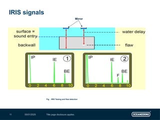
IRIS signals
Fig : IRIS Testing and flaw detection
Mirror
12.
05/01/2025 Title pagedisclosure applies.
12
• Remote field testing is a nondestructive testing method performed on
ferritic materials, which uses alternating current to induce an
electromagnetic field. Electric coils are then used to detect flaws and
measure material thickness in the part being inspected.
• The RFT probe has widely spaced coils to pick up the through-
transmission field. The typical ECT probe has coils or coil sets that create
a field and measure the response within a small area, close to the object
being tested.
• Advantages
1. Suitable for ferromagnetic materials
2. Equal sensitivity at the inner and outer surfaces
3. Highly sensitive to wall thickness variations
4. Can be used with lesser fill factors than ECT
• Link
RFT Technology
13.
05/01/2025 Title pagedisclosure applies.
13
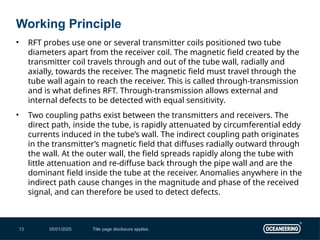
• RFT probes use one or several transmitter coils positioned two tube
diameters apart from the receiver coil. The magnetic field created by the
transmitter coil travels through and out of the tube wall, radially and
axially, towards the receiver. The magnetic field must travel through the
tube wall again to reach the receiver. This is called through-transmission
and is what defines RFT. Through-transmission allows external and
internal defects to be detected with equal sensitivity.
• Two coupling paths exist between the transmitters and receivers. The
direct path, inside the tube, is rapidly attenuated by circumferential eddy
currents induced in the tube’s wall. The indirect coupling path originates
in the transmitter’s magnetic field that diffuses radially outward through
the wall. At the outer wall, the field spreads rapidly along the tube with
little attenuation and re-diffuse back through the pipe wall and are the
dominant field inside the tube at the receiver. Anomalies anywhere in the
indirect path cause changes in the magnitude and phase of the received
signal, and can therefore be used to detect defects.
Working Principle
14.
05/01/2025 Title pagedisclosure applies.
14
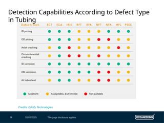
Detection Capabilities According to Defect Type
in Tubing
Credits: Eddify Technologies
15.
05/01/2025 Title pagedisclosure applies.
15
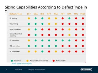
Sizing Capabilities According to Defect Type in
Tubing
Credits: Eddify Technologies
16.
05/01/2025 Title pagedisclosure applies.
16
Suitability According to Tubing Material
Credits: Eddify Technologies