EDR Group of Industries training report
•
1 like•365 views

EDR Group of Industries established in the year 1968 is dedicating to manufacturing of mechanical Seals and selling Systems, Centrifugal Pumps and Investment Castings.

Recommended
Recommended
More Related Content
Similar to EDR Group of Industries training report
Similar to EDR Group of Industries training report (20)
More from aman1312
More from aman1312 (20)
Recently uploaded
Recently uploaded (20)
EDR Group of Industries training report
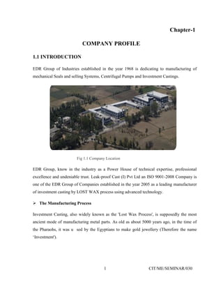
- 1. 1 CIT/ME/SEMINAR/030 Chapter-1 COMPANY PROFILE 1.1 INTRODUCTION EDR Group of Industries established in the year 1968 is dedicating to manufacturing of mechanical Seals and selling Systems, Centrifugal Pumps and Investment Castings. Fig 1.1 Company Location EDR Group, know in the industry as a Power House of technical expertise, professional excellence and undeniable trust. Leak-proof Cast (I) Pvt Ltd an ISO 9001-2008 Company is one of the EDR Group of Companies established in the year 2005 as a leading manufacturer of investment casting by LOST WAX process using advanced technology. The Manufacturing Process Investment Casting, also widely known as the 'Lost Wax Process', is supposedly the most ancient mode of manufacturing metal parts. As old as about 5000 years ago, in the time of the Pharaohs, it was u sed by the Egyptians to make gold jewellery (Therefore the name ‘Investment').
- 2. 2 CIT/ME/SEMINAR/030 1.2 GROUP OF COMPANIES A. Leak-Proof Engineering (I) Pvt. Ltd. (An ISO 9001-2008 Company) Established in the year 1973, Leak-Proof Engineering is pioneer in the field of manufacturing engineered mechanical seals and is one of the largest indigenous seal manufacturers in India. The company has constantly endeavored to upgrade the sealing and application engineering technology to device perfect sealing solution for all services. Today, with state of the art manufacturing facility, the company is a name to reckon with and has most satisfied clientele in the country and outside, both in terms of quality and service. B. Leak-Proof Pumps (I) Pvt. Ltd Established in the year 1989, Raje-Dia Pumps is a leading manufacturer of non-metallic centrifugal pumps in India. The product range includes PVDF, FEP & PFA lined centrifugal pumps, solid injection molded polypropylene pumps, magnetic drive pumps, metallic pumps and lined valves. The application range covers highly corrosive acids, alkalis, solvents and other corrosive fluids used in chemical process, petrochemical, fertilizer, refinery, power generation, food processing, oil extraction, bulk drug manufacturing, effluent treatment, steel and similar core industrial sectors. C. Leak-Proof Cast (I) Pvt. Ltd. (An ISO 9001-2008 Company) EDR Group of Industries established in the year 1968 is dedicating to manufacturing of mechanical Seals and selling Systems, Centrifugal Pumps and Investment Castings. EDR Group, know in the industry as a Power House of technical exprties, professional excellence and undeniable trust. Leak-proof Cast (I) Pvt Ltd an ISO 9001-2008 company is one of the EDR Group of Companies established in the year 2005 as a leading manufacturer of investment Casting by LOST WAX process using advanced technology.
- 3. 3 CIT/ME/SEMINAR/030 D. Leak-Proof Steel Plant Projects Pvt. Ltd. Leak-Proof Steel Plant Projects Pvt. Ltd. is established in the year 2010 The Company is engaged in the business of design, erection and commissioning of flat steel processing lines of all types on turnkey basis. Consultations for cost effective and energy efficient designs, optimizing production, reduction of power, acid recovery system, etc. are also offered. Latest additions to our line of activities are: • Environment eco friendly steel pickling lines without use of acid in association with The Material Works Limited, USA. • LIBS sensors for online molten metal composition check with laser sensors in association with Tecnar, Canada. • Spent acid recovery system in association with Beta control, Inc. USA. E. Leak Proof Auto Parts We are also pleased to introduce Allied Engineering as one of the part of EDR Group of the company since 2012 with the new name Leak Proof Auto Parts. Leak Proof Auto Parts is a manufacturing company specializing of auto body parts like Maruti Suzuki, Mahindra, Toyota, Tata, Ashok Leyland, and other components. Since 1992. With our extensive knowledge and experience of international business of automotive and engineering parts and in-depth understanding of clients requirements. We help accelerate the achievement of strategic sourcing and purchase objectives of overseas buyers enabling them to extract consistent quality and timely deliveries from all over India.
- 4. 4 CIT/ME/SEMINAR/030 1.3 STAFF WEALFARE The relationship between the company and employees is comparatively good. Staff member works with their full efficiency and try to give their maximum for the progress and welfare of the staff. The company gives good canteen facility which runs on the contract basis. Company provides tea snacks lunch and dinner to the staff and workers at subsidized rate. The company has setup water coolers with aqua guard in all the departments which provides cool and clean water to the staff. Company gives good salary, yearly increment and bonus to the employees. Company runs good credit society of the staff and workers jointly. This society also gives the loans to employees. Company gives sweets and dress to the workers on diwali. Company also organizes sports activities on dashera like cricket, volleyball long jump etc. between all departments and give prizes to the winners. Company pays travel allowance and leave with pay to all staff member. It also pays the medical allowance to the worker. The company celebrates the joy of each ones birthday by gift. 1.4 VARIOUS DEPARTMENT OF THE COMPANY Personal Department Purchase Department Sales Department Marketing Department R & D Department EDC Department Assembly Department Machine and Die Department Testing Department Quality Department
- 5. 5 CIT/ME/SEMINAR/030 Account & Finance Department Maintenance Department Store and Inspection department Planning Department Electrical Department
- 6. 6 CIT/ME/SEMINAR/030 Chapter-2 CENTRIFUGAL PUMP 1.1 INTRODUCTION Fig 2.1 Centrifugal pump A centrifugal pump is a Roto dynamic pump that uses a rotating impeller to increase the pressure of a fluid. Centrifugal pumps are commonly used to move liquids through a piping system. The fluid enters the pump impeller along or near to the rotating axis and is accelerated by the impeller, flowing radially outward into a diffuser or volute chamber (casing), from where it exits into the downstream piping system. Centrifugal pumps are used for large discharge through smaller heads. 2.1 HISTORY According to Reti, the Brazilian soldier and historian of science, the first machine thatcould be characterized as a centrifugal pump was a mud lifting machine which appeared as early as 1475 in a treatise by the Italian Renaissance engineer Francesco di Giorgio Martini.[1] True centrifugal pumps were not developed until the late 17th century, when Denis Papin made one with straight vanes. The curved vane was introduced byBritish inventor John Appold in 1851.
- 7. 7 CIT/ME/SEMINAR/030 2.3 HOW IT WORKS ? Like most pumps, a centrifugal pumps converts mechanical energy from a motor to energy of a moving fluid; some of the energy goes into kinetic energy of fluid motion, and some into potential energy, represented by a fluid pressure or by lifting the fluid. Against gravity toa higher level. The transfer of energy from the mechanical rotation of the impeller tothe motion and pressure of the fluid is usually described in terms ofCentrifugal force, especially in older sources written before the modern concept of centrifugal force as a fictitious force in a rotating reference frame was well articulated. The concept of centrifugal force is not actually required to describe the action of the centrifugal pump. In the modern centrifugal pump, most of the energy conversion is dueto the outward force that curved impeller blades impart on the fluid. Invariably, some of the energy also pushes the fluid into a circular motion, and this circular motion can also convey some energy and increase the pressure at the outlet. Fig 2.2 Internal part of centrifugal pump
- 8. 8 CIT/ME/SEMINAR/030 To arrive by a simpler method than that just given at a general idea of the mode of action of the exterior whirlpool in improving the efficiency of the centrifugal pump, it is only necessary to consider that the mass of water revolving in the whirlpool chamber, round the circumference of the wheel, must necessarily exert a centrifugal force, and that this centrifugal force may readily be supposed to add itself to the outward force generated within the wheel; or, in other words, to go to increase the pumping power of the wheel. The outward force generated within the wheel is to be understood as being produced entirely by the medium of centrifugal force if the vanes of the wheel be straight and radial; but if they be curved, as is more commonly the case, the outward force is partly produced through the medium of centrifugal force, and partly applied by the vanes to the water as a radial component of the oblique pressure, which, in consequence of their obliquity to the radius, they apply to the water as it moves outwards along them. On this subject it is well to observe that while the quantity of water made to pass through a given pump with curved vanes is perfectly variable at pleasure, the smaller the quantity becomes the more nearly will the force generated within the wheel for impelling the water outwards become purely centrifugal force, and the more nearly will the pump become what the name ordinarily given to it would seem to indicate—a purely centrifugal pump. When, however, a centrifugal putnp with vanes curved backwards in such forms as are ordinarily used in well-constructed examples of the machine, is driven at a speed considerably above that requisite merely to overcome the pressure of the water, and cause lifting orpropulsion to commence, the radial component of the force applied to the water by the vanes will become considerable, and the water leaving the circumference of the wheel will have a velocity less than that of the circumference of the wheel in a degree having some real importance iu practice. The statement "the mass of water ... must necessarily exert a centrifugal force" is interpretable in terms of the reactive centrifugal force—the force is not an outward force on the water, but rather an outward force exerting by the water, on the pump housing (the volute) and on the water in the outlet pipe. The outlet pressure is a reflection of the pressure that applies the centripetal force that curves the path of the water to move circularly inside the pump (in the space just outside the impeller, the
- 9. 9 CIT/ME/SEMINAR/030 exterior whirlpool as this author calls it). On the other hand, the statement that the "outward force generated within the wheel is to be understood as being produced entirely by the medium of centrifugal force" is best understood in terms of centrifugal force as a fictional force in the frame of reference of the rotating impeller; the actual forces on the water are inward, or centripetal, since that's the direction of force need to make the water move in circles. This force is supplied by a pressure gradient that is set up by the rotation, where the pressure at the outside, at the wall of the volute, can be taken as a reactive centrifugal force. This is typical of 19th and early 20th century writing, to mix these conceptions of centrifugal force in informal descriptions of effects such as that in the centrifugal pump. Fig 2.3 Side view part of Centrifugal pump Differing conceptions and explanations of how a centrifugal pump works have long engendered controversy and animadversion. For example, the American Expert Commission sent to the Vienna Exposition in 1873 issued a report that included observations that "they are misnamed centrifugal, because they do not operate by centrifugal force at all; they operate by pressure the same as a turbine water wheel; when people understand their method of operating we may expect much improvement." John Richards, editor of the San Francisco-based journal Industry, in his in-depth essay on centrifugal pumps, which also downplayed the significance of centrifugal force in the working of the pump, remarked. This extraordinary report stands printed in a Government publication, signed by men who were, or are, eminent in mechanics, and we can only deplore the stupidity, as well as presumption of the commission who thus disposed of a subject that
- 10. 10 CIT/ME/SEMINAR/030 had twenty years before been carefully investigated by such men as Sir John Rennie, Professor Cowper, Mr. Whitelaw, Dr. James Black, Professor Rankine, and many others. The most astonishing part is, however, that this report was passed and signed by men who we can hardly suppose would fail to perceive its absurdity. Modern sources say things like that the fluid "flows radially under centrifugal force", or "centrifugal force flings the liquid outward" Others counter that "there is no force at all, and a great deal of confused thinking." Some are more careful, attributing the outward force to the impeller, not to centrifugal force: "the impellers throw the water to the outside of the impeller case. This centrifugal action is what creates the pressure..." Even serious texts that explain the working of the pump without mention of centrifugal force introduce the pump as one in which "the mechanical energy is converted, into pressure energy by means of centrifugal force acting on the fluid." 2.4 VERTICAL CENTRIFUGAL PUMPS Vertical centrifugal pumps are also referred to as cantilever pumps. They utilize a unique shaft and bearing support configuration that allows the volute to hang in the sump while the bearings are outside of the sump. This style of pump uses no stuffing box to seal the shaft but instead utilizes a "throttle Bushing". A common application for this style of pump is in a parts washer. 2.5 MULTI-STAGE CENTRIFUGAL PUMPS A centrifugal pump containing two or more impellers is called a multistage centrifugal pump. The impellers may be mounted on the same shaft or on different shafts. If we need higher pressure at the outlet we can connect impellers in series. If we need a higher flow output we can connect impellers in parallel. All energy added to the fluid comes from the power of the electric or other motor force driving the impeller. 2.6 EFFICIENCY OF LARGE PUMPS Unless carefully designed, installed and monitored, pumps will be, or will become inefficient, wasting a lot of energy. Pumps need to be regularly tested to determine efficiency.
- 11. 11 CIT/ME/SEMINAR/030 2.7 ENERGY USAGE The energy usage in a pumping installation is determined by the flow required, the height lifted and the length and friction characteristics of the pipeline. The power required to drive a pump ( ), is a defined simply using SI unit by: 2.8 SINGLE STAGE RADIAL FLOW CENTRIFUGAL PUMP Where: is the input power required (W) is the fluid density (kg/m3) is the standard acceleration of gravity (9.80665 m/s2) is the energy Head added to the flow (m) is the flow rate (m3/s) is the efficiency of the pump plant as a decimal The head added by the pump ( ) is a sum of the static lift, the head loss due to friction and any losses due to valves or pipe bends all expressed in metres of fluid. Power is more commonly expressed as kilowatts (103 W) or horsepower (multiply kilowatts by 0.746). The value for the pump efficiency may be stated for the pump itself or as a combined efficiency of the pump and motor system. The energy usage is determined by multiplying the power requirement by the length of time the pump is operating. 2.9 PROBLEMS OF CENTRIFUGAL PUMPS • Cavitation—the NPSH of the system is too low for the selected pump • Wear of the Impeller—can be worsened by suspended solids • Corrosion inside the pump caused by the fluid properties • Overheating due to low flow • Leakage along rotating shaft
- 12. 12 CIT/ME/SEMINAR/030 • Lack of prime—centrifugal pumps must be filled (with the fluid to be pumped) in order to operate • Surge Fig 2.4 Surge 2.10 CENTRIFUGAL PUMPS FOR SOLID CONTROL An oilfield solids control system needs many centrifugal pumps to sit on or in mud tanks. The types of centrifugal pumps used are sand pumps, submersible slurry pumps, shear pumps, and charging pumps. They are defined for their different functions, but their working principle is the same. 2.11 MAGNECTICALLY COUPLED PUMPS Small centrifugal pumps (e.g. for garden fountains) may be magnetically coupled to avoid leakage of water into the motor. The motor drives a rotor carrying a pair of permanent magnets and these drag round a second pair of permanent magnets attached to the pump impeller. There is no direct connection between the motor shaft and the impeller so no gland is needed and, unless the casing is broken, there is no risk of leakage.
- 13. 13 CIT/ME/SEMINAR/030 2.12 PRIMING Most centrifugal pumps are not self-priming. In other words, the pump casing must be filled with liquid before the pump is started, or the pump will not be able to function. If the pump casing becomes filled with vapors or gases, the pump impeller becomes gas-bound and incapable of pumping. To ensure that a centrifugal pump remains primed and does not become gas-bound, most centrifugal pumps are located below the level of the source from which the pump is to take its suction. The same effect can be gained by supplying liquid to the pump suction under pressure supplied by another pump placed in the suction line.
- 14. 14 CIT/ME/SEMINAR/030 Chapter-3 ULTRA CAST PVT. LTD. 3.1 INTRODUCTION Fig 3.1 Company out look
- 15. 15 CIT/ME/SEMINAR/030 3.2 LAY OUT OF CAST 3.3 CASTING PROCESS Casting is a manufacturing process by which a liquid material is usually poured into a mold, which contains a hollow cavity of the desired shape, and then allowed to solidify. The solidified part is also known as a casting, which is ejected or broken out of the mold to complete the process. Casting materials are usually metals or various cold setting materials that cure after mixing two or more components together; examples are epoxy, concrete, ASSEMBLY WAX ROOM FETTLING MELTING DEWAXING DRYING ROOMCOATING ROOM
- 16. 16 CIT/ME/SEMINAR/030 plaster and clay. Casting is most often used for making complex shapes that would be otherwise difficult or uneconomical to make by other methods. Casting is a 6000 year old process. The oldest surviving casting is a copper frog from 3200 BC. 3.3.1 WAX INJECTION WAX INJECTION IS FIRST STEP OF THE INVESTMENT CASTING PROCESS. It is therefore an essential step,as many of the defects created in the wax can be reproduced in the final casting.if they are not detected. This paper will present the models set up and experimentation carried out to validate these models. Fig 3.2 WAX INJECTION
- 17. 17 CIT/ME/SEMINAR/030 3.3.2 WAX MOULD Model-making. An artist or mold-maker creates an original model from wax, clay, or another material. Wax and oil-based clay are often preferred because these materials retain their softness. Mold making. A mold is made of the original model or sculpture. The rigid outer molds contain the softer inner mold, which is the exact negative of the original model. Inner molds are usually made of latex, polyurethane rubber or silicone, which is supported by the outer mold. The outer mold can be made from plaster, but can also be made of fiberglass or other materials. Most molds are made of at least two pieces, and a shimwith keys is placed between the parts during construction so that the mold can be put back together accurately. If there are long, thin pieces extending out of the model, they are often cut off of the original and molded separately. Sometimes many molds are needed to recreate the original model, especially for large models. Wax. Once the mold is finished, molten wax is poured into it and swished around until an even coating, usually about 1 ⁄8 inch (3 mm) thick, covers the inner surface of the mold. This is repeated until the desired thickness is reached. Another method is to fill the entire mold with molten wax and let it cool until a desired thickness has set on the surface of the mold. After this the rest of the wax is poured out again, the mold is turned upside down and the wax layer is left to cool and harden. With this method it is more difficult to control the overall thickness of the wax layer. Removal of wax. This hollow wax copy of the original model is removed from the mold. The model-maker may reuse the mold to make multiple copies, limited only by the durability of the mold.
- 18. 18 CIT/ME/SEMINAR/030 Fig. 3.3 WAX MOULDS 3.3.3 ASSEMBLY Fig. 3.4 ASSEMBLY
- 19. 19 CIT/ME/SEMINAR/030 3.3.4 COATING A coating is a covering that is applied to the surface of an object, usually referred to as the substrate. In many cases coatings are applied to improve surface properties of the substrate, such as appearance, adhesion, wet ability, corrosion resistance, wear resistance, and scratch resistance. Some new coatings formulated using nanotechnology promise to create long-term surface protection.[1] In other cases, in particular in printing processes and semiconductor device fabrication (where the substrate is a wafer), the coating forms an essential part of the finished product. Coating and printing processes involve the application of a thin film of functional material to a substrate, such as paper, fabric, film, foil, or sheet stock. This article discusses what is frequently termed "roll-to-roll" or "web-based" coating. A roll of substrate, when wound through the coating machine, is typically called a web. Coatings may be applied as liquids, gases or solids. Coatings can be measured and tested for proper opacity and film thickness by using a drawdown card. Fig. 3.5 COATING
- 20. 20 CIT/ME/SEMINAR/030 3.3.5 DEWAXING Fig. 3.6 DEWAXING Removing wax from a material or object; a process used to separate solid hydrocarbons from petroleum. Removal of the wax from a material or a surface. Method is also used in separation of solid hydrocarbons from petroleum. 3.3.6 MONITORING TEMPERATURE Fig 3.7 MONITORING TEMPERATURE
- 21. 21 CIT/ME/SEMINAR/030 3.3.7 SPECTROMETER A spectrometer (spectrophotometer, spectrograph or spectroscope) is an instrument used to measure properties of light over a specific portion of the electromagnetic spectrum, typically used in spectroscopic analysis to identify materials.[1] The variable measured is most often the light's intensity but could also, for instance, be the polarization state. The independent variable is usually the wavelength of the light or a unit directly proportional to the photon energy, such as wave number or electron volts, which has a reciprocal relationship to wavelength. A spectrometer is used in spectroscopy for producing spectral lines and measuring their wavelengths and intensities. Spectrometer is a term that is applied to instruments that operate over a very wide range of wavelengths, from gamma rays and X- rays into the far infrared. If the instrument is designed to measure the spectrum in absolute units absolute units rather than relative units, then it is typically called a spectrophotometer. The majority of spectrophotometers are used in spectral regions near the visible spectrum. Fig 3.8 SPECTROMETER
- 22. 22 CIT/ME/SEMINAR/030 3.3.8 MELTING Melting, or fusion, is a physical process that results in the phase transition of a substance from a solid to a liquid. The internal energy of a substance is increased, typically by the application of heat or pressure, resulting in a rise of its temperature to the melting point, at which the ordering of ionic or molecular entities in the solid breaks down to a less ordered state and the solid liquefies. An object that has melted completely is molten. Substances in the molten state generally have reduced viscosity with elevated temperature; an exception to this maxim is the element sulfur, whose viscosity increases to a point due to polymerization and then decreases with higher temperatures in its molten state. Some organic compounds melt through mesophases, states of partial order between solid and liquid. Fig 3.9 MELTING DEPARTMENT
- 23. 23 CIT/ME/SEMINAR/030 To Solid Liquid Gas Plasma From Solid Solid-solid transformation Melting / fusion Sublimation — Liquid Freezing — Boiling / evaporation — Gas Deposition Condensation — Ionization Plasma — — Recombination / deionization — Fig 3.10 SHELL AFTER METAL POURING
- 24. 24 CIT/ME/SEMINAR/030 3.3.9 Fettling The removal of feeders and excess material from a casting - is the first stage of finishing a casting. The metal removal is often achieved using manual cutting or grinding. However, more emphasis is being placed on automatic fettling, whereby the casting is placed in a machine programmed to remove materials from specific areas. The method of fettling must be taken into account at the initial casting design stage, so that the process is fast and efficient. Fig 3.11 FETTLING DEPARTMENT Fig 3.12 SAND BLASTING
- 25. 25 CIT/ME/SEMINAR/030 Fig 3.13 SHOT BLASTING Fig 3.14 PICKLING 3.3.10 Blasting Abrasive particles, such as sand, grit or steel shot, are propelled at high velocity to impact the casting surface to remove surface contaminants. It can also be used to provide a uniform surface finish to castings. Propulsion of the abrasive particles is usually achieved using a centrifuge or compressed air nozzles. 3.3.11 PICKLING (METAL) Pickling is a metal surface treatment used to remove impurities, such as stains, inorganic contaminants, rust or scale from ferrous metals, copper, and aluminum alloys. A solution called pickle liquor, which contains strong acids, is used to remove the surface impurities. It is commonly used to decaled or clean steel in various steelmaking processes.
- 26. 26 CIT/ME/SEMINAR/030 Chapter-4 QUALITY ASSURANCE 4.1 INTRODUCTION Quality assurance (QA) refers to the engineering activities implemented in a quality system so that requirements for a product or service will be fulfilled.[1] It is the systematic measurement, comparison with a standard, monitoring of processes and an associated feedback loop that confers error prevention.[2] This can be contrasted with quality control, which is focused on process outputs. Two principles included in QA are: "Fit for purpose", the product should be suitable for the intended purpose; and "Right first time", mistakes should be eliminated. QA includes management of the quality of raw materials, assemblies, products and components, services related to production, and management, production and inspection processes. Suitable quality is determined by product users, clients or customers, not by society in general. It is not related to cost and adjectives or descriptors such "high" and "poor" are not applicable. For example, a low priced product may be viewed as having high quality because it is disposable where another may be viewed as having poor quality because it is not disposable.
- 27. 27 CIT/ME/SEMINAR/030 Fig 4.1 FINISHED CASTINGS
- 28. 28 CIT/ME/SEMINAR/030 4.2 WORKING PROCESS PLANNING RECEIVE ORDER ACKNOWLEADEMENT (O.A) AND BILL OF MATERIAL (B.M.) REVIEW CHECK/VERIFY/ALL O.A SPECIFICATIONS PUMP MODEL PUMP PERFORMANCE SPECIFICATION SEAL TYPE BASE FRAME, COUPLING GUARD ETC. REVIEW CHEK VERIFY B.M THROUGHLY OFFER O.A AND B.M TO STORES TO CONFORM AVAILABILITY OF RAW MATERIAL AND FINISH COMPONENT. ( 1 DAYS ) O.A AND B.M OFFERED BACK FROM STORES WITH REMARK AVAILABILITY/NONAVAILBILITY OF MATERIAL. GENERATE JOB CARD F-PDN/01B, OFFER TO STORES. ( 1 DAY ) IN CASE NON AVAILABILITY OF MATERIAL GENRATE PLANNING INDENT SUBMIT TO PURCHASE. ALL ORDERS DETAIL ENTERIES MAINTAINING IN EXCEL SHEET AND ERP SYSTEM. GENERATE WEEKLY PRODUCTION SCHEDULE. PLANNING TO MONITOR IMPELLER DIAMETER / HEAD / PUMP CAPACITY AS PER REQUIREMEN. ACCORDINGLY WEEKLY SCHEDULE MONITER MANUFACTURING STATUS AT ALL STAGES CASTING (PRODUCTION) / Q.A / ASSEMBLY / MOLDING / TESTING / PAINTING / PACKING / DISPATCH. MAINTAIN ALL ISO 9001-2008 / RETENTION PERIOD AS PER FREQUENCY.
- 29. 29 CIT/ME/SEMINAR/030 Fig 4.2 ASSEMBLY & PACKING 4.3 PACKANGING AND LABELING Packaging is the science, art, and technology of enclosing or protecting products for distribution, storage, sale, and use. Packaging also refers to the process of design, evaluation, and production of packages. Packaging can be described as a coordinated system of preparing goods for transport, warehousing, logistics, sale, and end use. Packaging contains, protects, preserves, transports, informs, and sells.[1] In many countries it is fully integrated into government, business, institutional, industrial, and personal use. Package labeling (American English) or labeling (British English) is any written, electronic, or graphic communications on the packaging or on a separate but associated label. 4.4 PURPOSES OF PACKAGING AND PACKAGE LABELS Diced pork in tray and film overwrap. Label indicates net weight, composition, preparation, etc. The Union Flag, British Farm Standard tractor logo, and British Meat Quality Standard logo are also present. Packaging and package labeling have several objectives:
- 30. 30 CIT/ME/SEMINAR/030 Physical protection – The objects enclosed in the package may require protection from, among other things, mechanical shock, vibration, electrostatic discharge, compression, temperature,] etc. Barrier protection – A barrier from oxygen, water vapor, dust, etc., is often required. Permeation is a critical factor in design. Some packages contain desiccants or Oxygen absorbers to help extend shelf life. Modified atmospheres or controlled atmospheres are also maintained in some food packages. Keeping the contents clean, fresh, sterile and safe for the intended shelf life is a primary function. Containment or agglomeration – Small objects are typically grouped together in one package for reasons of efficiency. For example, a single box of 1000 pencils requires less physical handling than 1000 single pencils. Liquids, powders, and granular materials need containment. Information transmission – Packages and labels communicate how to use, transport, recycle, or dispose of the package or product. With pharmaceuticals, food, medical, and chemical products, some types of information are required by governments. Some packages and labels also are used for track and trace purposes. Marketing – The packaging and labels can be used by marketers to encourage potential buyers to purchase the product. Package graphic design and physical design have been important and constantly evolving phenomenon for several decades. Marketing communications and graphic design are applied to the surface of the package and (in many cases) the point of sale display.
- 31. 31 CIT/ME/SEMINAR/030 Fig. 4.3 QUALITY ASSURANCE Fig 4.4 DIFFERENT TYPES OF TESTING METHODS
- 32. 32 CIT/ME/SEMINAR/030 CONCLUSION So this is all about the learning’s at EDR INDUSTRIAL ESTATE within 45 DAYS. To do my summer training in EDR INDUSTRIAL was a phenomenal learning experience for me. This one month was a joy ride for me in the mechanical field, and now on completion of my training I can say that I have gained very sound knowledge in mechanical field.
- 33. 33 CIT/ME/SEMINAR/030 SAFETY MEASURES Always wear helmet for protection of head. Always wear spectacles for protection of dust Wear dust mask to protect dust from entering nose. Wear gloves while doing oily work. Always wear shoes to protect our self from electric shock.