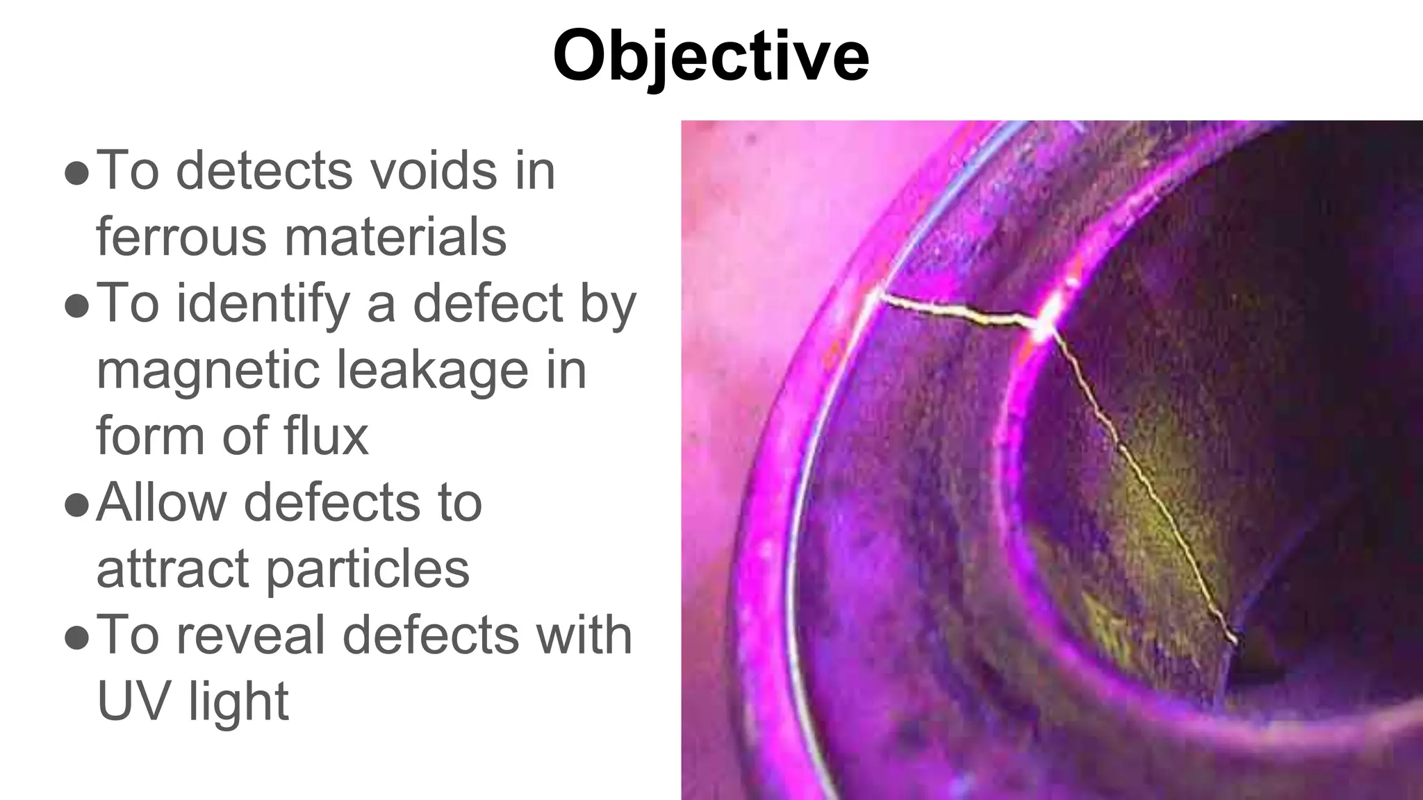
Magnetic Particle Inspection
Team 6
Allison Lock
Cathlene Farnelli
Steve Kreeley
Objective
●To detects voids in
ferrous materials
●To identify a defect by
magnetic leakage in
form of flux
●Allow defects to
attract particles
●To reveal defects with
UV light
Theory Behind Leakage
●Ferrous, flawless specimen:
●Ferrous, cracked specimen:
Method & Approach
●Magnetic field
induced in material
●Apply coating of
fluorescent
magnetic particle
solution
●Shine object with
UV light
Method & Approach (cont.)
●Direct Current or
Magnetic Flux Flow
methods
●Digital Imaging and
Filtering used
●Canny algorithm used
to de-noise and detect
edges
Method & Approach (cont.)
●Similar to Dye Particle Inspection (DPI)
●Used for Ferromagnetic Objects
●Detects Surface or Near-Surface Flaws
●Current must hit Long Dimension at Right Angle
Direct Current Method
●Current sent
through Object
●Generates
Magnetic Field
●Identifies Defect.
Magnetic Flux Flow Method
●Flux induced in object
●Done by Permanent
Magnet or Current
from Coil or Conductor
Devices Used
●Field Indicators
●Hall Effect Meters
●Two most common
●Others include prods, portable coils, and conductive
cables
Field Indicators
●Iron Vane rotates and
deflects with Magnetic Field
●Analogous to Weather
Vane with Wind
●Iron Vane moves to rotate a
needle that turns a pointer
●Pointer indicates
measurement
Hall Effect Meters
●Also called Gauss or Tesla
Meters
●Provides Digital Output of
Magnetic Field Strength
●Current Passes through
Conductor inside Probe
●Probe placed in Magnetic Field
●Magnetic Lines oriented at
Right Angle with Long
Dimension
Real World Applications
●Bridges
●Underwater Utilities
●Pressure Vessels
●Boilers
● Surface defects
● Welded joints
● Components of pressure systems
○ Boilers, pressure vessels, locomotives, tanks
Method Application
LEFT: Weld Inspection, CENTER: Drive Shaft with Cracking, RIGHT: Crack in Steam Drum Seam.
Laboratory Example (Crankshaft)
●Crankshaft Rotates to get Complete View with UV
Light
●CCD Camera Captures Images
●PC Reads and Processes Images for Evaluation
Dry
● Common, relatively cheap
● Generally applied to
rougher surfaces
● Particle types
○ Elongated - align well
with magnetic fields
○ Rounded - move freely
across a surface
Magnetic Particles
Wet
● More expensive, accurate
● Painted or sprayed onto
surfaces
● Wet dye classifications
○ Light (UV or
fluorescent)
○ Removal type (water,
solvent, or emulsifier)
Sample Results
LEFT and CENTER: Image of pipe with and without magnetic particles showing cracks emanating from a hole. RIGHT:
Magnetic particle wet fluorescent indication of a crack in a bearing.
Method Assessment
Cons:
Time consuming evaluation
● Subjective based on user
experience and eyesight
● Problems with area changes,
textures
● Fluorescent lighting can be
damaging to the optic health of
workers
● Magnetic coagulation of dyes
Pros:
● Dry: common, relatively cheap
● Wet: more expensive, accurate
● Effective for detection, sizing
and location of surface and
near-surface flaws
Depiction of Magnetic Field and Particle
Coagulation Over a Crack with Parts of
Chain Both Inside and Outside of
Magnetic Field
Two-dimensional median filter - filtering
Reduces the complexity, integrity is kept (assuming high
resolution)
Image Processing Example Procedure
Gradient operator and a grey-scale transform - enhancing
Gradient operator required for following step, grey-scale
transform amplifies/suppresses
Image Processing Example Procedure
Canny Operator (wavelet-based) for edge detection -
segmentation
Wavelet-based: analyzes smaller window
Run through edge detection, then inverse in order to form
image with enhanced edges
Image Processing Example Procedure
Area filling - final image
All areas considered to be part of crack are highlighted
Image Processing Example Procedure
Sample Results: Image Processing
Figure 6: Images of the Recorded Data Throughout Processing (1) Raw Data
(2) Data After Median Filter (3) Data After Grey-Scale Transform (4) Data After
Wavelet-Based Canny Operator (5) Data After Filling (Final Image)
Pros:
● Further processes data without
human inspector’s input
● Less time and discrepancies
● Increasing the readability of results
● Can be done with original method or
as post-processing
● May in the future be utilized as
a fully automatic process
Method Assessment
Cons:
● More equipment required
● Results may need to be done as post-
processing, not in field
● More expensive, may require
inspection company to buy software
References
"Examples of Visible Dry Magnetic Particle Indications." NDT Education Resource Center. Collaboration for
Nondestructive Testing (Iowa State University), National Science Foundation, 2001. Web. 16 Nov. 2015.
"Examples of Fluorescent Wet Magnetic Particle Indications." NDT Education Resource Center. Collaboration for
Nondestructive Testing (Iowa State University), National Science Foundation, 2001. Web. 16 Nov. 2015.
"GV-02 Crack Detection: Machine Vision Magnetic Particle Inspection."Sonic Diagnostic. Sonic Diagnostic, 2010.
Web. 5 Dec. 2015.
Luo, Jianlan, Zhewen Tian, and Jintao Yang. "Fluorescent Magnetic Particle Inspection Device Based on Digital
Image Processing." Proceeding of the 11th World Congress on Intelligent Control and Automation (2014). Print.
"Manual for the Training Guidelines in Non-destructive Testing Techniques." Liquid Penetrant and Magnetic Particle Testing
at Level 2, 11 (2000): 5-6. Print.
Shelikhov, G. S. "The Effect of Coagulation of Magnetic Particles on the Detectability of Flaws in Magnetic-Powder
Inspection." Russian Journal of Nondestructive Testing. N.p., 6 Nov. 2004. Web. 26 Nov. 2015.
Worman, Jim. "Magnetic Particle Examination." The National Board of Boiler and Pressure Vessel Inspectors. N.p.,
2015. Web. 17 Nov. 2015.

Magnetic Particle Inspection

  • 1.
    Magnetic Particle Inspection Team6 Allison Lock Cathlene Farnelli Steve Kreeley
  • 2.
    Objective ●To detects voidsin ferrous materials ●To identify a defect by magnetic leakage in form of flux ●Allow defects to attract particles ●To reveal defects with UV light
  • 3.
    Theory Behind Leakage ●Ferrous,flawless specimen: ●Ferrous, cracked specimen:
  • 4.
    Method & Approach ●Magneticfield induced in material ●Apply coating of fluorescent magnetic particle solution ●Shine object with UV light
  • 5.
    Method & Approach(cont.) ●Direct Current or Magnetic Flux Flow methods ●Digital Imaging and Filtering used ●Canny algorithm used to de-noise and detect edges
  • 6.
    Method & Approach(cont.) ●Similar to Dye Particle Inspection (DPI) ●Used for Ferromagnetic Objects ●Detects Surface or Near-Surface Flaws ●Current must hit Long Dimension at Right Angle
  • 7.
    Direct Current Method ●Currentsent through Object ●Generates Magnetic Field ●Identifies Defect.
  • 8.
    Magnetic Flux FlowMethod ●Flux induced in object ●Done by Permanent Magnet or Current from Coil or Conductor
  • 9.
    Devices Used ●Field Indicators ●HallEffect Meters ●Two most common ●Others include prods, portable coils, and conductive cables
  • 10.
    Field Indicators ●Iron Vanerotates and deflects with Magnetic Field ●Analogous to Weather Vane with Wind ●Iron Vane moves to rotate a needle that turns a pointer ●Pointer indicates measurement
  • 11.
    Hall Effect Meters ●Alsocalled Gauss or Tesla Meters ●Provides Digital Output of Magnetic Field Strength ●Current Passes through Conductor inside Probe ●Probe placed in Magnetic Field ●Magnetic Lines oriented at Right Angle with Long Dimension
  • 12.
    Real World Applications ●Bridges ●UnderwaterUtilities ●Pressure Vessels ●Boilers
  • 13.
    ● Surface defects ●Welded joints ● Components of pressure systems ○ Boilers, pressure vessels, locomotives, tanks Method Application LEFT: Weld Inspection, CENTER: Drive Shaft with Cracking, RIGHT: Crack in Steam Drum Seam.
  • 14.
    Laboratory Example (Crankshaft) ●CrankshaftRotates to get Complete View with UV Light ●CCD Camera Captures Images ●PC Reads and Processes Images for Evaluation
  • 15.
    Dry ● Common, relativelycheap ● Generally applied to rougher surfaces ● Particle types ○ Elongated - align well with magnetic fields ○ Rounded - move freely across a surface Magnetic Particles Wet ● More expensive, accurate ● Painted or sprayed onto surfaces ● Wet dye classifications ○ Light (UV or fluorescent) ○ Removal type (water, solvent, or emulsifier)
  • 16.
    Sample Results LEFT andCENTER: Image of pipe with and without magnetic particles showing cracks emanating from a hole. RIGHT: Magnetic particle wet fluorescent indication of a crack in a bearing.
  • 17.
    Method Assessment Cons: Time consumingevaluation ● Subjective based on user experience and eyesight ● Problems with area changes, textures ● Fluorescent lighting can be damaging to the optic health of workers ● Magnetic coagulation of dyes Pros: ● Dry: common, relatively cheap ● Wet: more expensive, accurate ● Effective for detection, sizing and location of surface and near-surface flaws Depiction of Magnetic Field and Particle Coagulation Over a Crack with Parts of Chain Both Inside and Outside of Magnetic Field
  • 18.
    Two-dimensional median filter- filtering Reduces the complexity, integrity is kept (assuming high resolution) Image Processing Example Procedure
  • 19.
    Gradient operator anda grey-scale transform - enhancing Gradient operator required for following step, grey-scale transform amplifies/suppresses Image Processing Example Procedure
  • 20.
    Canny Operator (wavelet-based)for edge detection - segmentation Wavelet-based: analyzes smaller window Run through edge detection, then inverse in order to form image with enhanced edges Image Processing Example Procedure
  • 21.
    Area filling -final image All areas considered to be part of crack are highlighted Image Processing Example Procedure
  • 22.
    Sample Results: ImageProcessing Figure 6: Images of the Recorded Data Throughout Processing (1) Raw Data (2) Data After Median Filter (3) Data After Grey-Scale Transform (4) Data After Wavelet-Based Canny Operator (5) Data After Filling (Final Image)
  • 23.
    Pros: ● Further processesdata without human inspector’s input ● Less time and discrepancies ● Increasing the readability of results ● Can be done with original method or as post-processing ● May in the future be utilized as a fully automatic process Method Assessment Cons: ● More equipment required ● Results may need to be done as post- processing, not in field ● More expensive, may require inspection company to buy software
  • 24.
    References "Examples of VisibleDry Magnetic Particle Indications." NDT Education Resource Center. Collaboration for Nondestructive Testing (Iowa State University), National Science Foundation, 2001. Web. 16 Nov. 2015. "Examples of Fluorescent Wet Magnetic Particle Indications." NDT Education Resource Center. Collaboration for Nondestructive Testing (Iowa State University), National Science Foundation, 2001. Web. 16 Nov. 2015. "GV-02 Crack Detection: Machine Vision Magnetic Particle Inspection."Sonic Diagnostic. Sonic Diagnostic, 2010. Web. 5 Dec. 2015. Luo, Jianlan, Zhewen Tian, and Jintao Yang. "Fluorescent Magnetic Particle Inspection Device Based on Digital Image Processing." Proceeding of the 11th World Congress on Intelligent Control and Automation (2014). Print. "Manual for the Training Guidelines in Non-destructive Testing Techniques." Liquid Penetrant and Magnetic Particle Testing at Level 2, 11 (2000): 5-6. Print. Shelikhov, G. S. "The Effect of Coagulation of Magnetic Particles on the Detectability of Flaws in Magnetic-Powder Inspection." Russian Journal of Nondestructive Testing. N.p., 6 Nov. 2004. Web. 26 Nov. 2015. Worman, Jim. "Magnetic Particle Examination." The National Board of Boiler and Pressure Vessel Inspectors. N.p., 2015. Web. 17 Nov. 2015.