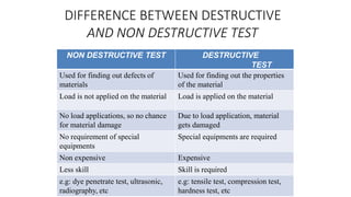
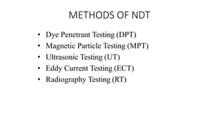
What is NDT?
• Nondestructive testing or non-
destructive testing (NDT) is a wide
group of analysis techniques used in
science and technology
industry to
evaluate
material,
component
the properties of
a or system
without
causing damage.
• The terms nondestructive examination
(NDE), nondestructive inspection (NDI),
and nondestructive evaluation (NDE)
are also commonly used to describe this
technology.
• Because NDT does not permanently alter
the article being inspected, it is a highly
valuable technique that can save both
money and time in product evaluation,
troubleshooting, and research.
NDT does not directly measure mechanical
properties but they are used to locate defects
or flaws in the component.
Flaws reduce useful life of component
resulting in premature failure even with a
sound design and proper selection of
materials.
To obtain high level of reliability , defect
should be absent or at minimum level.
 NDT is carried out periodically.
Replacement of component before its
premature failure to avoid dangerous results.
ADVANTAGES OF NDT
• The equipments are easy to handle
• Defects can be detected without damaging the
components
• Methods are quick and accurate
• Components can be sorted out on the basis of
electrical, magnetic or chemical properties
• Test results and other information can be
conveniently recorded on paper films, cassettes
and floppies
DIFFERENCE BETWEEN DESTRUCTIVE
AND NON DESTRUCTIVE TEST
NON DESTRUCTIVE TEST DESTRUCTIVE
TEST
Used for finding out defects of
materials
Used for finding out the properties
of the material
Load is not applied on the material Load is applied on the material
No load applications, so no chance
for material damage
Due to load application, material
gets damaged
No requirement of special
equipments
Special equipments are required
Non expensive Expensive
Less skill Skill is required
e.g: dye penetrate test, ultrasonic,
radiography, etc
e.g: tensile test, compression test,
hardness test, etc
METHODS OF NDT
• Dye Penetrant Testing (DPT)
• Magnetic Particle Testing (MPT)
• Ultrasonic Testing (UT)
• Eddy Current Testing (ECT)
• Radiography Testing (RT)
1.Dye Penetrant Inspection
Invisible cracks, porosity and other defects on
the surface of components easily detected by
this technique.
Components may be ferrous, nonferrous,
plastic, glass or ceramic.
 Procedure:-
1. Cleaning of surface.(Grease, oil, any
other material).
2. Drying of surface.
3. Applying dye-penetrant on clean and dry
surface. It is allowed to penetrate in surface
flaws.
i) Liquid Soluble Penetrant
ii) Fluroscent
4. Removing excess penetrant by soft or clean
cotton.
5. Applying developer on surface. This pulls out
dye from flaws and flaws are revealed by
colour of dye. Instead of developer, fine
developing powder or talc powder can be
sprinkled on the surface.
PROCESS FOR DPT
https://www.youtube.com/watch?v=bHTRmTQDZzg
Advantages of Dye Penetrant Inspecti
• This test can be applied to almost any type
of metals, nonmetals, magnetic or non
magnetic type.
• Simple to utilize and control.
• Results of test can be interpreted fastly.
• Cost of test is very less as it does not
require any instrument or electronic
display units.
• Sensitivity is greater than that of magnetic
particle testing.
Disadvantages of Dye Penetrant
Inspection
• Cleaningof componentsis must before
and after testing to avoid rusting
• Misleading results may be obtained in case
of components with surface films and
coatings
• Only surface defects can be detected
• Test is not applicable for powder
metallurgical components
MAGNETIC PARTICLE TESTING
• This method is suitable for the detection of
surface and near surface discontinuities in
magnetic material , mainly ferrite steel and
iron
• METHODS OF MPT
• Dry method
• Wet method
PRINCIPLE OF MPT
• In the first figure the magnetized metal has no crack and there
only two poles that is north pole and south pole.
• And in second figure the magnetized metal has a crack and at
the crack point there creates another north and south pole for
the magnetic flux leakage.
MPT Procedure
1. Cleaning Surface
2. Magnetization
3. Application of ferromagnetic
Powder
4. Observation and Inspection
5. Demagnetization
https://www.youtube.com/watch?v=sfjK1GZ2W9A
MPT IN GAS PIPE WELDING
Particles make a cluster at the welding joint for magnetic flux
leakage because of welding defects.
ADVANTAGES OF MPT
• Principally and relatively simple method
• Economical and easy to perform
• Portable for field testing
• Fast for production testing
• Reveal or disclose small surface flaws or
cracks which may be tight
LIMITATIONS OF MPT
• Material must be ferromagnetic
• Orientation and strength of magnetic field is
critical
• Detects surface and near-to-surface
discontinuities only
• Large currents are required
Principle-
1.Measure of time required by ultrasonic
vibrations to penetrate material of interest ,
reflect from opposite side or from internal
discontinuity and return to point from where
first introduced.
2.Behaviour of waves through cycle with
regard to time is recorded on CRO screen.
3.By observing this presence of defect and
their location can be detected.
Two types of Ultrasonic testing
method- i)Pulse –echo method
3.Ultrasonic Test/inspection
PULSE-ECHO METHOD
https://www.youtube.com/watch?v=DwYQilMGPFk
TRANSMISSION METHOD
ADVANTAGES OF ULTRASONIC TESTING
• Thickness and lengths up to 30 ft can be
tested
• Position, size and type of defect can be
determined
• Instant test results
• Portable
• Capable of being fully automated
• Access to only one side necessary
LIMITATIONS OF ULTRASONIC TESTING
• The operator can decide whether the test
piece is defective or not while the test is in
progress.
• Considerable degree of skill necessary to
obtain the fullest information from the test.
• Very thin sections can prove difficult.
ULTRASONIC MEASUREMENT
EDDY CURRENT TESTING(ECT)
• Used to detect surface flaws, to
measure thin walls from one surface
only
• To measure thin coating sand in some
applications to measure depth. This
method is applicable to electrically
conductive materials only
• In this method eddy currents are
produced in the product by bringing
it close to an alternating current
carrying coil.
• The main applications of the eddy
current technique are for the
detection of surface or subsurface
flaws, conductivity measurement and
coating thickness measurement.
https://www.youtube.com/watch?v=NILzyvEaiPE
APPLICATION OF ECT
• Crack Detection
• Corrosion Monitoring
• Material Thickness Measurements
• Coating Thickness Measurements
• Conductivity Measurements
ADVANTAGES OF ECT
• Sensitive to small cracks and other defects
• Detect surface and near surface defects
• Inspection gives immediate results
• Equipment is very portable
• Method can be used for much more than flaw
detection
• Inspects complex shapes and sizes of
conductive materials
LIMITATIONS OF ECT
• Only conductive materials can be inspected
• Skill and training required is more extensive
than other techniques
• Surface finish and roughness may interfere
• Depth of penetration is limited.
RADIOGRAPHY
• Radiography Testing (RT), or
industrial radiography is NDT
method of inspecting materials for
hidden flaws by using the ability of
short wavelength electromagnetic
radiation (high energy photons)to
penetrate various materials
• Radiographic Testing Method is
nothing but to take the shadow
picture of an object onto a film by
the passage of X-ray or Gamma ray
through it
• It is the same as the medical
radiography (X-ray). Only
difference in their wave length.
RADIOGRAPHY TESTING PROCESS
https://www.youtube.com/watch?v=7oR_l8nXdmo
DIFFERENCE BETWEEN X RAY AND GAMMA
RAY RADIOGRAPHY
X RAYS GAMMARAYS
Larger wavelength Shorter wavelength
Less penetration power High penetration power
Used for components having thickness
up to 62mm
Used for more thickness components
Only one component can be examined
at a time
Many components can be examined at
a time
Equipment is larger in size Equipment is smaller in size
More intensity and faster Less intensity and slower
RADIOGRAPHY
LIMITATIONS OF RADIOGRAPHY
• Possible health hazard
• Need to direct the beam accurately for two-
dimensional defects
• Film processing and viewing facilities are
necessary
• Not suitable for automation
• Not suitable for surface defects.
APPLICATION OF RADIOGRAPHY
• For detection of internal defects
• For detection of porosity, casting, lack of
fusion in welding, cracks
• For measurement of geometry variation
and thickness of components
RADIOGRAPHY
ULTRASONIC TESTING RADIOGRAPHY TESTING
Less flaw detection capabilities More flaw detection capabilities
Compared to radiography less
operational
safety is required
More operational safety is required as
the
radiations are harmful
Probe is used Probe is not used
Better accuracy and reliability Very fast method of testing
Operated manually Less or no manual work
Used for detection of internal defect,
measurement of conductivity and
crack depth
For detection of internal defects,
porosity, casting, lack of fusion in
welding, cracks, measurement of
geometry variation and thickness of
components
Ultrason
ic
testing
Radiograp
hy testing
Common Application of NDT
• Inspection of Raw Products
• Inspection Following Secondary
Processing
• In-Services Damage Inspection
Inspection of Raw Products
• Forgings,
• Castings,
• Extrusions,
• etc.
• Machining
• Welding
• Grinding
• Heat treating
• Plating
• etc.
Inspection Following
Secondary Processing
• Cracking
• Corrosion
• Erosion/Wear
• Heat Damage
• etc.
Inspection For
In-Service Damage
Power Plant Inspection
Probe
Signals produced by
various amounts of
corrosion thinning.
Periodically, power plants are
shutdown for inspection.
Inspectors feed eddy current probes
into heat exchanger tubes to check
for corrosion damage.
Pipe with damage
Wire Rope Inspection
Electromagnetic devices and
visual inspections are used to
find broken wires and other
damage to the wire rope that is
used in chairlifts, cranes and
other lifting devices.
Storage Tank Inspection
Robotic crawlers use
ultrasound to inspect
the walls of large above
ground tanks for signs
of thinning due to
corrosion.
Cameras on long
articulating arms
are used to
inspect
underground
storage tanks for
damage.
Aircraft Inspection
• Nondestructive testing is used
extensively during the
manufacturing of aircraft.
• NDT is also used to find cracks
and corrosion damage during
operation of the aircraft.
• A fatigue crack that started at the
site of a lightning strike is shown
below.
Jet Engine Inspection
• Aircraft engines are overhauled after
being in service for a period of time.
• They are completely disassembled,
cleaned, inspected and then
reassembled.
• Fluorescent penetrant inspection is
used to check many of the parts for
cracking.
Sioux City, Iowa, July 19, 1989
A defect that went
undetected in an
engine disk was
responsible for the
crash of United Flight
232.
Crash of United Flight 232
Pressure Vessel Inspection
The failure of a pressure vessel can
result in the rapid release of a large
amount of energy. To protect against
this dangerous event, the tanks are
inspected using radiography and
ultrasonic testing.
Rail Inspection
Special cars are used to inspect
thousands of miles of rail to
find cracks that could lead to a
derailment.
Bridge Inspection
• The US has 578,000
highway bridges.
• Corrosion, cracking and
other damage can all affect
a bridge’s performance.
• The collapse of the Silver
Bridge in 1967 resulted in
loss of 47 lives.
• Bridges get a visual
inspection about every 2
years.
• Some bridges are fitted with
acoustic emission sensors
that “listen” for sounds of
cracks growing.
NDT is used to inspect pipelines to
prevent leaks that could damage the
environment. Visual inspection,
radiography and electromagnetic testing
are some of the NDT methods used.
Remote visual inspection using a
robotic crawler.
Radiography of weld joints.
Magnetic flux leakage inspection. This
device, known as a pig, is placed in the
pipeline and collects data on the
condition of the pipe as it is pushed
along by whatever is being
transported.
Pipeline Inspection
Special Measurements
Boeing employees in Philadelphia were given the privilege of evaluating
the Liberty Bell for damage using NDT techniques. Eddy current methods
were used to measure the electrical conductivity of the Bell's bronze
casing at a various points to evaluate its uniformity.
CONCLUSION
• NDT is a new technology and system for
industrial inspection and testing
• Many developed countries uses this
technology because of its huge benefits
• Modern NDT methods will become just as an
important tool for risk based inspection
approaches and maintenance planning
• For this purpose every industry should have a
NDT division with NDT personnel
REFERENCES
• Material Science and Metallurgy for
Engineers by V D Kodgire and S V
Kodgire

ndt.pptx

  • 1.
    What is NDT? •Nondestructive testing or non- destructive testing (NDT) is a wide group of analysis techniques used in science and technology industry to evaluate material, component the properties of a or system without causing damage. • The terms nondestructive examination (NDE), nondestructive inspection (NDI), and nondestructive evaluation (NDE) are also commonly used to describe this technology.
  • 2.
    • Because NDTdoes not permanently alter the article being inspected, it is a highly valuable technique that can save both money and time in product evaluation, troubleshooting, and research.
  • 3.
    NDT does notdirectly measure mechanical properties but they are used to locate defects or flaws in the component. Flaws reduce useful life of component resulting in premature failure even with a sound design and proper selection of materials. To obtain high level of reliability , defect should be absent or at minimum level.  NDT is carried out periodically. Replacement of component before its premature failure to avoid dangerous results.
  • 4.
    ADVANTAGES OF NDT •The equipments are easy to handle • Defects can be detected without damaging the components • Methods are quick and accurate • Components can be sorted out on the basis of electrical, magnetic or chemical properties • Test results and other information can be conveniently recorded on paper films, cassettes and floppies
  • 5.
    DIFFERENCE BETWEEN DESTRUCTIVE ANDNON DESTRUCTIVE TEST NON DESTRUCTIVE TEST DESTRUCTIVE TEST Used for finding out defects of materials Used for finding out the properties of the material Load is not applied on the material Load is applied on the material No load applications, so no chance for material damage Due to load application, material gets damaged No requirement of special equipments Special equipments are required Non expensive Expensive Less skill Skill is required e.g: dye penetrate test, ultrasonic, radiography, etc e.g: tensile test, compression test, hardness test, etc
  • 6.
    METHODS OF NDT •Dye Penetrant Testing (DPT) • Magnetic Particle Testing (MPT) • Ultrasonic Testing (UT) • Eddy Current Testing (ECT) • Radiography Testing (RT)
  • 7.
    1.Dye Penetrant Inspection Invisiblecracks, porosity and other defects on the surface of components easily detected by this technique. Components may be ferrous, nonferrous, plastic, glass or ceramic.  Procedure:- 1. Cleaning of surface.(Grease, oil, any other material). 2. Drying of surface.
  • 8.
    3. Applying dye-penetranton clean and dry surface. It is allowed to penetrate in surface flaws. i) Liquid Soluble Penetrant ii) Fluroscent 4. Removing excess penetrant by soft or clean cotton. 5. Applying developer on surface. This pulls out dye from flaws and flaws are revealed by colour of dye. Instead of developer, fine developing powder or talc powder can be sprinkled on the surface.
  • 10.
  • 13.
    Advantages of DyePenetrant Inspecti • This test can be applied to almost any type of metals, nonmetals, magnetic or non magnetic type. • Simple to utilize and control. • Results of test can be interpreted fastly. • Cost of test is very less as it does not require any instrument or electronic display units. • Sensitivity is greater than that of magnetic particle testing.
  • 14.
    Disadvantages of DyePenetrant Inspection • Cleaningof componentsis must before and after testing to avoid rusting • Misleading results may be obtained in case of components with surface films and coatings • Only surface defects can be detected • Test is not applicable for powder metallurgical components
  • 15.
    MAGNETIC PARTICLE TESTING •This method is suitable for the detection of surface and near surface discontinuities in magnetic material , mainly ferrite steel and iron • METHODS OF MPT • Dry method • Wet method
  • 16.
    PRINCIPLE OF MPT •In the first figure the magnetized metal has no crack and there only two poles that is north pole and south pole. • And in second figure the magnetized metal has a crack and at the crack point there creates another north and south pole for the magnetic flux leakage.
  • 17.
    MPT Procedure 1. CleaningSurface 2. Magnetization 3. Application of ferromagnetic Powder 4. Observation and Inspection 5. Demagnetization https://www.youtube.com/watch?v=sfjK1GZ2W9A
  • 18.
    MPT IN GASPIPE WELDING Particles make a cluster at the welding joint for magnetic flux leakage because of welding defects.
  • 19.
    ADVANTAGES OF MPT •Principally and relatively simple method • Economical and easy to perform • Portable for field testing • Fast for production testing • Reveal or disclose small surface flaws or cracks which may be tight
  • 20.
    LIMITATIONS OF MPT •Material must be ferromagnetic • Orientation and strength of magnetic field is critical • Detects surface and near-to-surface discontinuities only • Large currents are required
  • 21.
    Principle- 1.Measure of timerequired by ultrasonic vibrations to penetrate material of interest , reflect from opposite side or from internal discontinuity and return to point from where first introduced. 2.Behaviour of waves through cycle with regard to time is recorded on CRO screen. 3.By observing this presence of defect and their location can be detected. Two types of Ultrasonic testing method- i)Pulse –echo method 3.Ultrasonic Test/inspection
  • 22.
  • 23.
  • 24.
    ADVANTAGES OF ULTRASONICTESTING • Thickness and lengths up to 30 ft can be tested • Position, size and type of defect can be determined • Instant test results • Portable • Capable of being fully automated • Access to only one side necessary
  • 25.
    LIMITATIONS OF ULTRASONICTESTING • The operator can decide whether the test piece is defective or not while the test is in progress. • Considerable degree of skill necessary to obtain the fullest information from the test. • Very thin sections can prove difficult.
  • 26.
  • 27.
    EDDY CURRENT TESTING(ECT) •Used to detect surface flaws, to measure thin walls from one surface only • To measure thin coating sand in some applications to measure depth. This method is applicable to electrically conductive materials only • In this method eddy currents are produced in the product by bringing it close to an alternating current carrying coil. • The main applications of the eddy current technique are for the detection of surface or subsurface flaws, conductivity measurement and coating thickness measurement. https://www.youtube.com/watch?v=NILzyvEaiPE
  • 28.
    APPLICATION OF ECT •Crack Detection • Corrosion Monitoring • Material Thickness Measurements • Coating Thickness Measurements • Conductivity Measurements
  • 29.
    ADVANTAGES OF ECT •Sensitive to small cracks and other defects • Detect surface and near surface defects • Inspection gives immediate results • Equipment is very portable • Method can be used for much more than flaw detection • Inspects complex shapes and sizes of conductive materials
  • 30.
    LIMITATIONS OF ECT •Only conductive materials can be inspected • Skill and training required is more extensive than other techniques • Surface finish and roughness may interfere • Depth of penetration is limited.
  • 31.
    RADIOGRAPHY • Radiography Testing(RT), or industrial radiography is NDT method of inspecting materials for hidden flaws by using the ability of short wavelength electromagnetic radiation (high energy photons)to penetrate various materials • Radiographic Testing Method is nothing but to take the shadow picture of an object onto a film by the passage of X-ray or Gamma ray through it • It is the same as the medical radiography (X-ray). Only difference in their wave length.
  • 32.
  • 33.
    DIFFERENCE BETWEEN XRAY AND GAMMA RAY RADIOGRAPHY X RAYS GAMMARAYS Larger wavelength Shorter wavelength Less penetration power High penetration power Used for components having thickness up to 62mm Used for more thickness components Only one component can be examined at a time Many components can be examined at a time Equipment is larger in size Equipment is smaller in size More intensity and faster Less intensity and slower
  • 34.
  • 35.
    LIMITATIONS OF RADIOGRAPHY •Possible health hazard • Need to direct the beam accurately for two- dimensional defects • Film processing and viewing facilities are necessary • Not suitable for automation • Not suitable for surface defects.
  • 36.
    APPLICATION OF RADIOGRAPHY •For detection of internal defects • For detection of porosity, casting, lack of fusion in welding, cracks • For measurement of geometry variation and thickness of components
  • 37.
  • 38.
    ULTRASONIC TESTING RADIOGRAPHYTESTING Less flaw detection capabilities More flaw detection capabilities Compared to radiography less operational safety is required More operational safety is required as the radiations are harmful Probe is used Probe is not used Better accuracy and reliability Very fast method of testing Operated manually Less or no manual work Used for detection of internal defect, measurement of conductivity and crack depth For detection of internal defects, porosity, casting, lack of fusion in welding, cracks, measurement of geometry variation and thickness of components
  • 39.
  • 40.
    Common Application ofNDT • Inspection of Raw Products • Inspection Following Secondary Processing • In-Services Damage Inspection
  • 41.
    Inspection of RawProducts • Forgings, • Castings, • Extrusions, • etc.
  • 42.
    • Machining • Welding •Grinding • Heat treating • Plating • etc. Inspection Following Secondary Processing
  • 43.
    • Cracking • Corrosion •Erosion/Wear • Heat Damage • etc. Inspection For In-Service Damage
  • 44.
    Power Plant Inspection Probe Signalsproduced by various amounts of corrosion thinning. Periodically, power plants are shutdown for inspection. Inspectors feed eddy current probes into heat exchanger tubes to check for corrosion damage. Pipe with damage
  • 45.
    Wire Rope Inspection Electromagneticdevices and visual inspections are used to find broken wires and other damage to the wire rope that is used in chairlifts, cranes and other lifting devices.
  • 46.
    Storage Tank Inspection Roboticcrawlers use ultrasound to inspect the walls of large above ground tanks for signs of thinning due to corrosion. Cameras on long articulating arms are used to inspect underground storage tanks for damage.
  • 47.
    Aircraft Inspection • Nondestructivetesting is used extensively during the manufacturing of aircraft. • NDT is also used to find cracks and corrosion damage during operation of the aircraft. • A fatigue crack that started at the site of a lightning strike is shown below.
  • 48.
    Jet Engine Inspection •Aircraft engines are overhauled after being in service for a period of time. • They are completely disassembled, cleaned, inspected and then reassembled. • Fluorescent penetrant inspection is used to check many of the parts for cracking.
  • 49.
    Sioux City, Iowa,July 19, 1989 A defect that went undetected in an engine disk was responsible for the crash of United Flight 232. Crash of United Flight 232
  • 50.
    Pressure Vessel Inspection Thefailure of a pressure vessel can result in the rapid release of a large amount of energy. To protect against this dangerous event, the tanks are inspected using radiography and ultrasonic testing.
  • 51.
    Rail Inspection Special carsare used to inspect thousands of miles of rail to find cracks that could lead to a derailment.
  • 52.
    Bridge Inspection • TheUS has 578,000 highway bridges. • Corrosion, cracking and other damage can all affect a bridge’s performance. • The collapse of the Silver Bridge in 1967 resulted in loss of 47 lives. • Bridges get a visual inspection about every 2 years. • Some bridges are fitted with acoustic emission sensors that “listen” for sounds of cracks growing.
  • 53.
    NDT is usedto inspect pipelines to prevent leaks that could damage the environment. Visual inspection, radiography and electromagnetic testing are some of the NDT methods used. Remote visual inspection using a robotic crawler. Radiography of weld joints. Magnetic flux leakage inspection. This device, known as a pig, is placed in the pipeline and collects data on the condition of the pipe as it is pushed along by whatever is being transported. Pipeline Inspection
  • 54.
    Special Measurements Boeing employeesin Philadelphia were given the privilege of evaluating the Liberty Bell for damage using NDT techniques. Eddy current methods were used to measure the electrical conductivity of the Bell's bronze casing at a various points to evaluate its uniformity.
  • 55.
    CONCLUSION • NDT isa new technology and system for industrial inspection and testing • Many developed countries uses this technology because of its huge benefits • Modern NDT methods will become just as an important tool for risk based inspection approaches and maintenance planning • For this purpose every industry should have a NDT division with NDT personnel
  • 56.
    REFERENCES • Material Scienceand Metallurgy for Engineers by V D Kodgire and S V Kodgire

Editor's Notes

  • #52 The heavy loads that trains place on the railroad tracks can result in the formation of cracks in the rail. If these cracks are not detected, they can lead to a derailment. Special rail cars equipped with NDT equipment are used to detect rail defects before they are big enough to cause serious problems.
  • #53 The US has 578,000 highway bridges, which are the lifelines of US commerce. Corrosion, cracking and other damage can all affect the bridges load carrying capacity. Therefore, all of the elements that directly affect performance of the bridge including the footing, substructure, deck, and superstructure must be periodically inspected or monitored. Visual inspection is the primary NDE method used to evaluate the condition of the majority of the nation's highway bridges. Inspectors periodically (about every two years) pay each bridge a visit to assess its condition. However, it is not uncommon for a fisherman, canoeist and other passerby to alert officials to major damage that may have occurred between inspections. The potential penalties for ineffective inspection of bridges can be very severe. Instances of major bridge collapse are very rare, but the results are truly catastrophic. The collapse of the famous Silver Bridge at Point Pleasant, Ohio in 1967 resulted in loss of 47 lives. The cost of this disaster was 175 million dollars but some experts estimate the same occurrence today would cost between 2.1 and 5.6 billion dollars. Furthermore, these cost figures do not take into account factors such as loss of business resulting from loss of access or detours, the cost resulting from blockage of a major river shipping channel, and potential environmental damage due to hazardous materials being transported over the bridge at the time of collapse. Fatigue cracking and corrosion will become increasingly important considerations as we go beyond the 75 year life expectancy and current visual inspection techniques will not suffice. The life extension approach will require increased use of NDE in a coordinated effort to obtain reliability assurance for these structures. NDE techniques such as magnetic particle inspection and ultrasonic inspection are being used with greater frequency. One of the newer NDE technologies being used is acoustic emission (AE) monitoring. Some bridges are being fitted with AE instruments that listen to the sounds that a bridge makes. These sophisticated systems can detect the sound energy produced when a crack grows and alert the inspector to the cracks presence. Sensors can be permanently fixed to the bridge and the data transmitted back to the lab so that continuous bridge condition monitoring is possible. The image provided here shows field engineers installing an AE monitoring system on the lift cables of the Ben Franklin Bridge in Philadelphia, PA