Downloaded 1,092 times


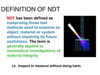

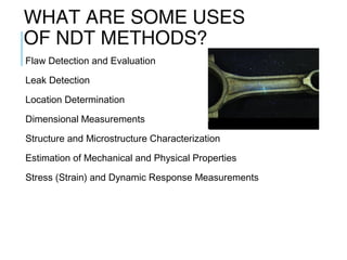
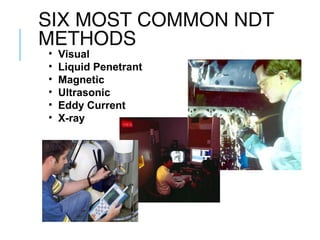
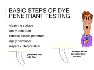
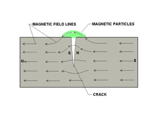
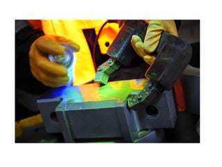
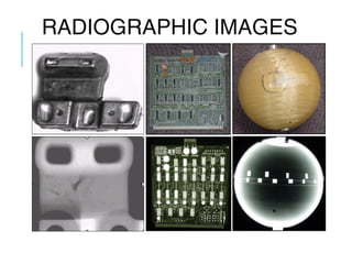
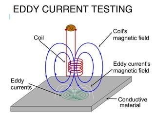
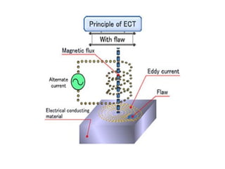
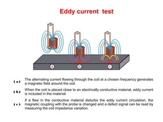
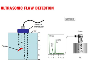
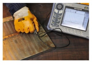
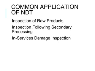


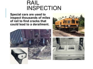


Nondestructive testing (NDT) allows inspection or measurement of materials without causing damage. Common NDT methods include visual testing, liquid penetrant testing, magnetic particle testing, ultrasonic testing, eddy current testing, and radiography. These methods are used to detect inherent, processing, and service defects in raw materials and components, as well as to inspect for in-service damage in applications like aircraft engines, rails, and bridges in order to ensure safety and prevent failures.