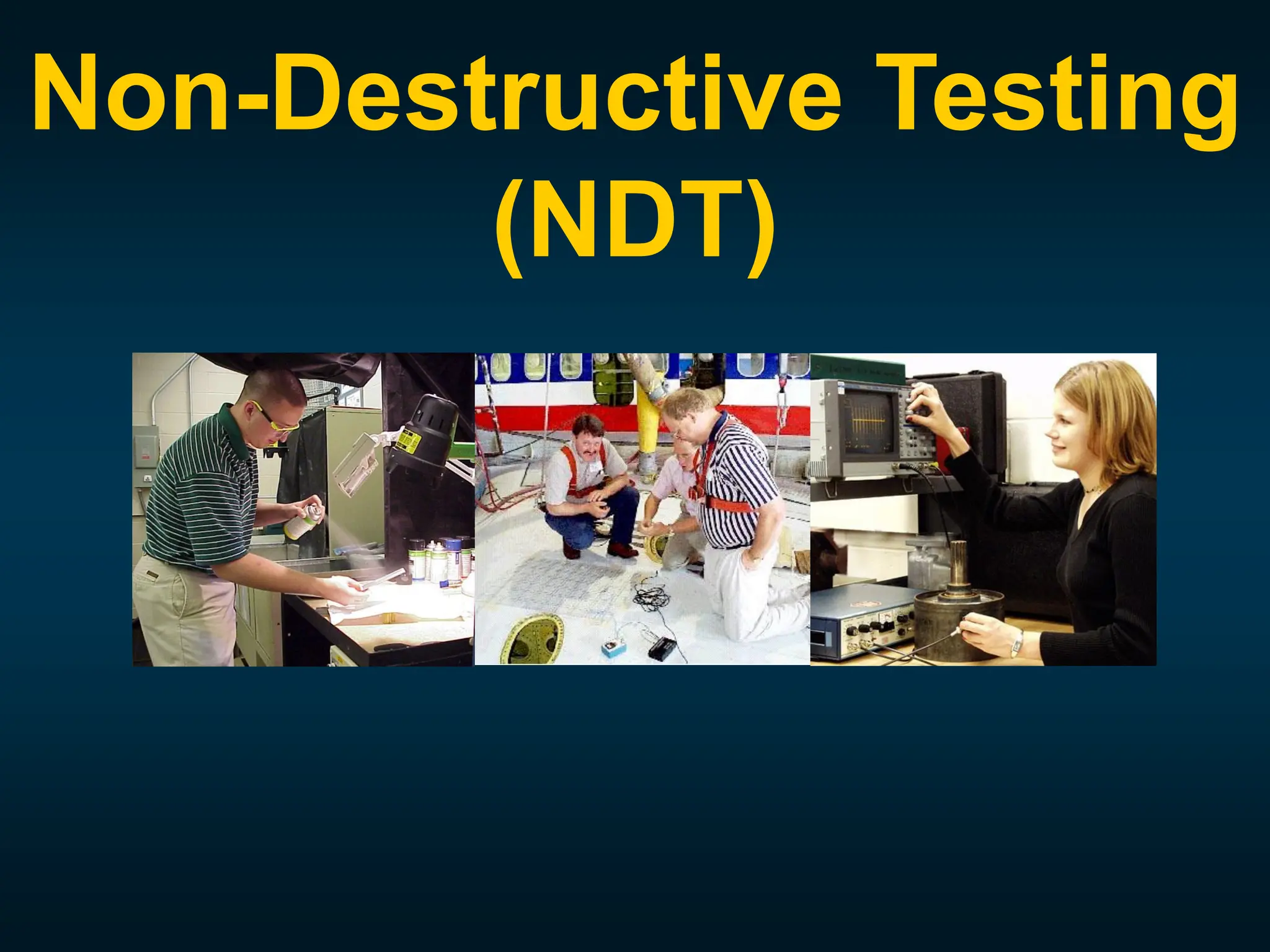
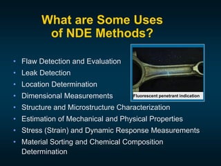
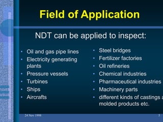
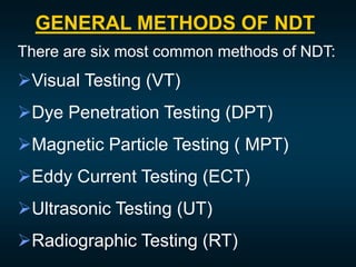
Non-Destructive Testing
(NDT)
24 Nov 1998 2
What is Non-Destructive Testing
(NDT)?
What are Some Uses
of NDE Methods?
• Flaw Detection and Evaluation
• Leak Detection
• Location Determination
• Dimensional Measurements
• Structure and Microstructure Characterization
• Estimation of Mechanical and Physical Properties
• Stress (Strain) and Dynamic Response Measurements
• Material Sorting and Chemical Composition
Determination
Fluorescent penetrant indication
Why Non-Destructive Testing?
• It helps to take a decision about the
serviceability of the machine component.
• It helps to minimize/prevent accident.
• It reduces unscheduled breakdown/shutdown of
the machinery.
• It gives the confidence to the working personnel
of safe working area.
• It reduces wastage of the finished product.
• It improves product quality.
• It minimizes maintenance and production cost.
Field of Application
• Oil and gas pipe lines
• Electricity generating
plants
• Pressure vessels
• Turbines
• Ships
• Aircrafts
24 Nov 1998 5
• Steel bridges
• Fertilizer factories
• Oil refineries
• Chemical industries
• Pharmaceutical industries
• Machinery parts
• different kinds of castings a
molded products etc.
NDT can be applied to inspect:
GENERAL METHODS OF NDT
There are six most common methods of NDT:
Visual Testing (VT)
Dye Penetration Testing (DPT)
Magnetic Particle Testing ( MPT)
Eddy Current Testing (ECT)
Ultrasonic Testing (UT)
Radiographic Testing (RT)
Visual Testing (VT)
- Visual testing is one of the most
common and most powerful means of
non-destructive testing.
- The equipment needed for VT is
simple like a portable light, a mirror, a
hand lens, illuminated magnifier,
borescope etc.
A : Mirror on stem: may be flat for normal view or concave for limited
magnification.
B : Hand magnifying glass (magnification usually 2–3X).
C : Illuminated magnifier.
D : Inspection glass, usually fitted with a scale for measurement.
E : Borescope or intrascope with built-in illumination.
Dye Penetration Testing (DPT)
- This is a method which can be employed for
the detection of open-to-surface
discontinuities in any industrial product which
is made from a non-porous material.
- Defect length of test surface can be accurately
imaged.
- Depth of the defect cannot be determined.
Chemicals Required for DPT
 Dye or Liquid Penetrant.
 Penetrant Cleaner or Remover.
 Developer.
Working Procedure of DPT
 Clean the test surface properly.
 Apply liquid penetrant on the test surface and wait 15-20 min.
 The surface is then dried and a developer is applied to it.
 The penetrant which remains in the discontinuity is absorbed
by the developer to indicate the presence as well as the
location, size and nature of the discontinuity.
Limitation of DPT
 Defects must open to surface.
 Sub-surface and internal defects can’t
detect.
 Very tight and shallow defects difficult
to find.
 Depth of flaw can’t indicate.
Magnetic Particle Testing (MPT)
- Magnetic particle testing successfully detects surface
and near surface defects in ferromagnetic materials
such as steel and iron.
- Magnetic particle inspection is performed by spreading
fine magnetic particles over the surface of a test piece
as it is being magnetized, causing a buildup of particles
at a discontinuity such as a crack, lap, inclusion or
seam.
- These particles have high magnetic permeability, so
they are easily magnetized and attracted to small
magnetic leakage fields caused by discontinuities.
 Magnetic yoke (which the test piece can
magnetize).
 Magnetic particles (dry or wet, fluorescent or
non-fluorescent).
 Black light source (only for fluorescent
particle).
Materials Required for MPT
Testing Procedure of MPT
 Clean the test surface properly.
 Then magnetize the test specimen.
 Apply magnetic particle on the test surface.
 The particles normally only cluster at North and
the South poles of the surface.
 Interpret the accumulation of particles to detect
the nature of defect.
 Demagnetized the test object and finally clean
the test surface.
(a) permanent magnets
(b) Electromagnets
Limitations of MPT
• Only good for ferromagnetic materials
• sub-surface defects will not always be indicated
• relative direction between the magnetic field and the
defect line is important
• objects must be demagnetized before and after the
examination
Examples of visible dry magnetic particle indications
Indication of a crack in a saw blade Indication of cracks in a weldment
Before and after inspection pictures of
Indication of cracks running between
attachment holes in a hinge
Examples of Fluorescent Wet Magnetic
Particle Indications
Magnetic particle wet fluorescent
indication of a cracks in a drive shaft
Magnetic particle wet
fluorescent
indication of a crack
in a bearing
Magnetic particle wet fluorescent indication
of a cracks at a fastener hole
Eddy Current Testing (ECT)
- A circulating electrical current that is
induced in a conductive material by an
alternating magnetic field is called eddy
current.
- This method is applicable to electrically
conductive materials only.
Working Procedure
24 Nov 1998 24
• In order to generate eddy currents for an inspection, a "probe" is used.
• Inside the probe is a length of electrical conductor material which is formed
into a coil
• When alternating current is applied to the conductor, such as copper wire
coil, a primary magnetic field generates in and around the conductor or coil.
• When an electrically conductive material is placed in the coil's dynamic
magnetic field, electromagnetic induction will occur and alternating
currents will be induced in the material.
• This current is in the form of circular loops known as Eddy Currents.
• Eddy currents flowing in the material will generate their own "secondary"
magnetic field which will oppose the coil's "primary" magnetic field.
24 Nov 1998 25
24 Nov 1998 27
•Only conductive materials can be inspected
•Surface must be accessible to the probe
•Skill and training required is more extensive than other
techniques
•Surface finish and and roughness may interfere
•Reference standards needed for setup
•Depth of penetration is limited
•Flaws such as delaminations that lie parallel to the
probe coil winding and probe scan direction are
undetectable
Limitations of ECT
Power Plant Inspection
Probe
Signals produced
by various
amounts of
corrosion
thinning.
Periodically, power plants are
shutdown for inspection.
Inspectors feed eddy current
probes into heat exchanger
tubes to check for corrosion
damage.
Pipe with damage
Wire Rope Inspection
Electromagnetic devices
and visual inspections are
used to find broken wires
and other damage to the
wire rope that is used in
chairlifts, cranes and other
lifting devices.
Storage Tank Inspection
Robotic crawlers
use ultrasound to
inspect the walls of
large above ground
tanks for signs of
thinning due to
corrosion.
Cameras on
long
articulating
arms are used
to inspect
underground
storage tanks
for damage.
Aircraft Inspection
• Nondestructive testing is used
extensively during the
manufacturing of aircraft.
• NDT is also used to find cracks
and corrosion damage during
operation of the aircraft.
• A fatigue crack that started at
the site of a lightning strike is
shown below.
Jet Engine Inspection
• Aircraft engines are overhauled
after being in service for a period
of time.
• They are completely disassembled,
cleaned, inspected and then
reassembled.
• Fluorescent penetrant inspection
is used to check many of the parts
for cracking.
Sioux City, Iowa, July 19, 1989
A defect that went
undetected in an
engine disk was
responsible for
the crash of
United Flight 232.
Crash of United Flight 232
Pressure Vessel Inspection
The failure of a pressure vessel
can result in the rapid release of
a large amount of energy. To
protect against this dangerous
event, the tanks are inspected
using radiography and
ultrasonic testing.
Rail Inspection
Special cars are used to
inspect thousands of miles
of rail to find cracks that
could lead to a derailment.
Bridge Inspection
• The US has 578,000
highway bridges.
• Corrosion, cracking and
other damage can all
affect a bridge’s
performance.
• The collapse of the Silver
Bridge in 1967 resulted in
loss of 47 lives.
• Bridges get a visual
inspection about every 2
years.
• Some bridges are fitted
with acoustic emission
sensors that “listen” for
sounds of cracks growing.
NDT is used to inspect pipelines
to prevent leaks that could
damage the environment. Visual
inspection, radiography and
electromagnetic testing are some
of the NDT methods used.
Remote visual inspection using
a robotic crawler.
Radiography of weld joints.
Magnetic flux leakage inspection.
This device, known as a pig, is
placed in the pipeline and collects
data on the condition of the pipe as it
is pushed along by whatever is being
transported.
Pipeline Inspection
Ultrasonic Testing (UT)
- Ultrasonic testing is a method that uses
ultrasonic sound waves with high
frequencies ranging from 0.1 - 20 MHz,
well above the audible range for hearing
(20Hz - 20 KHz).
- These waves can be directed at
materials to detect flaws, potentially
invisible to the naked eye.
24 Nov 1998 39
24 Nov 1998 40
24 Nov 1998 41
- The process works by utilizing the directional
nature of sound waves, by projecting them at a
material, they'll travel in a straight line through
a material until they encounter a surface with
another medium (such as air) which will then
cause them to reflect back.
- These reflections can be measured and used
to find flaws such as cracks in materials.
24 Nov 1998 43
Radiography Testing (RT)
- Industrial radiography is a test method that uses high energy
radiation to take an extra-ordinary view of objects.
- Radiography is a common medical procedure done to check
bone fractures and body organ condition.
- It is also used in various industrial fields to test materials.
- It has an important purpose in engineering as it is employed to
pin down concealed flaws in materials.
- High energy radiation used for this particular purpose is x-rays
or gamma rays.
- It can penetrate almost anything.
- This method of testing is often applied in inspection of welds,
pressure vessels, pipelines, and high capacity storage vessels.
24 Nov 1998 44
24 Nov 1998 46
Limitation of RT
24 Nov 1998 47
- Access to both sides of the test piece needed.
- Special safety precaution should be followed because
X-ray and gamma ray are very much hazardous.
- Flaws must be oriented parallel to beam for detection.
- Sensitivity decreases with the increases test piece
thickness.

Non-destructive Testing,it's types & process.pdf

  • 1.
  • 2.
    24 Nov 19982 What is Non-Destructive Testing (NDT)?
  • 3.
    What are SomeUses of NDE Methods? • Flaw Detection and Evaluation • Leak Detection • Location Determination • Dimensional Measurements • Structure and Microstructure Characterization • Estimation of Mechanical and Physical Properties • Stress (Strain) and Dynamic Response Measurements • Material Sorting and Chemical Composition Determination Fluorescent penetrant indication
  • 4.
    Why Non-Destructive Testing? •It helps to take a decision about the serviceability of the machine component. • It helps to minimize/prevent accident. • It reduces unscheduled breakdown/shutdown of the machinery. • It gives the confidence to the working personnel of safe working area. • It reduces wastage of the finished product. • It improves product quality. • It minimizes maintenance and production cost.
  • 5.
    Field of Application •Oil and gas pipe lines • Electricity generating plants • Pressure vessels • Turbines • Ships • Aircrafts 24 Nov 1998 5 • Steel bridges • Fertilizer factories • Oil refineries • Chemical industries • Pharmaceutical industries • Machinery parts • different kinds of castings a molded products etc. NDT can be applied to inspect:
  • 6.
    GENERAL METHODS OFNDT There are six most common methods of NDT: Visual Testing (VT) Dye Penetration Testing (DPT) Magnetic Particle Testing ( MPT) Eddy Current Testing (ECT) Ultrasonic Testing (UT) Radiographic Testing (RT)
  • 7.
    Visual Testing (VT) -Visual testing is one of the most common and most powerful means of non-destructive testing. - The equipment needed for VT is simple like a portable light, a mirror, a hand lens, illuminated magnifier, borescope etc.
  • 8.
    A : Mirroron stem: may be flat for normal view or concave for limited magnification. B : Hand magnifying glass (magnification usually 2–3X). C : Illuminated magnifier. D : Inspection glass, usually fitted with a scale for measurement. E : Borescope or intrascope with built-in illumination.
  • 9.
    Dye Penetration Testing(DPT) - This is a method which can be employed for the detection of open-to-surface discontinuities in any industrial product which is made from a non-porous material. - Defect length of test surface can be accurately imaged. - Depth of the defect cannot be determined.
  • 10.
    Chemicals Required forDPT  Dye or Liquid Penetrant.  Penetrant Cleaner or Remover.  Developer.
  • 11.
    Working Procedure ofDPT  Clean the test surface properly.  Apply liquid penetrant on the test surface and wait 15-20 min.  The surface is then dried and a developer is applied to it.  The penetrant which remains in the discontinuity is absorbed by the developer to indicate the presence as well as the location, size and nature of the discontinuity.
  • 13.
    Limitation of DPT Defects must open to surface.  Sub-surface and internal defects can’t detect.  Very tight and shallow defects difficult to find.  Depth of flaw can’t indicate.
  • 14.
    Magnetic Particle Testing(MPT) - Magnetic particle testing successfully detects surface and near surface defects in ferromagnetic materials such as steel and iron. - Magnetic particle inspection is performed by spreading fine magnetic particles over the surface of a test piece as it is being magnetized, causing a buildup of particles at a discontinuity such as a crack, lap, inclusion or seam. - These particles have high magnetic permeability, so they are easily magnetized and attracted to small magnetic leakage fields caused by discontinuities.
  • 17.
     Magnetic yoke(which the test piece can magnetize).  Magnetic particles (dry or wet, fluorescent or non-fluorescent).  Black light source (only for fluorescent particle). Materials Required for MPT
  • 18.
    Testing Procedure ofMPT  Clean the test surface properly.  Then magnetize the test specimen.  Apply magnetic particle on the test surface.  The particles normally only cluster at North and the South poles of the surface.  Interpret the accumulation of particles to detect the nature of defect.  Demagnetized the test object and finally clean the test surface.
  • 19.
  • 20.
    Limitations of MPT •Only good for ferromagnetic materials • sub-surface defects will not always be indicated • relative direction between the magnetic field and the defect line is important • objects must be demagnetized before and after the examination
  • 21.
    Examples of visibledry magnetic particle indications Indication of a crack in a saw blade Indication of cracks in a weldment Before and after inspection pictures of Indication of cracks running between attachment holes in a hinge
  • 22.
    Examples of FluorescentWet Magnetic Particle Indications Magnetic particle wet fluorescent indication of a cracks in a drive shaft Magnetic particle wet fluorescent indication of a crack in a bearing Magnetic particle wet fluorescent indication of a cracks at a fastener hole
  • 23.
    Eddy Current Testing(ECT) - A circulating electrical current that is induced in a conductive material by an alternating magnetic field is called eddy current. - This method is applicable to electrically conductive materials only.
  • 24.
    Working Procedure 24 Nov1998 24 • In order to generate eddy currents for an inspection, a "probe" is used. • Inside the probe is a length of electrical conductor material which is formed into a coil • When alternating current is applied to the conductor, such as copper wire coil, a primary magnetic field generates in and around the conductor or coil. • When an electrically conductive material is placed in the coil's dynamic magnetic field, electromagnetic induction will occur and alternating currents will be induced in the material. • This current is in the form of circular loops known as Eddy Currents. • Eddy currents flowing in the material will generate their own "secondary" magnetic field which will oppose the coil's "primary" magnetic field.
  • 25.
  • 27.
  • 28.
    •Only conductive materialscan be inspected •Surface must be accessible to the probe •Skill and training required is more extensive than other techniques •Surface finish and and roughness may interfere •Reference standards needed for setup •Depth of penetration is limited •Flaws such as delaminations that lie parallel to the probe coil winding and probe scan direction are undetectable Limitations of ECT
  • 29.
    Power Plant Inspection Probe Signalsproduced by various amounts of corrosion thinning. Periodically, power plants are shutdown for inspection. Inspectors feed eddy current probes into heat exchanger tubes to check for corrosion damage. Pipe with damage
  • 30.
    Wire Rope Inspection Electromagneticdevices and visual inspections are used to find broken wires and other damage to the wire rope that is used in chairlifts, cranes and other lifting devices.
  • 31.
    Storage Tank Inspection Roboticcrawlers use ultrasound to inspect the walls of large above ground tanks for signs of thinning due to corrosion. Cameras on long articulating arms are used to inspect underground storage tanks for damage.
  • 32.
    Aircraft Inspection • Nondestructivetesting is used extensively during the manufacturing of aircraft. • NDT is also used to find cracks and corrosion damage during operation of the aircraft. • A fatigue crack that started at the site of a lightning strike is shown below.
  • 33.
    Jet Engine Inspection •Aircraft engines are overhauled after being in service for a period of time. • They are completely disassembled, cleaned, inspected and then reassembled. • Fluorescent penetrant inspection is used to check many of the parts for cracking.
  • 34.
    Sioux City, Iowa,July 19, 1989 A defect that went undetected in an engine disk was responsible for the crash of United Flight 232. Crash of United Flight 232
  • 35.
    Pressure Vessel Inspection Thefailure of a pressure vessel can result in the rapid release of a large amount of energy. To protect against this dangerous event, the tanks are inspected using radiography and ultrasonic testing.
  • 36.
    Rail Inspection Special carsare used to inspect thousands of miles of rail to find cracks that could lead to a derailment.
  • 37.
    Bridge Inspection • TheUS has 578,000 highway bridges. • Corrosion, cracking and other damage can all affect a bridge’s performance. • The collapse of the Silver Bridge in 1967 resulted in loss of 47 lives. • Bridges get a visual inspection about every 2 years. • Some bridges are fitted with acoustic emission sensors that “listen” for sounds of cracks growing.
  • 38.
    NDT is usedto inspect pipelines to prevent leaks that could damage the environment. Visual inspection, radiography and electromagnetic testing are some of the NDT methods used. Remote visual inspection using a robotic crawler. Radiography of weld joints. Magnetic flux leakage inspection. This device, known as a pig, is placed in the pipeline and collects data on the condition of the pipe as it is pushed along by whatever is being transported. Pipeline Inspection
  • 39.
    Ultrasonic Testing (UT) -Ultrasonic testing is a method that uses ultrasonic sound waves with high frequencies ranging from 0.1 - 20 MHz, well above the audible range for hearing (20Hz - 20 KHz). - These waves can be directed at materials to detect flaws, potentially invisible to the naked eye. 24 Nov 1998 39
  • 40.
  • 41.
    24 Nov 199841 - The process works by utilizing the directional nature of sound waves, by projecting them at a material, they'll travel in a straight line through a material until they encounter a surface with another medium (such as air) which will then cause them to reflect back. - These reflections can be measured and used to find flaws such as cracks in materials.
  • 43.
    24 Nov 199843 Radiography Testing (RT) - Industrial radiography is a test method that uses high energy radiation to take an extra-ordinary view of objects. - Radiography is a common medical procedure done to check bone fractures and body organ condition. - It is also used in various industrial fields to test materials. - It has an important purpose in engineering as it is employed to pin down concealed flaws in materials. - High energy radiation used for this particular purpose is x-rays or gamma rays. - It can penetrate almost anything. - This method of testing is often applied in inspection of welds, pressure vessels, pipelines, and high capacity storage vessels.
  • 44.
  • 46.
  • 47.
    Limitation of RT 24Nov 1998 47 - Access to both sides of the test piece needed. - Special safety precaution should be followed because X-ray and gamma ray are very much hazardous. - Flaws must be oriented parallel to beam for detection. - Sensitivity decreases with the increases test piece thickness.