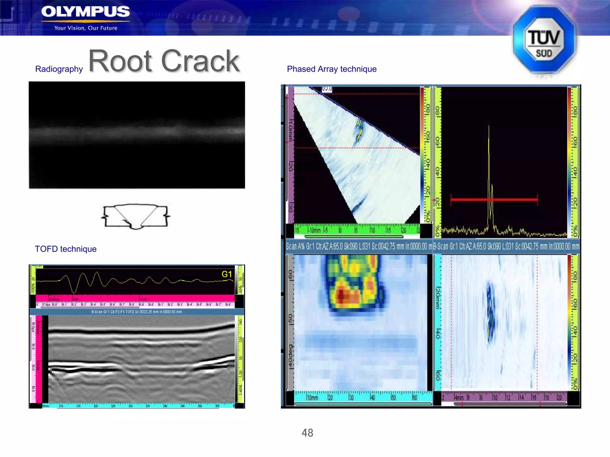
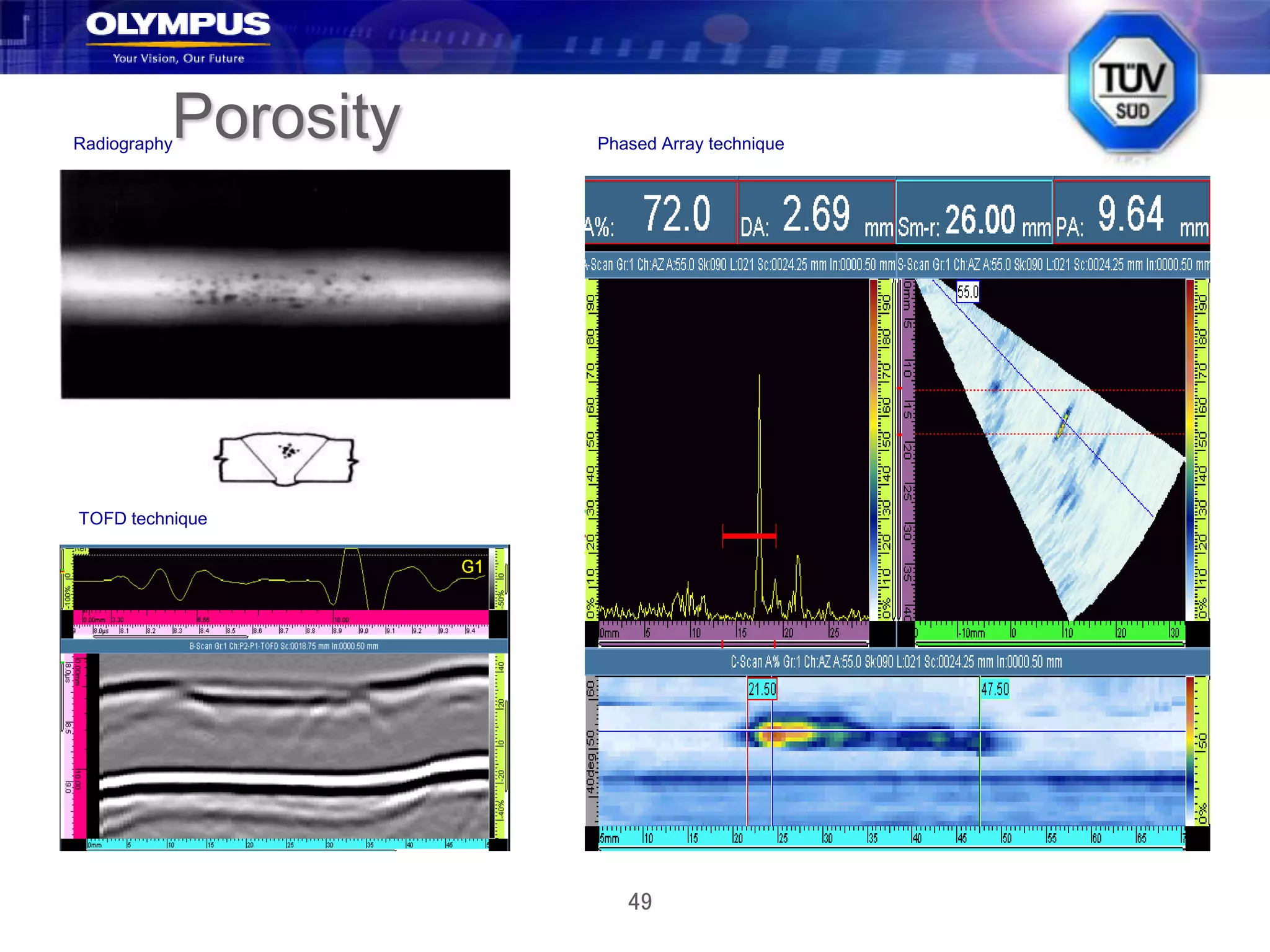
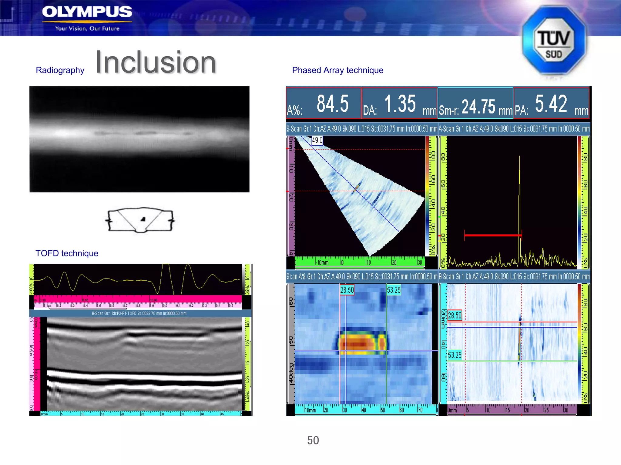
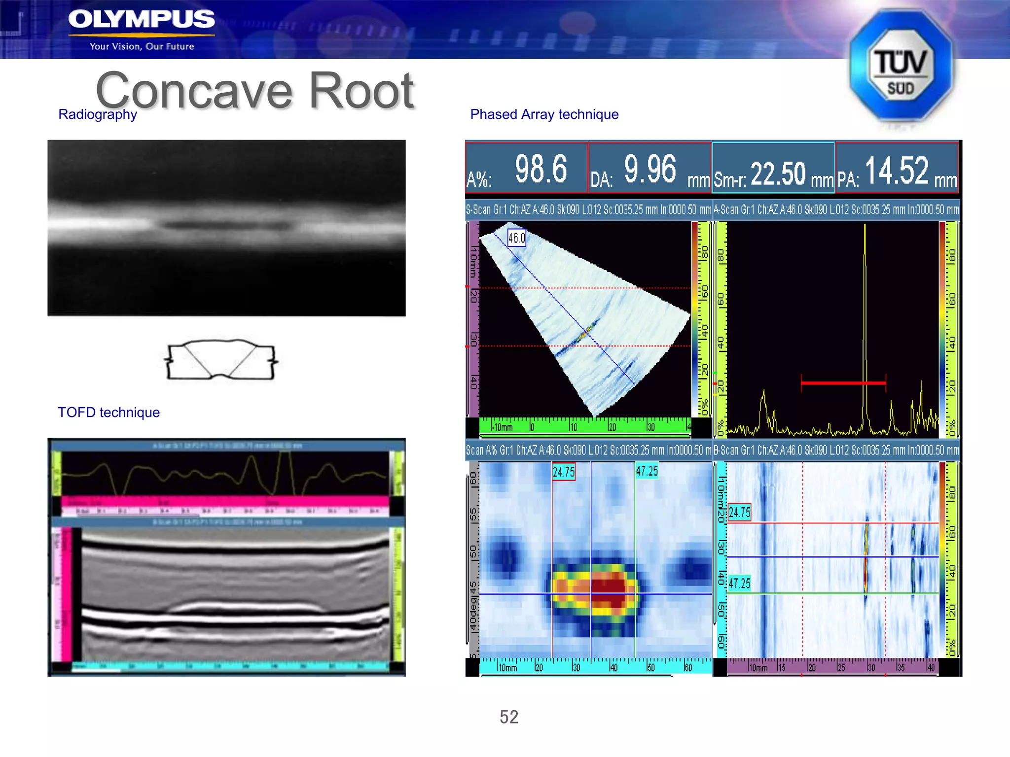
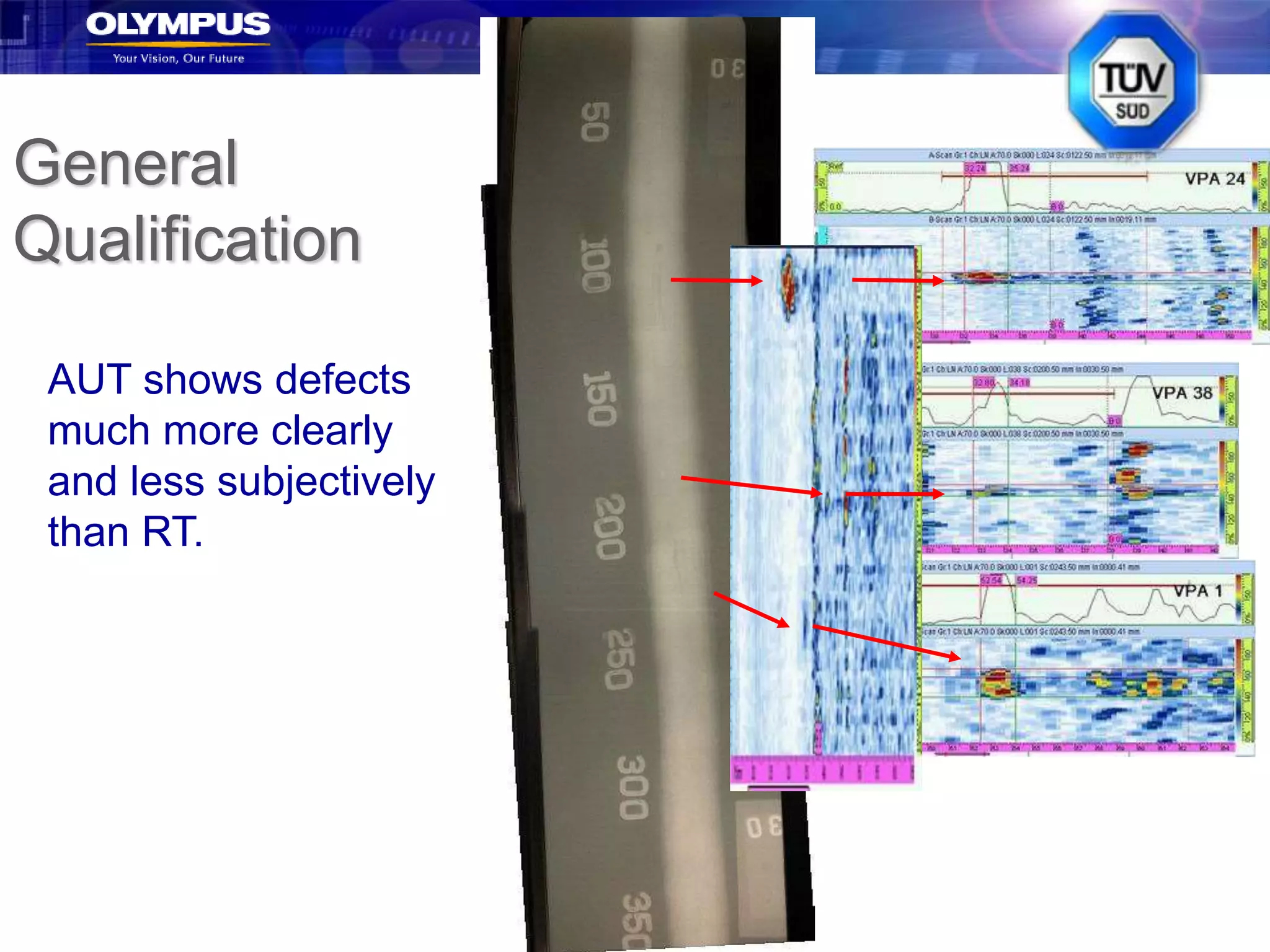
Click to edit Master title style
•Click to edit Master text styles
–Second level
•Third level
–Fourth level
»Fifth level
1
Why AUT??!!!
History and Rationale
2
History
For the last fifty years or more, welds
usually inspected by Radiography
Always based on “workmanship” criteria, not
Fitness-For-Purpose.
(Also called Engineering Critical
Assessment – ECA - or Fracture
Mechanics).
Major problems with radiography:
– Practical
– Technical.
3
Radiography – Practical Problems
Radiation safety
Licensing
Disruption to work area
Chemical wastes
Large volumes of film
Film storage and deterioration
Subjective interpretation
Relatively slow inspection
4
Radiography – Technical Problems
Thinner, stronger vessels under construction
due to:
– Increased resource costs
– Higher strength materials
– Better quality materials
Developments of Fracture Mechanics and
crack growth predictions require defect
depth measurements
=> RT cannot size in vertical plane
=> RT poor at detecting planar defects.
5
Defect Detection by RT
Depends on
defect type
Unfortunately
planar cracks
most difficult
to detect –
and most
critical.
Data from NIL
6
Early Alternative - Manual UT
Manual UT offers:
– Better detection of planar flaws generally
– Better detection of mis-oriented flaws
– No environmental side-effects
– Tailored inspections
BUT, manual UT has major disadvantages
– No permanent record, i.e. not auditable
– Highly subjective, i.e. results can vary
significantly with operator
– Slow
Not a great solution.
7
Comparing MUT vs. RT
Data from NIL
MUT generally better detection, but depends on
threshold level and other factors.
8
AUT (1)
Automated ultrasonics potentially offers
solutions to ECA
Capability of vertical sizing
Better detection of critical planar defects
Inspections tailored to weld profile and
defects
Auditable
Overall, AUT fits in well with ECA concepts,
especially with automated welding.
9
AUT (2)
Generally AUT has better detection than
MUT or RT, especially for cracks
Many trials performed globally (though not
all compare AUT and RT)
Overall results support AUT as better quality
inspections.
10
Sample POD Data (1)
11
Sample POD Data (2)
12
Sample POD Data (3)
Here TOFD
has the best
POD, but
adding TOFD
and PE
Linescanning
would
produce high
POD.
13
POD Results
It must be appreciated that actual POD
results will depend on:
– Techniques used
– Procedures used
– Actual defects in samples
– Component, incl. thickness and material
– Number of data points
– Analysis techniques
– Number of techniques, esp. combinations
Consequently, results do vary, but general
trend is for AUT to be better than RT.
14
AUT vs. RT – Length Measurements
Generally
AUT
better
than RT
or MUT.
15
AUT vs. RT – Depth Sizing
No comparison – RT cannot size. AUT can be
used for ECA.
16
AUT – Sizing Techniques
Left: DDT I round robin sizing using TOFD only.
Right: DDT 1 using all UT techniques.
TOFD and back diffraction offer good sizing.
17
Optimum Solution
Typically, the best solution is to use more
than one technique, especially if
“independent”
Recommend using pulse-echo and TOFD –
essentially independent, and rapid
– PE for detection, with TOFD confirmation;
– TOFD for midwall detection & sizing
– TOFD for sizing with PE confirmation.
Two techniques are complementary.
18
Economics of AUT vs. RT
Until recently, RT cheaper.
Economics swinging towards AUT:
– Higher licensing costs for RT
– Major headaches in shipping and storing
isotopes
– Higher waste disposal, storage etc.
– Cheaper AUT equipment
– More AUT operators available
AUT often cheaper for larger inspection jobs
19
INSPECTION SPEED AND IMPROVED PRODUCTIVITY
 While cost data and productivity are normally proprietary
information, such data that is available shows that much
improved scanning speeds are obtainable. Next Table
compares scan times and productivity from manual UT to
radiography to PA. Not surprisingly, the latest technology
(PA) comes out well in front.
 ASSUMPTIONS:
A. RT: Assume 2 exposures with 50 curie source (which is difficult to
get that highly curie sources all the time)
B. Manual UT: Assume the minimum scanning requirements by
ASME code.
C. Set up time is based on accessibility and test plan.
20
INSPECTION SPEED AND IMPROVED PRODUCTIVITY
Phased Arrays
A quick introduction
22
What are Ultrasonic Phased Arrays
• Ultrasonic Phased arrays use a multiple
element probe whereby the output pulse from
each element is time delayed in such a way so
as produce constructive interference at a
specific angle and a specific depth.
23
Phased Array Probe Configuration
Essentially, a phased-array probe is a long
conventional probe
cut into many small elements, which are
individually excited.
24
Phased Array Probe Configuration
128 elements !
25
How Phased Arrays Work - Beam
Focusing
•large range of
focal depth
(focusing)
• adjustable
each pulse.
26
How Phased Arrays Work - Beam
Steering
• large range of
inspection
angles
(sweeping)
• multiple
modes with a
single probe
(SW, LW)
27
Common Probe Geometries
1D linear array 2D matrix
1D annular array 2D sectorial annular
Linear
Circular
28
Key Concept
Phased arrays do not change the physics
of ultrasound
PA’s are merely a method of generating and
receiving a signal
(and also displaying images)
If you obtain X dB using conventional UT,
you should obtain the same signal amplitude
using PA’s.
29
Phased Array Basics
• For electronic scans, arrays are multiplexed using the same
Focal Law.
• For sectorial scans, the same elements are used, but the
Focal Laws are changed.
• For Dynamic Depth Focusing, the receiver Focal Laws are
only changed in hardware.
30
Electronic Scanning
31
Electronic Scanning
Moves the beam along one axis of
an array without any mechanical
movement.
The movement is performed only
by time multiplexing the active
elements.
32
Electronic Scanning
 Electronic (linear) scanning can easily emulate typical
ASME-type 45 and 60 shear wave inspections, and is
much faster than raster scanning.
 Typical weld inspection requires two or more angles
with implied raster size, step size, etc.
 Need to cover weld, HAZ, any position errors =>
significant amount of scanning
33
Tandem Probes for Vertical Defects
34
Sectorial Scanning Animation
 This illustration shows a turbine blade root being
inspected using S-scans.
35
S-scans - Determining Defect Location
36
Photoelastic Visualization of S-scan
40-70
degree S-
scan on
cal block.
37
But Incident Angles Not Always Optimum!
 Optimum position for array for inspecting upper weld
may not be good for root defects
 Being addressed by ASME codes – need multiple S-
scans.
38
S-scan Imaging Superimposed
S-scan
imaging offers
unique
possibilities for
characterizing
defects and
components.
TOFD – Time-Of-Flight Diffraction
A quick summary
40
Flaw
Diffracted
waves
Diffracted
waves
Incident
wave
Reflected
wave
All directions
Low energy
Independent of
incidence angle
The Diffraction Phenomenon
41
TOFD using Phased Arrays
Transmitter Receiver
Lateral wave
LW
Upper tip Lower tip
Back-wall reflection
BW
42
Diffraction Summary
Incident wave  reflected wave
Incident wave  diffracted waves emitted
by defect boundaries
Cylindrical/spherical waves emitted in all
directions
Amplitude typically 20 to 30 dB below direct
reflection
43
Data Visualization (TOFD)
Lateral
wave
Back wall
A-scan
Indication
44
Typical TOFD Image
Lateral wave
Back-wall echo
45
Advantages of TOFD
 Good midwall defect detection.
 Accurate sizing of defects using the time of
arrivals of diffracted signals.
 Defects mis-oriented defects ,or defects located
away from the weld centreline.
 Very rapid linear scanning (raster scanning not
required)
 Non-amplitude scanning and detection.
 Set-up independent of weld configuration.
46
Limitations of TOFD
 Dead zone at top surface (OD).
 Dead zone at bottom surface (ID).
 Sensitive to very small defects with a
risk of overcalls (add pulse echo).
 Analysis can be difficult.
 Some sizing errors possible from
lateral position of defect.
 Low signal-to-noise ratio.
Sample Comparisons of AUT
and RT
AUT shows better detection than RT
48
Root Crack
TOFD technique
Radiography Phased Array technique
49
Porosity
TOFD technique
Radiography Phased Array technique
50
Inclusion
TOFD technique
Radiography Phased Array technique
51
Lack of Root Fusion
TOFD technique
Radiography Phased Array technique
52
Concave Root
TOFD technique
Radiography Phased Array technique
53
Incomplete Root Penetration
TOFD technique
Radiography
Phased Array technique
54
General
Qualification
AUT shows defects
much more clearly
and less subjectively
than RT.
55
AUT vs. RT – Advantages (1)
Many functional advantages from switching
to AUT
– No radiation
– No licensing
– No chemical wastes
– Less subjective data interpretation
– Minimizes data storage problems
– Minimizes materials handling issues
– Minimizes production disruptions
Benefits depend on application.
56
AUT vs. RT – Advantages (2)
Many technical advantages for AUT,
especially combined Phased Arrays and
TOFD:
– Better detection of planar defects
– Tailored inspections
– Can size in vertical plane for ECA
– Lower reject rates
– Fast and cost effective
– Results auditable
– Well demonstrated for simple welds, e.g. butt
welds.
57
AUT vs. RT – Limitations
All the limitations of ultrasonics apply
New technology – still developing
Shortage of trained AUT operators
Some applications impractical, e.g. nozzles
More work to set up ECA acceptance criteria
Higher initial cost of equipment (but
declining)
Codes, qualifications and training still not
fully developed.
Phased Arrays in Codes
A quick Summary
59
PAUT in Codes
 The dominant code for weld inspection, both
globally and for phased arrays, is ASME,
specifically Section V. ASME has published five
separate Code Cases on phased arrays to cover
both manual and encoded scanning. These Code
Cases specify many of the parameters and
requirements for performing phased array
inspections.
 Other organizations, e.g. the American Petroleum
Institute API, also approve phased arrays, and
follow a similar philosophy.
60
PAUT in Codes
The American Welding Society AWS, also
approve phased arrays.
Many codes allowed using either RT or UT
but the main problem was that there is no
permanent record for UT compared with RT,
So PAUT solved the problem and now you
can use PAUT with a permanent record
which is actually better than RT records.
61
AUT in ASME Codes
 AUT dominated for years by ASME Code Case 2235 (from
Sections I, VIII and XII)
 Now replaced by three Mandatory Appendices (publ. July
2010) in Section V
 No commitment to specific technologies: wide variety of
options - technique, equipment, mechanics, data displays
etc.
62
ASME Mandatory Appendices VI-VIII
 Based on Performance Demonstration (Procedure
Qualification)
 Requires detection of three defects (ID, OD, sub-surface)
 Requires full data collection
 (Modified versions of CC 2235 in API 620 App U, B31.3 CC
181 etc.)
 MUCH easier to read and use than CC 2235
 Written in plain English
 For example, Performance Qualification allows + 25% on
wall thickness and 0.9-1.5 on diameter.
63
Phased Array Codes and Code Cases
 Three AUT Mandatory Appendices (VI-VIII):
a) Workmanship
b) Fracture Mechanics-based
c) Procedure Qualification (Performance Demo)
 Two PA Mandatory Appendices (IV-V):
a) Manual PA (E-scans and S-scans)
b) Encoded linear scanning using linear arrays (E-and S-scans)
64
Phased Array Mand. App. Requirements
 Calibrate all beams (OK for OmniScan)
 Use same Focal Law for cal as for scanning
For encoded scanning:
 Develop Scan Plan to show coverage and
appropriate angles
 Use two (or more) S-scans if required
 Scan parallel to weld with encoder/full data
collection at fixed distance from centerline
65
Phased Array Mand. App. Requirements
 Requires “appropriate angles” for bevel incidence
angles (undefined)
 Usual ‘Essential Variable’ recording requirements
 Requires 50% beam overlap
 Requires <5% data drop-out for encoded scanning
 Extensive reporting requirements.
66
ASME B31.3 Code Case 181 (-2)
 Recently re-written - again
 Currently out for ballot
 Essentially converts CC 181-2 to “workmanship”
 Overall, should be a major step forward for pipes
 In addition, ASME Section V Code Case 2638
allows much greater flexibility in cal blocks.
67
Other Code Activities
API, AWS, ASTM, EN/ISO etc.
68
Code activities - API
 API similar in approach to ASME; two
organizations typically work together
 Approval using PA for API UT 1 and UT 2
procedures with no changes
 Essentially scan known samples using new
technology/techniques
 Phased arrays now widely used for API, e.g. API
RP2X and API 1104.
69
Code activities - AWS
 A “prescriptive” code, different from ASME
 With 2006 version => new technology and
technique approvals are codified
 Working on mandatory Annex for AUT
 AWS D1.1 Ed.2015 Annex Q allows recordable
UT (PAUT) above 6 mm thickness and below that
if qualified by the procedure with engineers
approval.
70
Code activities - ASTM
 ASTM E-2491-06 Recommended Practice for
phased array set-up
 Requires full “angle corrected gain” (ACG) and
“time corrected gain (TCG) over SDH calibration
range
 Limits to angular range based on
recommendations and calibration (Scan Plan).
 Recent E-2700 RP for PA of welds
71
EN/ISO
 Still working on PA code development
 Third version more realistic, but still needs a little
work
 Very bureaucratic organization
 But expect EN/ISO phased array code in a couple
of years.
72
Code activities – ASME summary
 Phased arrays, TOFD and AUT inherently
accepted by ASME (and other codes)
 May need to get techniques and procedures
approved e.g. by Performance Demonstration
approaches
 Complete ASME Phased Array and TOFD (Time-
Of-Flight Diffraction) Codes now available.
73
Code activities – other summary
 ASTM RP for PA set-up published (E-2491)
 ASTM RP for PA of welds published (E- 2700)
 API generally accepts PA
 AWS D1.1 accepts with engineers approval for
procedure.
 Europeans “still behind” on PA and AUT codes.
74
Examples of codes deal with PAUT
 ASME, Section V Article 4.
 ASME Code Cases 2541, 2557, 2558, 2599 and 2600.
 ASME Code Case 2235-11- 2013, “Ultrasonic Examination in Lieu of
Radiography”, ASME Sections I, VIII and XII.
 ASME, Section VIII Div.1 “Using recordable UT in lieu of RT”
 ASME, Section VIII Div.2 “Using recordable UT in lieu of RT”
 ASME B31 Code for pressure piping Code case 181.
 AWS D1.1 Ed.2015.
 API 1104 for pipe lines.
 API 650 “annex U” for above ground tanks inspection.
 API 577 - in-service inspection for piping, pressure vessels and tanks
(Para. 9.9.2.5 & 9.9.2.6).
 ASTM 2491.
 ASTM 2700.
Thank you
Any questions?

371927672-PAUT-and-RT.ppt

  • 1.
    Click to editMaster title style •Click to edit Master text styles –Second level •Third level –Fourth level »Fifth level 1 Why AUT??!!! History and Rationale
  • 2.
    2 History For the lastfifty years or more, welds usually inspected by Radiography Always based on “workmanship” criteria, not Fitness-For-Purpose. (Also called Engineering Critical Assessment – ECA - or Fracture Mechanics). Major problems with radiography: – Practical – Technical.
  • 3.
    3 Radiography – PracticalProblems Radiation safety Licensing Disruption to work area Chemical wastes Large volumes of film Film storage and deterioration Subjective interpretation Relatively slow inspection
  • 4.
    4 Radiography – TechnicalProblems Thinner, stronger vessels under construction due to: – Increased resource costs – Higher strength materials – Better quality materials Developments of Fracture Mechanics and crack growth predictions require defect depth measurements => RT cannot size in vertical plane => RT poor at detecting planar defects.
  • 5.
    5 Defect Detection byRT Depends on defect type Unfortunately planar cracks most difficult to detect – and most critical. Data from NIL
  • 6.
    6 Early Alternative -Manual UT Manual UT offers: – Better detection of planar flaws generally – Better detection of mis-oriented flaws – No environmental side-effects – Tailored inspections BUT, manual UT has major disadvantages – No permanent record, i.e. not auditable – Highly subjective, i.e. results can vary significantly with operator – Slow Not a great solution.
  • 7.
    7 Comparing MUT vs.RT Data from NIL MUT generally better detection, but depends on threshold level and other factors.
  • 8.
    8 AUT (1) Automated ultrasonicspotentially offers solutions to ECA Capability of vertical sizing Better detection of critical planar defects Inspections tailored to weld profile and defects Auditable Overall, AUT fits in well with ECA concepts, especially with automated welding.
  • 9.
    9 AUT (2) Generally AUThas better detection than MUT or RT, especially for cracks Many trials performed globally (though not all compare AUT and RT) Overall results support AUT as better quality inspections.
  • 10.
  • 11.
  • 12.
    12 Sample POD Data(3) Here TOFD has the best POD, but adding TOFD and PE Linescanning would produce high POD.
  • 13.
    13 POD Results It mustbe appreciated that actual POD results will depend on: – Techniques used – Procedures used – Actual defects in samples – Component, incl. thickness and material – Number of data points – Analysis techniques – Number of techniques, esp. combinations Consequently, results do vary, but general trend is for AUT to be better than RT.
  • 14.
    14 AUT vs. RT– Length Measurements Generally AUT better than RT or MUT.
  • 15.
    15 AUT vs. RT– Depth Sizing No comparison – RT cannot size. AUT can be used for ECA.
  • 16.
    16 AUT – SizingTechniques Left: DDT I round robin sizing using TOFD only. Right: DDT 1 using all UT techniques. TOFD and back diffraction offer good sizing.
  • 17.
    17 Optimum Solution Typically, thebest solution is to use more than one technique, especially if “independent” Recommend using pulse-echo and TOFD – essentially independent, and rapid – PE for detection, with TOFD confirmation; – TOFD for midwall detection & sizing – TOFD for sizing with PE confirmation. Two techniques are complementary.
  • 18.
    18 Economics of AUTvs. RT Until recently, RT cheaper. Economics swinging towards AUT: – Higher licensing costs for RT – Major headaches in shipping and storing isotopes – Higher waste disposal, storage etc. – Cheaper AUT equipment – More AUT operators available AUT often cheaper for larger inspection jobs
  • 19.
    19 INSPECTION SPEED ANDIMPROVED PRODUCTIVITY  While cost data and productivity are normally proprietary information, such data that is available shows that much improved scanning speeds are obtainable. Next Table compares scan times and productivity from manual UT to radiography to PA. Not surprisingly, the latest technology (PA) comes out well in front.  ASSUMPTIONS: A. RT: Assume 2 exposures with 50 curie source (which is difficult to get that highly curie sources all the time) B. Manual UT: Assume the minimum scanning requirements by ASME code. C. Set up time is based on accessibility and test plan.
  • 20.
    20 INSPECTION SPEED ANDIMPROVED PRODUCTIVITY
  • 21.
  • 22.
    22 What are UltrasonicPhased Arrays • Ultrasonic Phased arrays use a multiple element probe whereby the output pulse from each element is time delayed in such a way so as produce constructive interference at a specific angle and a specific depth.
  • 23.
    23 Phased Array ProbeConfiguration Essentially, a phased-array probe is a long conventional probe cut into many small elements, which are individually excited.
  • 24.
    24 Phased Array ProbeConfiguration 128 elements !
  • 25.
    25 How Phased ArraysWork - Beam Focusing •large range of focal depth (focusing) • adjustable each pulse.
  • 26.
    26 How Phased ArraysWork - Beam Steering • large range of inspection angles (sweeping) • multiple modes with a single probe (SW, LW)
  • 27.
    27 Common Probe Geometries 1Dlinear array 2D matrix 1D annular array 2D sectorial annular Linear Circular
  • 28.
    28 Key Concept Phased arraysdo not change the physics of ultrasound PA’s are merely a method of generating and receiving a signal (and also displaying images) If you obtain X dB using conventional UT, you should obtain the same signal amplitude using PA’s.
  • 29.
    29 Phased Array Basics •For electronic scans, arrays are multiplexed using the same Focal Law. • For sectorial scans, the same elements are used, but the Focal Laws are changed. • For Dynamic Depth Focusing, the receiver Focal Laws are only changed in hardware.
  • 30.
  • 31.
    31 Electronic Scanning Moves thebeam along one axis of an array without any mechanical movement. The movement is performed only by time multiplexing the active elements.
  • 32.
    32 Electronic Scanning  Electronic(linear) scanning can easily emulate typical ASME-type 45 and 60 shear wave inspections, and is much faster than raster scanning.  Typical weld inspection requires two or more angles with implied raster size, step size, etc.  Need to cover weld, HAZ, any position errors => significant amount of scanning
  • 33.
    33 Tandem Probes forVertical Defects
  • 34.
    34 Sectorial Scanning Animation This illustration shows a turbine blade root being inspected using S-scans.
  • 35.
    35 S-scans - DeterminingDefect Location
  • 36.
    36 Photoelastic Visualization ofS-scan 40-70 degree S- scan on cal block.
  • 37.
    37 But Incident AnglesNot Always Optimum!  Optimum position for array for inspecting upper weld may not be good for root defects  Being addressed by ASME codes – need multiple S- scans.
  • 38.
    38 S-scan Imaging Superimposed S-scan imagingoffers unique possibilities for characterizing defects and components.
  • 39.
    TOFD – Time-Of-FlightDiffraction A quick summary
  • 40.
  • 41.
    41 TOFD using PhasedArrays Transmitter Receiver Lateral wave LW Upper tip Lower tip Back-wall reflection BW
  • 42.
    42 Diffraction Summary Incident wave reflected wave Incident wave  diffracted waves emitted by defect boundaries Cylindrical/spherical waves emitted in all directions Amplitude typically 20 to 30 dB below direct reflection
  • 43.
  • 44.
    44 Typical TOFD Image Lateralwave Back-wall echo
  • 45.
    45 Advantages of TOFD Good midwall defect detection.  Accurate sizing of defects using the time of arrivals of diffracted signals.  Defects mis-oriented defects ,or defects located away from the weld centreline.  Very rapid linear scanning (raster scanning not required)  Non-amplitude scanning and detection.  Set-up independent of weld configuration.
  • 46.
    46 Limitations of TOFD Dead zone at top surface (OD).  Dead zone at bottom surface (ID).  Sensitive to very small defects with a risk of overcalls (add pulse echo).  Analysis can be difficult.  Some sizing errors possible from lateral position of defect.  Low signal-to-noise ratio.
  • 47.
    Sample Comparisons ofAUT and RT AUT shows better detection than RT
  • 48.
  • 49.
  • 50.
  • 51.
    51 Lack of RootFusion TOFD technique Radiography Phased Array technique
  • 52.
  • 53.
    53 Incomplete Root Penetration TOFDtechnique Radiography Phased Array technique
  • 54.
    54 General Qualification AUT shows defects muchmore clearly and less subjectively than RT.
  • 55.
    55 AUT vs. RT– Advantages (1) Many functional advantages from switching to AUT – No radiation – No licensing – No chemical wastes – Less subjective data interpretation – Minimizes data storage problems – Minimizes materials handling issues – Minimizes production disruptions Benefits depend on application.
  • 56.
    56 AUT vs. RT– Advantages (2) Many technical advantages for AUT, especially combined Phased Arrays and TOFD: – Better detection of planar defects – Tailored inspections – Can size in vertical plane for ECA – Lower reject rates – Fast and cost effective – Results auditable – Well demonstrated for simple welds, e.g. butt welds.
  • 57.
    57 AUT vs. RT– Limitations All the limitations of ultrasonics apply New technology – still developing Shortage of trained AUT operators Some applications impractical, e.g. nozzles More work to set up ECA acceptance criteria Higher initial cost of equipment (but declining) Codes, qualifications and training still not fully developed.
  • 58.
    Phased Arrays inCodes A quick Summary
  • 59.
    59 PAUT in Codes The dominant code for weld inspection, both globally and for phased arrays, is ASME, specifically Section V. ASME has published five separate Code Cases on phased arrays to cover both manual and encoded scanning. These Code Cases specify many of the parameters and requirements for performing phased array inspections.  Other organizations, e.g. the American Petroleum Institute API, also approve phased arrays, and follow a similar philosophy.
  • 60.
    60 PAUT in Codes TheAmerican Welding Society AWS, also approve phased arrays. Many codes allowed using either RT or UT but the main problem was that there is no permanent record for UT compared with RT, So PAUT solved the problem and now you can use PAUT with a permanent record which is actually better than RT records.
  • 61.
    61 AUT in ASMECodes  AUT dominated for years by ASME Code Case 2235 (from Sections I, VIII and XII)  Now replaced by three Mandatory Appendices (publ. July 2010) in Section V  No commitment to specific technologies: wide variety of options - technique, equipment, mechanics, data displays etc.
  • 62.
    62 ASME Mandatory AppendicesVI-VIII  Based on Performance Demonstration (Procedure Qualification)  Requires detection of three defects (ID, OD, sub-surface)  Requires full data collection  (Modified versions of CC 2235 in API 620 App U, B31.3 CC 181 etc.)  MUCH easier to read and use than CC 2235  Written in plain English  For example, Performance Qualification allows + 25% on wall thickness and 0.9-1.5 on diameter.
  • 63.
    63 Phased Array Codesand Code Cases  Three AUT Mandatory Appendices (VI-VIII): a) Workmanship b) Fracture Mechanics-based c) Procedure Qualification (Performance Demo)  Two PA Mandatory Appendices (IV-V): a) Manual PA (E-scans and S-scans) b) Encoded linear scanning using linear arrays (E-and S-scans)
  • 64.
    64 Phased Array Mand.App. Requirements  Calibrate all beams (OK for OmniScan)  Use same Focal Law for cal as for scanning For encoded scanning:  Develop Scan Plan to show coverage and appropriate angles  Use two (or more) S-scans if required  Scan parallel to weld with encoder/full data collection at fixed distance from centerline
  • 65.
    65 Phased Array Mand.App. Requirements  Requires “appropriate angles” for bevel incidence angles (undefined)  Usual ‘Essential Variable’ recording requirements  Requires 50% beam overlap  Requires <5% data drop-out for encoded scanning  Extensive reporting requirements.
  • 66.
    66 ASME B31.3 CodeCase 181 (-2)  Recently re-written - again  Currently out for ballot  Essentially converts CC 181-2 to “workmanship”  Overall, should be a major step forward for pipes  In addition, ASME Section V Code Case 2638 allows much greater flexibility in cal blocks.
  • 67.
    67 Other Code Activities API,AWS, ASTM, EN/ISO etc.
  • 68.
    68 Code activities -API  API similar in approach to ASME; two organizations typically work together  Approval using PA for API UT 1 and UT 2 procedures with no changes  Essentially scan known samples using new technology/techniques  Phased arrays now widely used for API, e.g. API RP2X and API 1104.
  • 69.
    69 Code activities -AWS  A “prescriptive” code, different from ASME  With 2006 version => new technology and technique approvals are codified  Working on mandatory Annex for AUT  AWS D1.1 Ed.2015 Annex Q allows recordable UT (PAUT) above 6 mm thickness and below that if qualified by the procedure with engineers approval.
  • 70.
    70 Code activities -ASTM  ASTM E-2491-06 Recommended Practice for phased array set-up  Requires full “angle corrected gain” (ACG) and “time corrected gain (TCG) over SDH calibration range  Limits to angular range based on recommendations and calibration (Scan Plan).  Recent E-2700 RP for PA of welds
  • 71.
    71 EN/ISO  Still workingon PA code development  Third version more realistic, but still needs a little work  Very bureaucratic organization  But expect EN/ISO phased array code in a couple of years.
  • 72.
    72 Code activities –ASME summary  Phased arrays, TOFD and AUT inherently accepted by ASME (and other codes)  May need to get techniques and procedures approved e.g. by Performance Demonstration approaches  Complete ASME Phased Array and TOFD (Time- Of-Flight Diffraction) Codes now available.
  • 73.
    73 Code activities –other summary  ASTM RP for PA set-up published (E-2491)  ASTM RP for PA of welds published (E- 2700)  API generally accepts PA  AWS D1.1 accepts with engineers approval for procedure.  Europeans “still behind” on PA and AUT codes.
  • 74.
    74 Examples of codesdeal with PAUT  ASME, Section V Article 4.  ASME Code Cases 2541, 2557, 2558, 2599 and 2600.  ASME Code Case 2235-11- 2013, “Ultrasonic Examination in Lieu of Radiography”, ASME Sections I, VIII and XII.  ASME, Section VIII Div.1 “Using recordable UT in lieu of RT”  ASME, Section VIII Div.2 “Using recordable UT in lieu of RT”  ASME B31 Code for pressure piping Code case 181.  AWS D1.1 Ed.2015.  API 1104 for pipe lines.  API 650 “annex U” for above ground tanks inspection.  API 577 - in-service inspection for piping, pressure vessels and tanks (Para. 9.9.2.5 & 9.9.2.6).  ASTM 2491.  ASTM 2700.
  • 75.