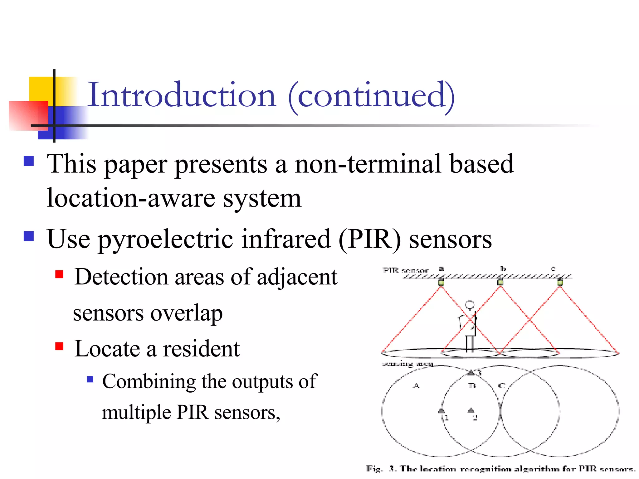
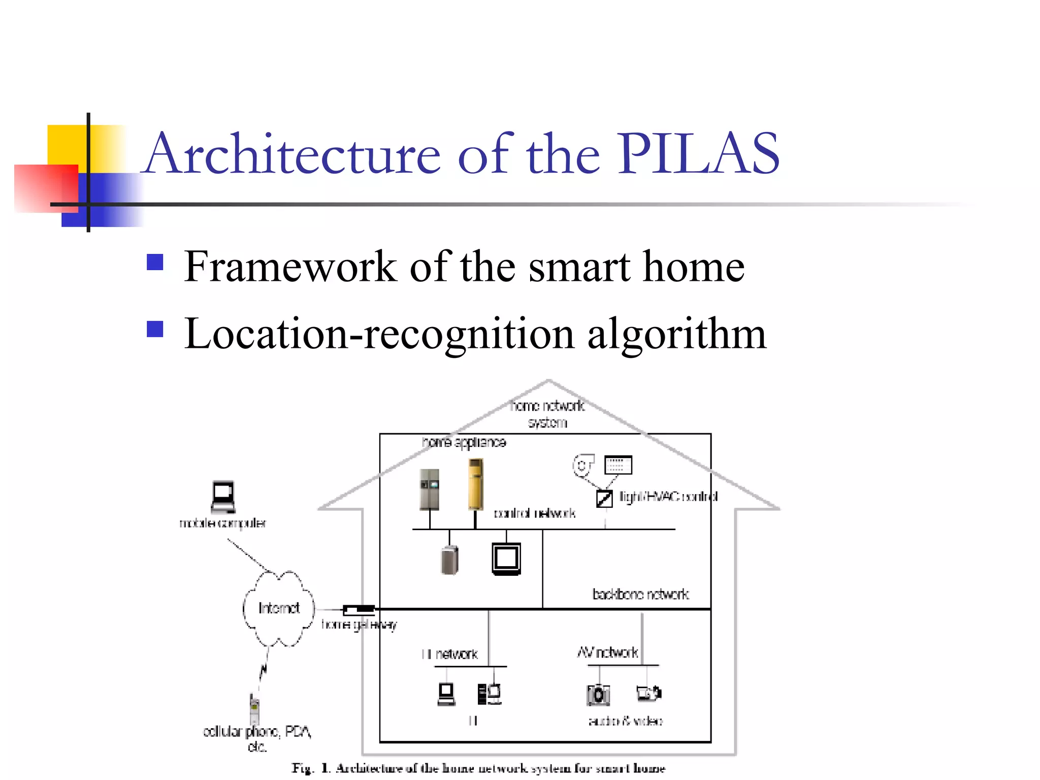
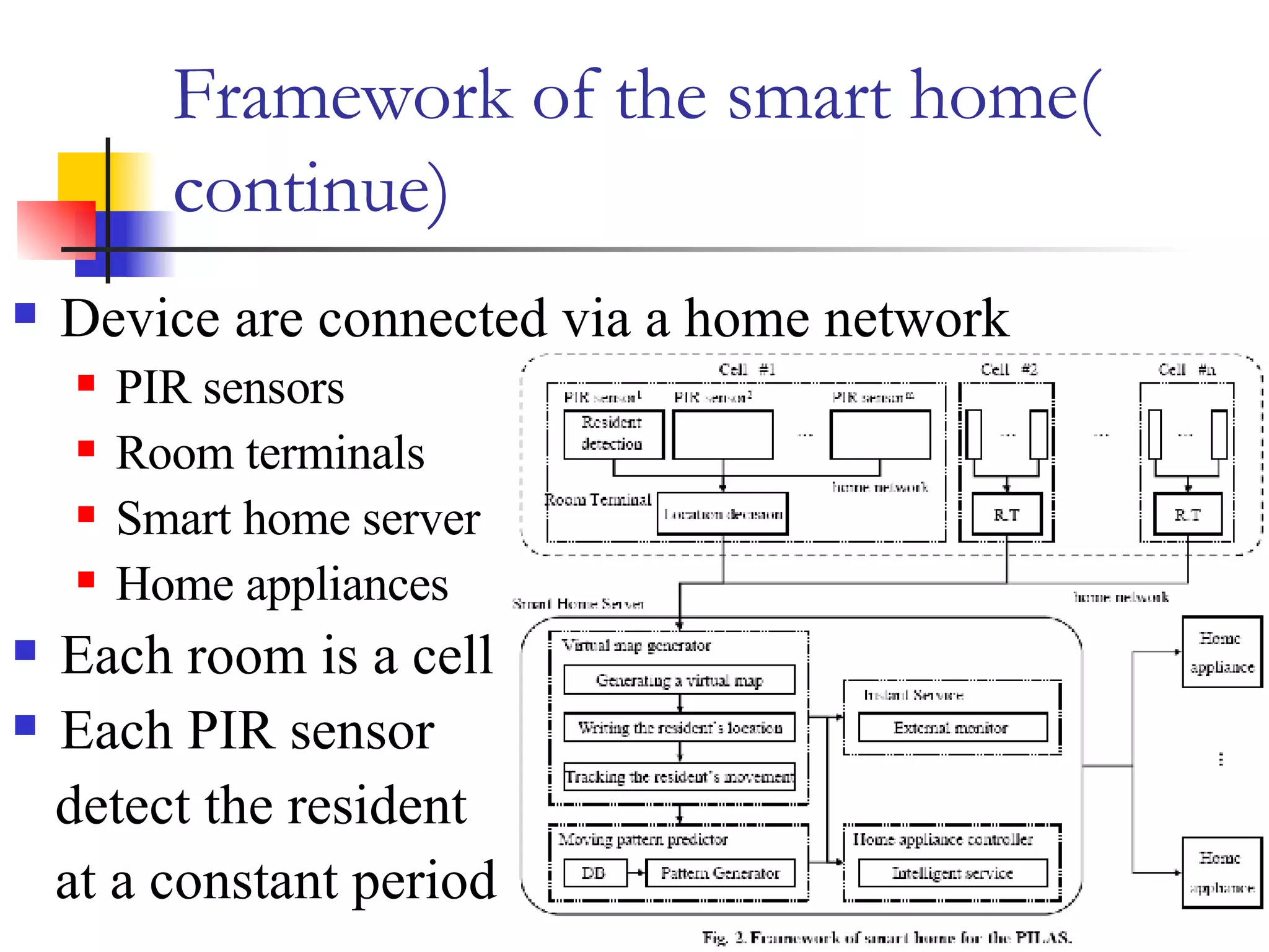
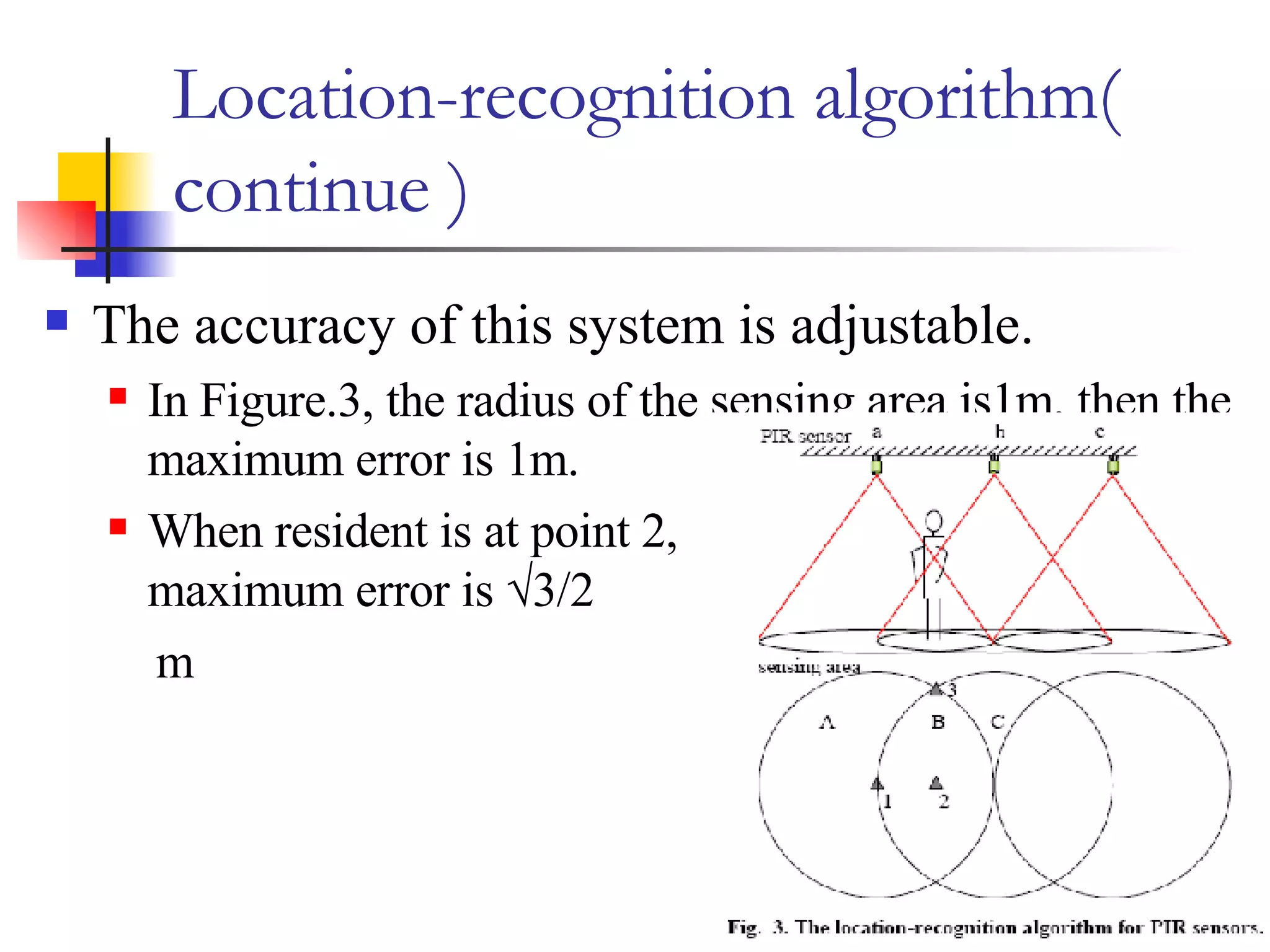
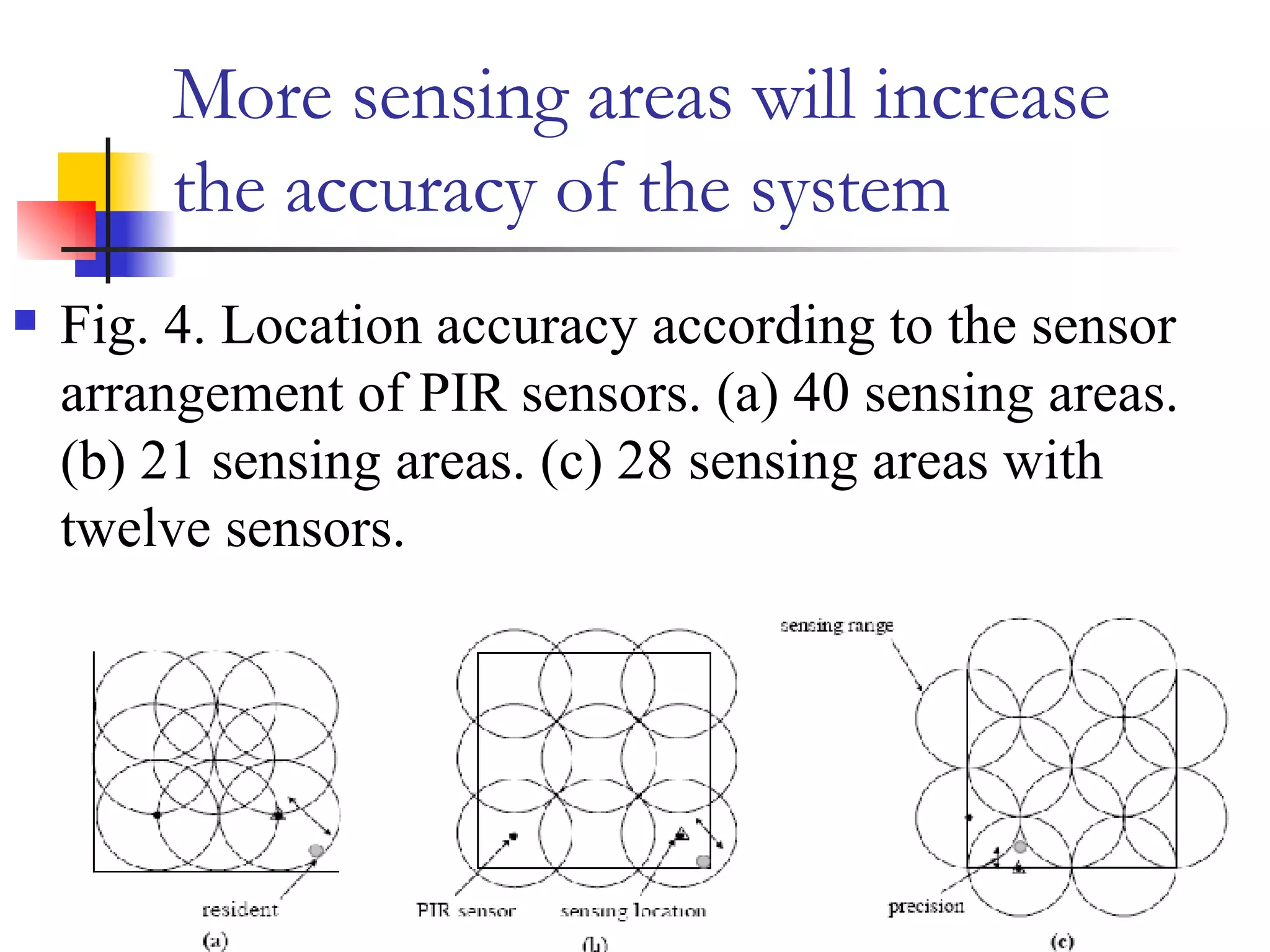
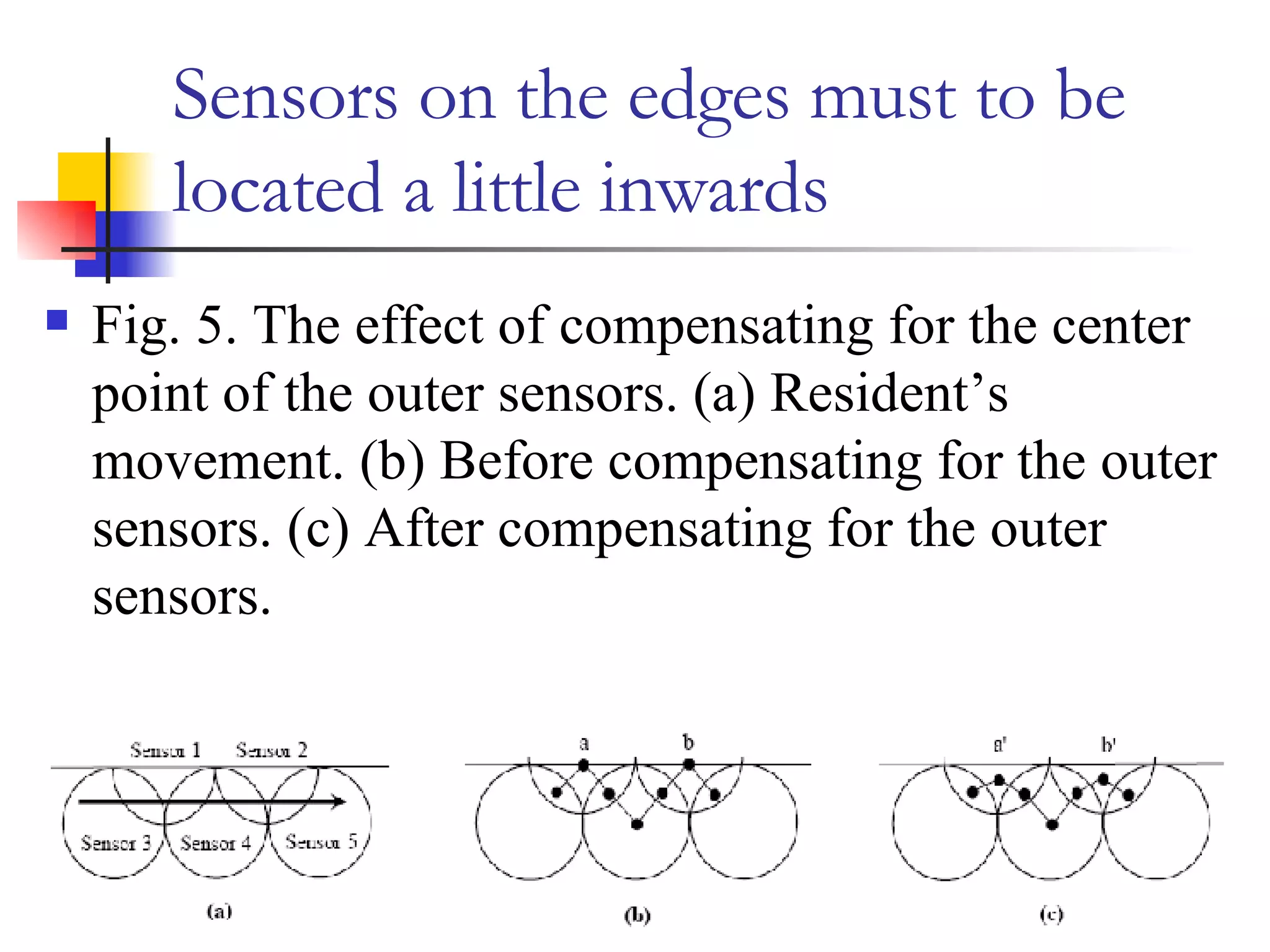
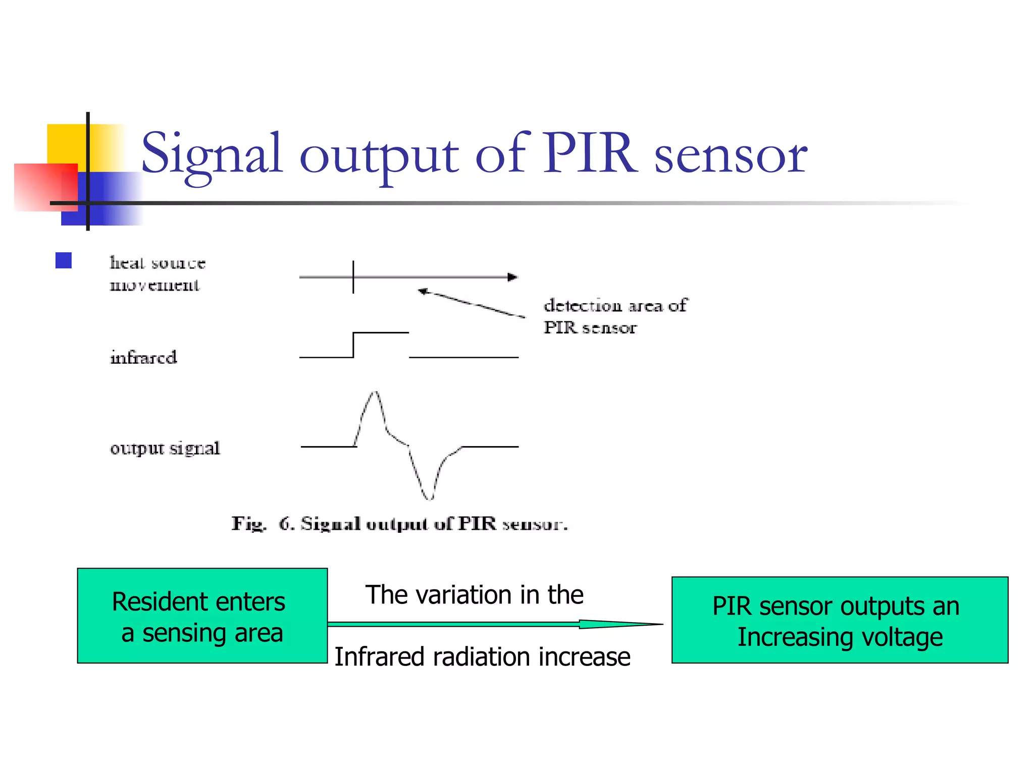
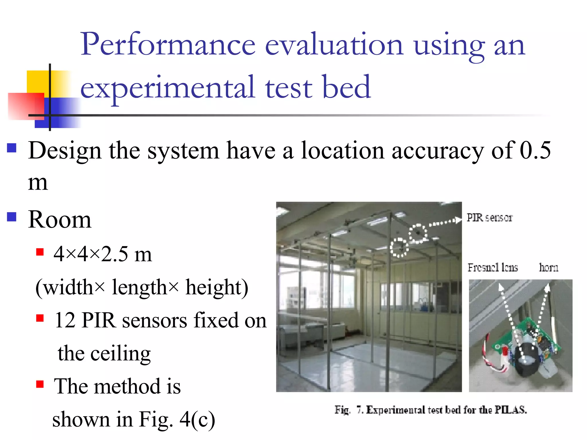
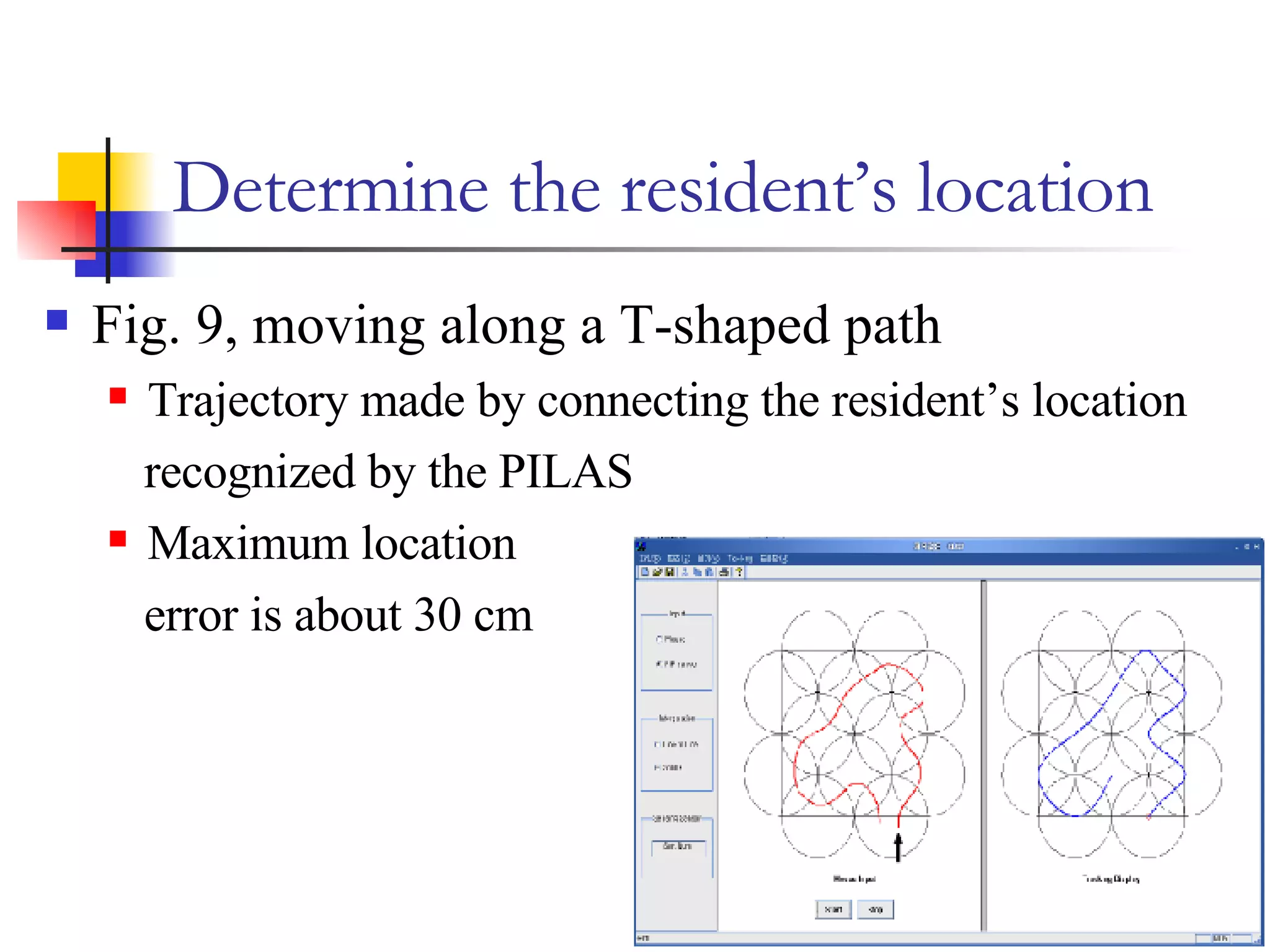
A Pyroelectric Infrared Sensor-based Indoor Location-Aware System for the Smart Home 指導老師 : 張耀仁 學生 : 莊育嘉
Reference   S Lee, KN Ha, KC Lee - Consumer Electronics, IEEE Transactions on, 2006 - ieeexplore.ieee.org
Outline   Abstract  Introduction  Architecture of the PILAS ( PIR Sensor-Based Indoor Location-Aware System) Performance evaluation of the PILAS Summary and conclusions
Abstract Key issue of smart home how to detect the locations of resident Two approaches of research effort Terminal-based Resident must carry a type of device  Non-terminal-based Resident don’t carry such device This paper use non-terminal-based approach Pyroelectric infrared sensors( PIR sensors)
Introduction How to enhance a resident’s convenience and safety multimedia appliance Internet appliances were connected via a home network system Controlled or monitored remotely using a TV or PDA Location-based service Can anticipate the resident Offer appropriate intelligent service
Introduction (continued) According to the measurement technology, indoor location-aware system have been classified into three types Triangulation Scene analysis Proximity methods
Triangulation   This method uses multiple distances from multiple known points.  Example Active Badges Use infrared sensors Active Bats Use ultrasonic sensors Easy Living Use vision sensors
Scene analysis The Scene analysis method examines a view from a particular vantage point. Examples  MotionStar Use a DC magnetic tracker RADAR Use IEEE 802.11 local area network (LAN)
Proximity methods The proximity methods measures nearness to a known set of points. Example  Smart Floor Uses pressure sensors
Introduction (continued) According to the need for terminal should be carried by the resident, indoor location-aware system have been classified into two types. Terminal-based method Non-terminal method
Terminal-based methods Active Bats Use RFID tag Use infrared transceiver It is impossible to recognize the resident’s location when user didn’t carry such devices.
Non-terminal methods This method can find resident’s location without such devices Easy Living Be regarded to invade the resident’s privacy  Smart Floor This method has difficulty with extendibility and maintenance
Introduction (continued) This paper presents a non-terminal based location-aware system Use pyroelectric infrared (PIR) sensors  Detection areas of adjacent  sensors overlap  Locate a resident Combining the outputs of  multiple PIR sensors,
Architecture of the PILAS Framework of the smart home Location-recognition algorithm
Framework of the smart home An indoor location-aware system must satisfy the following requirements Location-aware system should be implemented relatively low cost Sensor installation must be flexible Sensors have to be robust to noise Sensors should not be affected by their surroundings It is desirable that the system’s accuracy is adjustable according to room types
Advantage of PIR sensors Have been used to turn on a light when it detects human movements Less expensive Robust to surroundings Infrared detect wavelength between 9.4~10.4μm In terms of temperature, humidity, electromagnetic noise Possible to control the accuracy  Easily installed on the ceiling
Framework of the smart home( continue) Device are connected via a home network PIR sensors Room terminals Smart home server Home appliances Each room is a cell Each PIR sensor detect the resident at a constant period
Functions in smart home server Generating a virtual map Writing the resident’s movement Provide intelligence services Via the home network  Save the current information  Movement trajectory of the resident  Current action of home appliance Current home environment May offer human-oriented intelligent services
Location-recognition algorithm In Fig. 3, Resident in 1 a output ‘ON’, b and c outputs ‘OFF’ In Fig. 3, Resident in 2 a and b output ‘ON’, c outputs ‘OFF’ If three or more sensors signal ‘ON’, the resident is located at the centroid of the centers
Location-recognition algorithm( continue ) The accuracy of this system is adjustable. In Figure.3, the radius of the sensing area is1m, then the maximum error is 1m. When resident is at point 2,  the maximum error is √3/2 m
More sensing areas will increase  the accuracy of the system Fig. 4. Location accuracy according to the sensor arrangement of PIR sensors. (a) 40 sensing areas. (b) 21 sensing areas. (c) 28 sensing areas with twelve sensors.
Sensors on the edges must to be located a little inwards   Fig. 5. The effect of compensating for the center point of the outer sensors. (a) Resident’s movement. (b) Before compensating for the outer sensors. (c) After compensating for the outer sensors.
Performance evaluation of the PILAS Resident-detection method using PIR sensors The requirements of resident-detection method Implementation method for the resident-detection method for PIR sensors  Performance evaluation using an experimental test bed
Resident-detection method using PIR sensors Recognize the resident’s location by combining outputs from all the sensors belonging to one cell Every sensor’s state will influence location accuracy the ‘ON’/’OF’ values can be determined by comparing a predefined threshold and the digitized sensor output acquired by sampling the analog signal from a PIR sensor It’s important to find appropriate threshold
Signal output of PIR sensor Resident enters  a sensing area The variation in the Infrared radiation increase PIR sensor outputs an  Increasing voltage
The requirements of resident-detection method PIR sensors must not malfunction by other disturbance It should be possible to precisely determine the point in time, include resident’s speed and height. It is necessary to know if a resident stays within the sensing area
The resident -detection method for PIR sensors (continue) Use Fresnel lens Allows human waveforms to pass through it while reject other waveforms To eliminate malfunctioning due to pets or temperature changes  Resident  has entered a sensing area  Output of a PIR sensor exceeds the positive threshold voltage  This state maintained for several intervals
The resident -detection method for PIR sensors (continue) Threshold must be sufficient for the method The method can distinguish variation between the resident’s infrared and other’s infrared The resident has left Sensor’s output falls below a negative threshold voltage The status maintained for several sampling intervals A resident stays within the sensing area Output voltage remains between two threshold voltage
Performance evaluation using an experimental test bed Design the system have a location accuracy of 0.5 m  Room 4×4×2.5 m  (width× length× height) 12 PIR sensors fixed on the ceiling The method is  shown in Fig. 4(c)
Performance evaluation using an experimental test bed (continue) Signal processing and judging ‘ON/OFF’ Atmel AT89C51CC001 microcontroller A Nippon Ceramic RE431B PIR sensor NL-11 Fresnel lens  A horn was installed on each PIR sensor to limit the sensing area to the circle with 2 m diameter
Performance evaluation using an experimental test bed (continue) Fig. 8 shows the experimental results with the horn In a, walk straight  line In b, moves within  the circle In c, moves outside  the circle
Choose threshold  To judge the signal is ’ON’ or ‘OFF’ When the threshold of the RE431B was ‘  ‘ This  value based on the the respect to the internal temperature change  External environmental temperature change didn’t affect its performance at detecting the resident Pets didn’t affect the performance
Determine the resident’s location PC-based location recognition algorithm Collected data every 10msec Use an NI 6025E data acquisition (DAQ) board In Fig. 9 It was drawn using a mouse in left window On the right is the estimated movement trajectory of resident
Determine the resident’s location Fig. 9, moving along a T-shaped path Trajectory made by connecting the resident’s location  recognized by the PILAS Maximum location  error is about 30 cm
Summary and conclusions The location accuracy in this paper is lower than 0.5 m It is possible to enhance the location accuracy of the system This system should be extended to deal with a room occupied by more than one resident

A Pyroelectric Infrared Sensor

  • 1.
    A Pyroelectric InfraredSensor-based Indoor Location-Aware System for the Smart Home 指導老師 : 張耀仁 學生 : 莊育嘉
  • 2.
    Reference S Lee, KN Ha, KC Lee - Consumer Electronics, IEEE Transactions on, 2006 - ieeexplore.ieee.org
  • 3.
    Outline Abstract Introduction Architecture of the PILAS ( PIR Sensor-Based Indoor Location-Aware System) Performance evaluation of the PILAS Summary and conclusions
  • 4.
    Abstract Key issueof smart home how to detect the locations of resident Two approaches of research effort Terminal-based Resident must carry a type of device Non-terminal-based Resident don’t carry such device This paper use non-terminal-based approach Pyroelectric infrared sensors( PIR sensors)
  • 5.
    Introduction How toenhance a resident’s convenience and safety multimedia appliance Internet appliances were connected via a home network system Controlled or monitored remotely using a TV or PDA Location-based service Can anticipate the resident Offer appropriate intelligent service
  • 6.
    Introduction (continued) Accordingto the measurement technology, indoor location-aware system have been classified into three types Triangulation Scene analysis Proximity methods
  • 7.
    Triangulation This method uses multiple distances from multiple known points. Example Active Badges Use infrared sensors Active Bats Use ultrasonic sensors Easy Living Use vision sensors
  • 8.
    Scene analysis TheScene analysis method examines a view from a particular vantage point. Examples MotionStar Use a DC magnetic tracker RADAR Use IEEE 802.11 local area network (LAN)
  • 9.
    Proximity methods Theproximity methods measures nearness to a known set of points. Example Smart Floor Uses pressure sensors
  • 10.
    Introduction (continued) Accordingto the need for terminal should be carried by the resident, indoor location-aware system have been classified into two types. Terminal-based method Non-terminal method
  • 11.
    Terminal-based methods ActiveBats Use RFID tag Use infrared transceiver It is impossible to recognize the resident’s location when user didn’t carry such devices.
  • 12.
    Non-terminal methods Thismethod can find resident’s location without such devices Easy Living Be regarded to invade the resident’s privacy Smart Floor This method has difficulty with extendibility and maintenance
  • 13.
    Introduction (continued) Thispaper presents a non-terminal based location-aware system Use pyroelectric infrared (PIR) sensors Detection areas of adjacent sensors overlap Locate a resident Combining the outputs of multiple PIR sensors,
  • 14.
    Architecture of thePILAS Framework of the smart home Location-recognition algorithm
  • 15.
    Framework of thesmart home An indoor location-aware system must satisfy the following requirements Location-aware system should be implemented relatively low cost Sensor installation must be flexible Sensors have to be robust to noise Sensors should not be affected by their surroundings It is desirable that the system’s accuracy is adjustable according to room types
  • 16.
    Advantage of PIRsensors Have been used to turn on a light when it detects human movements Less expensive Robust to surroundings Infrared detect wavelength between 9.4~10.4μm In terms of temperature, humidity, electromagnetic noise Possible to control the accuracy Easily installed on the ceiling
  • 17.
    Framework of thesmart home( continue) Device are connected via a home network PIR sensors Room terminals Smart home server Home appliances Each room is a cell Each PIR sensor detect the resident at a constant period
  • 18.
    Functions in smarthome server Generating a virtual map Writing the resident’s movement Provide intelligence services Via the home network Save the current information Movement trajectory of the resident Current action of home appliance Current home environment May offer human-oriented intelligent services
  • 19.
    Location-recognition algorithm InFig. 3, Resident in 1 a output ‘ON’, b and c outputs ‘OFF’ In Fig. 3, Resident in 2 a and b output ‘ON’, c outputs ‘OFF’ If three or more sensors signal ‘ON’, the resident is located at the centroid of the centers
  • 20.
    Location-recognition algorithm( continue) The accuracy of this system is adjustable. In Figure.3, the radius of the sensing area is1m, then the maximum error is 1m. When resident is at point 2, the maximum error is √3/2 m
  • 21.
    More sensing areaswill increase the accuracy of the system Fig. 4. Location accuracy according to the sensor arrangement of PIR sensors. (a) 40 sensing areas. (b) 21 sensing areas. (c) 28 sensing areas with twelve sensors.
  • 22.
    Sensors on theedges must to be located a little inwards Fig. 5. The effect of compensating for the center point of the outer sensors. (a) Resident’s movement. (b) Before compensating for the outer sensors. (c) After compensating for the outer sensors.
  • 23.
    Performance evaluation ofthe PILAS Resident-detection method using PIR sensors The requirements of resident-detection method Implementation method for the resident-detection method for PIR sensors Performance evaluation using an experimental test bed
  • 24.
    Resident-detection method usingPIR sensors Recognize the resident’s location by combining outputs from all the sensors belonging to one cell Every sensor’s state will influence location accuracy the ‘ON’/’OF’ values can be determined by comparing a predefined threshold and the digitized sensor output acquired by sampling the analog signal from a PIR sensor It’s important to find appropriate threshold
  • 25.
    Signal output ofPIR sensor Resident enters a sensing area The variation in the Infrared radiation increase PIR sensor outputs an Increasing voltage
  • 26.
    The requirements ofresident-detection method PIR sensors must not malfunction by other disturbance It should be possible to precisely determine the point in time, include resident’s speed and height. It is necessary to know if a resident stays within the sensing area
  • 27.
    The resident -detectionmethod for PIR sensors (continue) Use Fresnel lens Allows human waveforms to pass through it while reject other waveforms To eliminate malfunctioning due to pets or temperature changes Resident has entered a sensing area Output of a PIR sensor exceeds the positive threshold voltage This state maintained for several intervals
  • 28.
    The resident -detectionmethod for PIR sensors (continue) Threshold must be sufficient for the method The method can distinguish variation between the resident’s infrared and other’s infrared The resident has left Sensor’s output falls below a negative threshold voltage The status maintained for several sampling intervals A resident stays within the sensing area Output voltage remains between two threshold voltage
  • 29.
    Performance evaluation usingan experimental test bed Design the system have a location accuracy of 0.5 m Room 4×4×2.5 m (width× length× height) 12 PIR sensors fixed on the ceiling The method is shown in Fig. 4(c)
  • 30.
    Performance evaluation usingan experimental test bed (continue) Signal processing and judging ‘ON/OFF’ Atmel AT89C51CC001 microcontroller A Nippon Ceramic RE431B PIR sensor NL-11 Fresnel lens A horn was installed on each PIR sensor to limit the sensing area to the circle with 2 m diameter
  • 31.
    Performance evaluation usingan experimental test bed (continue) Fig. 8 shows the experimental results with the horn In a, walk straight line In b, moves within the circle In c, moves outside the circle
  • 32.
    Choose threshold To judge the signal is ’ON’ or ‘OFF’ When the threshold of the RE431B was ‘ ‘ This value based on the the respect to the internal temperature change External environmental temperature change didn’t affect its performance at detecting the resident Pets didn’t affect the performance
  • 33.
    Determine the resident’slocation PC-based location recognition algorithm Collected data every 10msec Use an NI 6025E data acquisition (DAQ) board In Fig. 9 It was drawn using a mouse in left window On the right is the estimated movement trajectory of resident
  • 34.
    Determine the resident’slocation Fig. 9, moving along a T-shaped path Trajectory made by connecting the resident’s location recognized by the PILAS Maximum location error is about 30 cm
  • 35.
    Summary and conclusionsThe location accuracy in this paper is lower than 0.5 m It is possible to enhance the location accuracy of the system This system should be extended to deal with a room occupied by more than one resident