Download as PDF, PPTX
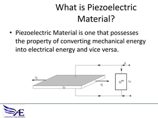
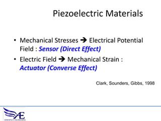
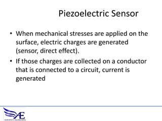
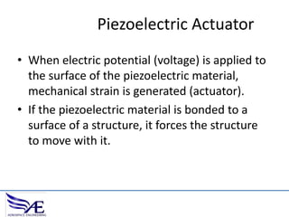

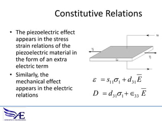
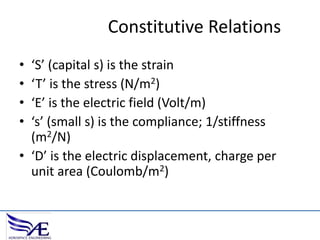
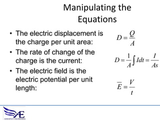
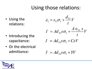
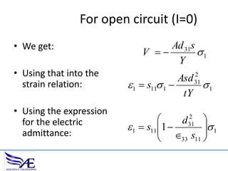
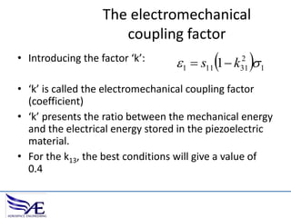
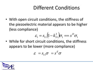
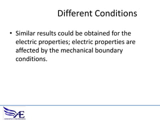
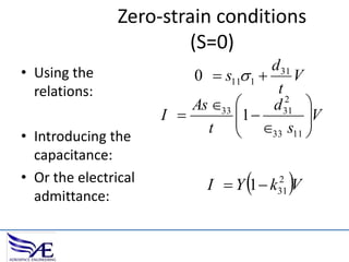
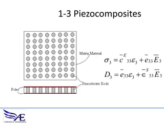
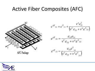
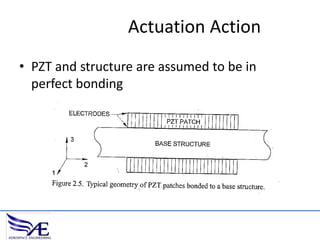
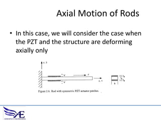
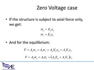
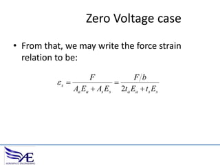
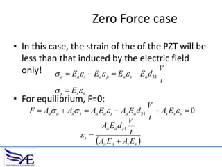

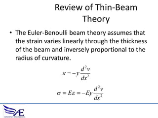
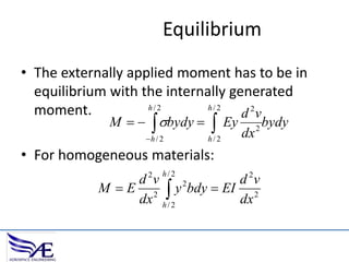
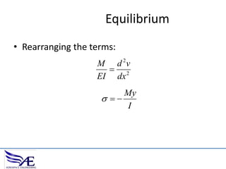
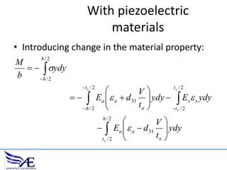
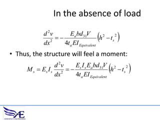
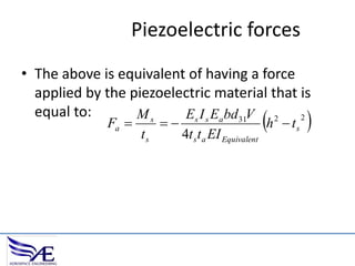


The document discusses piezoelectric materials, which convert mechanical energy to electrical energy and vice versa, detailing their functioning as sensors and actuators. It also covers equations related to the electromechanical coupling and different conditions affecting piezoelectric properties, alongside applications like vibration control and hybrid control systems. Additionally, it provides insights into homework assignments involving piezoelectric beams and the review of thin-beam theory.