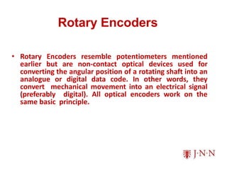
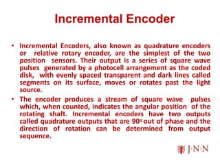
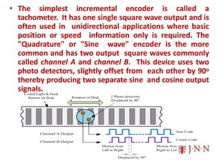
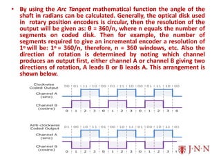
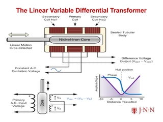
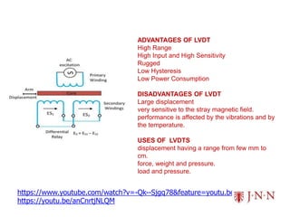
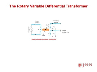
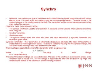
JNN INSTITUTE OF
ENGINEERING
MT8591– SENSORS AND INSTRUMENTATION
MALATHY N, ASSISTANT PROFESSOR
Department of ROBOTICS & AUTOMATION
 Motion Sensors – Potentiometers, Resolver, Encoders –
Optical, Magnetic, Inductive, Capacitive, LVDT – RVDT –
Synchro – Microsyn, Accelerometer – GPS, Bluetooth,
Range Sensors – RF beacons, Ultrasonic Ranging,
Reflective beacons, Laser Range Sensor (LIDAR)
UNIT II MOTION, PROXIMITY AND RANGING
SENSORS
MOTION SENSOR
The main objective of this unit is to study the specific measuring devices with
motion and dimensional measurements, because they are based on two
fundamental quantities length and time. Generally many physical quantities
such as force, pressure, temperature, etc. are often measured by transducing
them to motion and then measuring the resulting motion.
The sense of concern is on motion which is change in displacement. Motion
detection is the process of determining a change in the position of an object
respective to its surroundings or a change in the surroundings relative to an
object. Detection of Motion can be achieved by either mechanical or electronic
methods. Motion controllers are used as game controllers in video game
consoles.
MOTION SENSOR
A motion sensor are often referred as motion detector. Motion sensor is an
electronic device that detect and measure movement of objects or human
being. It performs a task automatically and alerts the human of a motion in an
area.
Motion sensors are typically embedded systems with three major components:
(i) a sensor unit,
(ii) an embedded computer, and
(iii)hardware (or the mechanical component).
These three parts vary in size and configuration, as motion sensors can be
customized to perform highly specific functions.
They are widely used in security systems, automated home control, activating
automatic door openers in public buildings, etc. motion sensors can be used to
activate floodlights, trigger audible alarms, activate switches, and even alert the
police.
TYPES OF MOTION SENSORS
1. Passive infrared sensor (PIR)
2. Ultrasonic sensor
3. Microwave/ RADAR type sensor
PASSIVE INFRARED SENSOR (PIR)
• Passive infrared sensor (PIR sensor) is an electronic sensor that has the
ability to detect and measures infrared (IR) light radiating from objects in
its field of view. PIR is designed to detect the infrared radiation emitted
naturally from the human body is shown in the Fig. 1.
• The term “passive” indicates that the sensor does not actively take part in the
process, which means, it does not emit the referred IR signals itself, rather
passively detects the infrared radiations coming from the human body in the
surrounding area.
• PRINCIPLE OF OPERATION
• Generation of output signal
• PIRs have a pyro electric sensor that detects levels of infrared radiation –
everything emits some low-level radiation, but a human body emits a good
amount of heat. The PIR has two slots made of a special material that is
sensitive to infrared. When the sensor senses a differential change
between the two slots, this causes a pulse, which is what it detects as
“movement”. The filter is present in the receiver allows infrared to pass
through it. When a person walks into the PIR sensor’s field of detection, the
difference in radiation creates a positive charge within the receiver; this
detected change causes the sensing unit to send electrical data to the
embedded computer and hardware component.
• The detected radiations are converted into an electrical charge, which is
proportional to the detected level of the radiation is shown in the Fig.2. Then
this charge is further improved by a built in FET and fed to the output pin of
the device which becomes applicable to an external circuit for further
triggering and amplification of the alarm stages. The PIR sensor range is up
to 10 meters at an angle of +150 or -150.
• The below Fig .3 shows a typical pin configuration of the PIR sensor, which
is quite simple to understand the pinouts; and, one may easily arrange
them into a working circuit with the help of the following points:
• The Passive infrared sensors consist of three pins as indicated in the
diagram shown in Fig. 3. Pin 1 corresponds to the drain terminal of the
device, which should be connected to the positive supply 5V DC.Pin 2
corresponds to the source terminal of the device, which should be
connected to the ground terminal via a 100K or 47K resistor. The Pin2 is the
output pin of the sensor, and the detected IR signal is carried forward to an
amplifier from the pin 2 of the sensor.Pin3 of the sensor is connected to the
ground.
• Figure 4. PIR Sensor
Working Principle
• The PIR sensors are more complicated than the other sensors as they
consists of two slots. These slots are made of a special material which is
sensitive to IR. The Fresnel len into the PIR sensor circuit is shown in Fig. 4
used to see that the two slots of the PIR can see out past some distance.
When the sensor is inactive, then the two slots sense the same amount of
IR. The ambient amount radiates from the outdoors, walls or room, etc.
• When a human body or any animal passes by, then it intercepts the first slot
of the PIR sensor. This causes a positive differential change between the
two bisects. When a human body leaves the sensing area, the sensor
generates a negative differential change between the two bisects. The
infrared sensor itself is housed in a hermetically sealed metal to improve
humidity/temperature/noise/immunity. There is a window which is made of
typically coated silicon material to protect the sensing element.
• Video Link:
https://www.youtube.com/watch?v=JIk2LCgtF20&feature=youtu.be
The PIR sensor is internally split into two
halves as shown in the Fig 5, one is
positive and the other is considered as
negative. Thus, one half generates one
signal by detecting the motion of a hot
body and other half generates another
signal. The difference between these two
signals is generated as output signal.
Primarily, this sensor consists of Fresnel
lens which are bifurcated to detect the
infrared radiation produced by the motion
of hot body over a wide range or specific
area.
Applications
• Intruder alarms
• Automatic ticket gates
• Entryway lighting
• Security lighting
• Hand dryers
• Automatic doors
• Ultrasonic sensors are used for triggering the security camera at home and
for wildlife photography.
• Active infrared sensors used To indicate the presence of products on
conveyor belts
ULTRASONIC SENSOR
• An ultrasonic sensor is an electronic device which measures the distance of a
target object by emitting ultrasonic sound waves, and converts the reflected
sound into an electrical signal.
• Ultrasonic waves travel faster than the speed of audible sound (i.e. the sound
that humans can hear). Ultrasonic sensors have two main components: the
transmitter (which emits the sound using piezoelectric crystals) and the receiver
(which encounters the sound after it has travelled to and from the target).
• It sends an ultrasonic pulse out at 40kHz which travels through the air and if
there is an obstacle or object, it will bounce back to the sensor. By calculating
the travel time and the speed of sound, the distance can be calculated.
• In order to calculate the distance between the sensor and the object, the sensor
measures the time it takes between the emission of the sound by the transmitter
to its contact with the receiver. The formula for this calculation is
• D = ½ T x C
• Where,
• D is the distance
• T is the time
• C is the speed of sound ~ 343 meters/second.
• The value is multiplied by 1/2 because T is the time for go-and-return distance
ULTRASONIC SENSOR - OPERATION
• When an electrical pulse of high voltage is applied to the ultrasonic
transducer it vibrates across a specific spectrum of frequencies and
generates a burst of sound waves. Whenever any obstacle comes ahead of
the ultrasonic sensor the sound waves will reflect back in the form of echo
and generates an electric pulse as shown in Fig. 7. It calculates the time
taken between sending sound waves and receiving the echo. The echo
patterns will be compared with the patterns of sound waves to determine
the detected signal’s condition.
ULTRASONIC SENSOR
• Ultrasonic sensors are used primarily as proximity sensors. They can be
found in automobile self-parking technology and anti-collision safety
systems. Ultrasonic sensors are also used in robotic obstacle detection
systems, as well as manufacturing technology. In comparison to infrared
(IR) sensors in proximity sensing applications, ultrasonic sensors are not as
susceptible to interference of smoke, gas, and other airborne particles
(though the physical components are still affected by variables such as
heat).
APPLICATIONS
• Ultrasonic sensors are also used as
• Level sensors to detect, monitor, and regulate liquid levels in closed
containers (such as vats in chemical factories).
• Factory automation
• Water-level sensing
• Aquatic application
• Can even measure fluid flow rates.
MICROWAVE/ RADAR TYPE SENSOR
• Microwave motion sensor systems send out microwaves that bounce off an
object and back to the sensor
• The sensor then reads the frequency of the returning waves.
• If an object is moving, the sensor receives different microwaves than the
ones it sent out, signifying movement and setting off the alarm
• These types of motion sensor systems cover a larger area than infrared
sensors, they are capable of penetrating walls.
• They are more reliable over longer distances.
• Their radiation is unhealthy for living organisms.
• Despite this, they are the least popular motion sensor system on the
market because of their cost.
• Video Link:
https://www.youtube.com/watch?v=JNQAH3VMFTU&feature=youtu.be
POTENTIOMETERS
• Potentiometer sensor measures the distance or displacement of an object in
a linear or rotary motion and converts it into an electrical signal.
Potentiometer is one of the common sensors for position measurements. A
resistance potentiometer or a pot consists of resistive element provided with
a sliding contact. The sliding contact is called a wiper. The motion of the
sliding contact may be translator or rotational. Some pot uses the
combination of two motions i.e. translational as well as rotational.
• The potentiometer is also called as pots and it one of the most commonly
used devise for measuring the displacement of the body. The potentiometer
is the electrical type of transducer or sensor and it is of resistive type
because it works on the principle of change of resistance of the wire with its
length. The resistance of the wire is directly proportional to the length of the
wire, thus as the length of the wire changes the resistance of the wire also
changes.
• R = ρⅬ /A
• Where, ρ – Resistivity, L – Length, A – Area.
Types of Potentiometer
• Linear or Translational Potentiometer
• Rotary Potentiometer
• Helipot
Construction of Potentiometer
• The potentiometer has three terminals, the two terminals are attached to the
resistor, and the wiper is attached to the third terminal, which is movable
with the wire. Because of this moving wire, the variable potential is tapped
off. The third terminal is used for controlling the variable resistor. The
potential of the third terminal is controlled by changing the applying potential
at the end of the resistor. The body of the potentiometer is made up of
resistive material, and the wire is wound on it.
Linear or Translational Potentiometer (to
measure the linear displacement)
Rotary Potentiometer (to measure the angular
displacement)
Theory of Potentiometer
• Let us confine our discussion to d.c. excited potentiometers Consider a
translational potentiometer as shown in Fig. 11.
• Let
• Ei – input voltage, V
• Eo – output voltage, V
• xi - displacement of wiper from its zero position, m
• xt - total length of translation potentionmeter, m
• RP – Total resistance of the potentiometer, Ω
Advantage and Disadvantage of
Potentiometer
Advantages
• They are inexpensive
• They are simple to operate
• They are useful for measurement of large amplitude of displacement.
• Good resolution
Disadvantages
• They require a large force to move the sliding contacts.
• The sliding contacts can be contaminated, can wear out and generate noise.
Application of Potentiometer
• Measurement of linear displacement
• Measurement of angular displacement
• Measurement of force
• Measurement of pressure
• Measurement of stress, strain, acceleration etc.
Video Link: https://www.youtube.com/watch?v=rZOuIbqNVsU&feature=youtu.be
RESOLVER
• Definition: The resolver is a rotary transformer used for conversion of the
angular position of the shaft into Cartesian coordinates. It is an analogue
device which has a digital counterpart. The output of the transducer has two
signals,
• one is proportional to the sine of the angle and
• other is proportional to the cosine of the angle.
• The resolver is a very precise electromagnetic device which consists two
stators and two rotor windings. Their construction is similar to the two phase
two pole wounds induction motor and the winding configuration is shown in
Fig 13.
• The two stator windings are placed in a same magnetic structure, but their
axis is 90° apart from each other. Similarly, the rotor windings are placed in
the same magnetic structure and are mutually perpendicular to each other.
RESOLVER
•The alternating voltage is applied across the stator windings which induces
the alternating magnetic flux. This flux induces the voltage in the rotor
windings.
•The output voltage of the rotor winding is directly proportional to the input
voltage of the stator. The output voltage of the rotor is equal to the sine and
cosine angle of the stator.
• The stator winding S1 and S3 is excited by the AC source and the other
winding S2 and S4 are short circuited. The output voltages are obtained
from the rotor.
When the stator windings are excited the output is
When the rotor windings are excited the output is obtained from the stator winding.
CLASSIFICATION OF RESOLVERS
• The resolvers are classified into two groups. They are
• Computing Resolver – Such type of resolver is used for generating the sine
cosine and tangent functions. It is used for solving the geometric relationships.
• Synchro Resolver – It is used for data transmission. They perform the functions
of transmitting, receiving and as a transformer controller. It is more accurate
than synchros.
APPLICATIONS OF RESOLVERS
• The applications of resolvers are as follows
• It is used in vector resolution, which is a process of splitting the vector into the
various part.
• It is used for determining the vector angle and component.
• The resolver is used for controlling the amplitude of pulses and also in pulse
resolution.
• It is used for phase shifting.
• The resolver can accurately convert the polar value into a rectangular form. The
rotation of the shaft gives the polar value and catering coordinates convert it into
rectangular form (x, y).
• Video Link: https://www.youtube.com/watch?v=7PKJ52b1Qvs&feature=youtu.be
ENCODER
• The encoder is a device that senses a physical parameter and converts it
to a digital code. In a strict sense, and analog to digital converter is an
encoder since it converts a voltage or current to a binary coded value.
• An encoder is a simple device that can output a digital signal for each small
portion of a movement.
• A light source, such as an LED on one side provides a beam of light to the
other side of the encoder wheel or strip, where it is seen by another light-
sensitive sensor, such as a phototransistor.
• if the wheels angular position is such that the light can go through, the
sensor on the opposite side will be turned on and will have a high signal.
• If the angular position of the wheel is such that the light is stopped, the
sensor will be off and its output will be low. • As the wheel rotates, it can
continuously send signals. if the signals are counted, the approximate total
angular displacement of the wheel can be measured at any time.
 An optical encoder is a device that convert motion into
electrical pulses.
 It’s used to determine the Displacement.
ENCODER
LINEAR ROTARY
 It mainly consist of
– Photo detector.
– Photo emitter.
 There are two basic configuration for rotatory optical
encoder.
– Absolute.
– Incremental.
INCREMENTAL
ENCODER
 It’s also called as relative encoder, it consist of 2 track and 2 Sensor
whose output are called channelAand B.
 Incremental Encoder has three Channel called as Index / Reference
yield.
DISADV
ANTAGE:
The main Disadvantage of optical encoder is that it doesn’t
determine the Absolute position of the Shaft.
ABSOLUTE
ENCODER
 Absolute Encoder used K interrupter and K code tracks to produce a K-
bit.
Angular Resolution =360/(2^K)
If K=2, thenAngular Resolution = 90 degree
If K=3, thenAngular Resolution = 45 degree
If K=4, thenAngular Resolution = 22.5 degree
If K=10, thenAngular Resolution = 0.3515 degree
If K=20, thenAngular Resolution = 0.000343
degree
 Most common type of numerical encoding used in the
absolute encoder are Grey and Binary.
 With the binary code ,increment by one may change many/ all
the bit.
Q0=2^0=1
Q1=2^1=2
Q2=2^2=4
Q3=2^3=8
0
1
2
3
4
5
6
7
8
9
10
11
12
13
14
15
Rotary Encoders
• Rotary Encoders resemble potentiometers mentioned
earlier but are non-contact optical devices used for
converting the angular position of a rotating shaft into an
analogue or digital data code. In other words, they
convert mechanical movement into an electrical signal
(preferably digital). All optical encoders work on the
same basic principle.
Incremental Encoder
• Incremental Encoders, also known as quadrature encoders
or relative rotary encoder, are the simplest of the two
position sensors. Their output is a series of square wave
pulses generated by a photocell arrangement as the coded
disk, with evenly spaced transparent and dark lines called
segments on its surface, moves or rotates past the light
source.
• The encoder produces a stream of square wave pulses
which, when counted, indicates the angular position of the
rotating shaft. Incremental encoders have two outputs
called quadrature outputs that are 90o out of phase and the
direction of rotation can be determined from output
sequence.
• The simplest incremental encoder is called a
tachometer. It has one single square wave output and is
often used in unidirectional applications where basic
position or speed information only is required. The
"Quadrature" or "Sine wave" encoder is the more
common and has two output square waves commonly
called channel A and channel B. This device uses two
photo detectors, slightly offset from each other by 90o
thereby producing two separate sine and cosine output
signals.
• By using the Arc Tangent mathematical function the angle of the
shaft in radians can be calculated. Generally, the optical disk used
in rotary position encoders is circular, then the resolution of the
output will be given as: θ = 360/n, where n equals the number of
segments on coded disk. Then for example, the number of
segments required to give an incremental encoder a resolution of
1o will be: 1o = 360/n, therefore, n = 360 windows, etc. Also the
direction of rotation is determined by noting which channel
produces an output first, either channel A or channel B giving two
directions of rotation, A leads B or B leads A. This arrangement is
shown below.
• One main disadvantage of incremental encoders
when used as a position sensor, is that they require
external counters to determine the absolute angle of
the shaft within a given rotation.
• If the power is momentarily shut off, or if the encoder
misses a pulse due to noise or a dirty disc, the
resulting angular information will produce an error.
• One way of overcoming this disadvantage is to
use absolute position encoders.
Absolute Position
Encoder
• Absolute Position Encoders are more complex
than quadrature encoders. They provide a unique
output code for every single position of rotation
indicating both position and direction. Their
coded disk consists of multiple concentric "tracks"
of light and dark segments.
Inductive Proximity
Sensors.
• Another type of inductive sensor in common use is the
Inductive Proximity Sensor also called an Eddy current
sensor. While they do not actually measure displacement or
angular rotation they are mainly used to detect the presence
of an object in front of them or within a close proximity,
hence the name proximity sensors.
• Proximity sensors, are non-contact devices that use a magnetic
field for detection with the simplest magnetic sensor being the
reed switch. In an inductive sensor, a coil is wound around an
iron core within an electromagnetic field to form an inductive
loop.
• An inductive proximity sensor has four main
components; The oscillator which produces the
electromagnetic field, the coil which generates the
magnetic field, the detection circuit which detects
any change in the field when an object enters it and
the output circuit which produces the output signal,
either with normally closed (NC) or normally open
(NO) contacts.
• Inductive proximity sensors allow for the detection of
metallic objects in front of the sensor head without
any physical contact of the object itself being
detected. This makes them ideal for use in dirty or
wet environments. The "sensing" range of proximity
sensors is very small, typically 0.1mm to 12mm.
Capacitive Proximity Sensors.
Advantages
Metallic & non-metallic targets
High speed
Good stability
Low cost and power consumption
Disadvantages
Affected by temperature and humidity
Less accurate
Difficult to design
Applications
Capacitive touch sensors are used in many devices such as laptop
track pads, digital audio players, computer displays, mobile
phones, mobile devices and others.
More and more design engineers are selecting capacitive sensors
for their versatility, reliability and robustness and cost reduction
over mechanical switches.
https://www.youtube.com/watch?v=yU5kPoc7sL
4&feature=youtu.be
https://youtu.be/NC5bNjbdBMA
The Linear Variable Differential Transformer
https://www.youtube.com/watch?v=-Qk--Sjgq78&feature=youtu.be
https://youtu.be/anCnrtjNLQM
ADVANTAGES OF LVDT
High Range
High Input and High Sensitivity
Rugged
Low Hysteresis
Low Power Consumption
DISADVANTAGES OF LVDT
Large displacement
very sensitive to the stray magnetic field.
performance is affected by the vibrations and by
the temperature.
USES OF LVDTS
displacement having a range from few mm to
cm.
force, weight and pressure.
load and pressure.
The Rotary Variable Differential Transformer
Synchro
• Definition: The Synchro is a type of transducer which transforms the angular position of the shaft into an
electric signal. It is used as an error detector and as a rotary position sensor. The error occurs in the
system because of the misalignment of the shaft. The transmitter and the control transformer are the two
main parts of the synchro.
CONTROL TYPE SYNCHROS SYSTEM
• The controls synchros is used for error detection in positional control systems. Their systems consist two
units. They are
• Synchro Transmitter
• Synchro receiver
• The synchro always works with these two parts. The detail explanation of synchros transmitter and
receiver is given below.
Synchros Transmitter – Their construction is similar to the three phase alternator. The stator of the synchros is
made of steel for reducing the iron losses. The stator is slotted for housing the three phase windings. The
axis of the stator winding is kept 120º apart from each other.
The AC voltage is applied to the rotor of the transmitter and it is expressed as
Where Vr – r.ms.value of rotor voltage
ωc – carrier frequency
The coils of the stator windings are connected in star. The rotor of the synchros is a dumbbell in shape, and a
concentric coil is wound on it. The AC voltage is applied to the rotor with the help of slip rings. The
constructional feature of the synchros is shown in the figure below.
Consider the voltage is applied to the rotor of the transmitter as shown in the figure above.
• The voltage applied to the rotor induces the magnetizing current and an alternating flux along its axis.
The voltage is induced in the stator winding because of the mutual induction between the rotor and
stator flux. The flux linked in the stator winding is equal to the cosine of the angle between the rotor and
stator. The voltage is induced in the stator winding.
• Let Vs1, Vs2, Vs3 be the voltages generated in the stator windings S1, S2, and S3 respectively. The
figure below shows the rotor position of the synchro transmitter. The rotor axis makes an angle θr
concerning the stator windings S2.
The variation in the stator terminal axis concerning the rotor is shown in the figure below
• When the rotor angle becomes zero, the maximum current is produced in the stator
windings S2. The zero position of the rotor is used as a reference for determining the rotor
angular position.
• The output of the transmitter is given to stator winding of the control transformer which is
shown in the above figure.
• The current of the same and magnitude flow through the transmitter and control
transformer of the synchros. Because of the circulating current, the flux is established
between the air gap flux of the control transformer.
• The flux axis of the control transformer and the transmitter is aligned in the same position.
The voltage generates by the rotor of control transformer is equal to the cosine of the angle
between the rotors of the transmitter and the controller. The voltage is given as
• Where φ – angular displacement between the rotor axes of transmitter and controller.
Φ – 90º the axis between the rotor of transmitter and control transformer is perpendicular to
each other. The above figure shows the zero position of the rotor of transmitter and
receiver.
• Consider the position of the rotor and the transmitter is changing in the same direction. An
angle θR deflects the rotor of the transmitter and that of the control transformer is kept θC.
The total angular separation between the rotors is Φ = (90º – θR + θC)
• The rotor terminal voltage of the Synchro transformer is given as
The synchro transmitter and the control transformer together used for detecting the error.
The voltage equation shown above is equal to the shaft position of the rotors of control
transformer and transmitter.
The small angular displacement between their rotor position is given as
Sin (θR – θC) = (θR – θC)
On substituting the value of angular displacement in equation (1) we get
ACCELEROMETER
• Accelerometers are available as digital devices and analog devices. Accelerometers are
designed using different methods. Piezoelectric, piezoresistive and capacitive components
are generally used to convert the mechanical motion caused in accelerometer into an
electrical signal.
• Consistent with Newton's second law of motion (F = ma), as an acceleration is applied to
the device, a force develops which displaces the mass. The support beams act as a spring,
and the fluid (usually air) trapped inside the cylinder acts as a damper, resulting in a
second order lumped physical system. This is the source of the limited operational
bandwidth and non-uniform frequency response of accelerometers.
TYPES OF ACCELEROMETER
• Piezo Electric Accelerometer
• Displacement Sensing or Seismic Accelerometer
• Piezoelectric accelerometers are made up of single crystals. These use the piezoelectric
effect to measure the acceleration. When applied to stress, these crystals generate a
voltage which is interpreted to determine the velocity and orientation.
ACCELEROMETER
PIEZO –ELECTRIC TYPE
• It employs the piezo electric effect of certain material to measure dynamic changes. It
converts one form of energy into another and provide electric al signal of measured
amount
WORKING PRINCIPLE
• The working principle of this is based on “NEWTONS THIRD LAW” . The force exerted on
the material can be observed in the change in the electrostatic force or voltage by
generated by the piezoelectric materials.
• Sensor consist of piezoelectric crystal sand witched between two electrodes with a mass
placed on it
• Fastened on the base which act as a spring and squeezes the mass against crystal for
acceleration determination.
• Lead to voltage generation and fluctuation in voltage leads to measurement of imposed
acceleration.
ACCELEROMETER
SEISMIC ACCELEROMETER
• When a spring mass damper system is subjected to acceleration, the mass is displaced, and this
displacement of the mass is proportional to the acceleration. Hence a measure of displacement of
the mass becomes a measure of acceleration (rate of change of velocity).
a – acceleration,m/s2
v – velocity, m/s
x – displacement, m
The main parts of a seismic accelerometer are as follows:
1. A seismic mass is suspended from the housing of the accelerometer through a spring.
2. A damper is connected between the seismic mass and the housing of the accelerometer.
3. The seismic mass is connected to an electric displacement transducer.
OPERATION
• The accelerometer is fitted on to the structure whose acceleration is to be measured.
• Due the acceleration, the seismic mass experience a displacement and this displacement of the
mass is proportional to the acceleration.
• As the mass is connected to an electric displacement transducer, the output of the transducer
depends on the extent to which the mass is displaced.
• Hence the output of the transducer is calibrated to give a direct indication of the acceleration
characteristics of the structure.
ACCELEROMETER
Video Link: https://youtu.be/i2U49usFo10
Global Positioning System
• Space-based satellite navigation system
• Provides location and time information
• In all weather, anywhere on or near the Earth Used to refer locations and help if you are
lost.
• Secure cars, track your vehicles
• By sending SMS, making a missed call, preset interval or GPS tracking software for real
time online tracking
COMPONENTS OF GPS
Three segments
• Space segment.
• Control segment.
• User segment.
SPACE SEGMENT
• The GPS uses a constellation of 24 satellites
• Each satellite has 6 orbits. 3 satellites works for GPS, 4th satellite work for accuracy.
• Satellite orbital distance 20,000km.
• Orbital speed is 14,000km/hr 60 degrees apart and 55 degrees with respect to equatorial
plane.
CONTROL SEGMENT
Master Control System
Monitor Stations
Ground Antennas
The control segment comprises of a master control station and five monitor stations. The five
monitor stations monitor the GPS satellite signals and then send that qualified information
to the master control station where abnormalities are revised and sent back to the GPS
satellites through ground antennas.
USER SEGMENT
• User segment consists of GPS receiver
• The receiver collects and processes signals from the GPS satellites.
• Use that information to determine and display the location, speed, time and so on
• Mainly this segment is used for the U.S military, missile guidance systems, civilian
applications for GPS in almost every field.
• Most of the civilian use this from survey to transportation to natural resources and from
there to agriculture purpose and mapping too.
• The working/operation of Global positioning system is based on the ‘trilateration’ mathematical
principle.
• The position is determined from the distance measurements to satellites.
• From the figure, the four satellites are used to determine the position of the receiver on the earth.
• The target location is confirmed by the 4th satellite.
• And three satellites are used to trace the location place.
• A fourth satellite is used to confirm the target location of each of those space vehicles.
General Applications and Devices
• Banking
• Mobile phone operations
• Auto toll GPS service
• GPS watch
• Google Map Navigation
Disadvantages and Limitations
• Need good care and handling
• Need external power
• Geometry of satellite position
• Satellite clock errors
Advantages of GPS
• Easy to navigate
• Search nearby area
• Weather information
• Tracking
• Updated regularly
Video Link: https://youtu.be/wCcARVbL_Dk
BLUETOOTH
Introduction
• Bluetooth Wireless Technology (BWT) was developed in 1994 at Ericsson in Sweden. It is
named for Harald Blaatand.
• Bluetooth-Wireless and Automatic technology simplifying art of communication.
• Frequency used is 2.45 GHz.
• Purpose – Originally it was build to eliminate the need for cable connections between
PDAs and notebook PCs. Later the goals were to enable different devices through a
commonly accepted standard for wireless connectivity
• Ericsson on advent of BWT conceptualized a Radio
• Technology through a wireless personal area network (WPAN).
DEFINITION
• Bluetooth is a method for data communication that uses short-range radio links to replace
cables between computers and their connected units.
• It operates on 2.45 GHz radio signals using frequency hopping spread spectrum.
• Technology of Bluetooth concentrates on short range of communication.
• Standard: IEEE 802.15
• ISM Band Frequency: 2.4 GHz
• Range: 10 – 100 meters
• Channel Bandwidth: 1 Mbps
• Maximum Asymmetric Data Transfer Rate: 721 Kbps
BLUETOOTH TOPOLOGY
• Depending on the type of connections established between various Bluetooth devices, 2
main topologies are as:
• PICONET TOPOLOGY, and
SCATTERNET TOPOLOGY
• To any topology, there are 2 prime components:
• MASTER device
• SLAVE device
PICONET TOPOLOGY
• A piconet is a network of devices connected using Bluetooth technology. The network
ranges from two to eight connected devices. When a network is established, one device
takes the role of the master while all the other devices act as slaves. Piconet gets its name
from the word "pico", which means very small.
• A piconet consists of upto 8 BWT-enabled devices.
• When piconet is established, one device sets up frequency- hopping pattern and other
devices synchronize their signals to the same pattern.
• Primary Devices: Those devices which sets the frequency-hopping pattern.
• Secondary Devices: Those devices which get synchronized.
• Each piconet has a different frequency-hopping pattern.
• In Bluetooth, each piconet has 1 Master for establishment of piconet, and upto 7 Slave
devices.
• Master’s Bluetooth address is used for defining frequency hopping sequence.
• Slave devices use master clock to synchronize their clocks so as to hop simultaneously.
• For establishing piconet, other bluetooth devices in range are discovered by an inquiry
procedure.
SCATTERNET TOPOLOGY
• Scatternet consists of several piconets connected by devices participating in multiple
piconet.
• Here, devices can be slaves in all piconets or master in one piconet and slave in other
piconets.
• There is a ‘BRIDGE’ connecting 2 piconets which is also a slave in individual piconets.
BLUETOOTH PROTOCOL STACK
• The heart of the Bluetooth specification is the Bluetooth protocol stack By providing well-
defined layers of functionality, the Bluetooth specification ensures interoperability of
Bluetooth devices and encourages adoption of Bluetooth technology.
• Bluetooth is defined as a layered protocol architecture consisting of core protocols, cable
replacement and telephony control protocols, and adopted protocols .
• Radio (RF) protocol : Specifies details of the air interface, the use of frequency hopping,
modulation scheme, and transmit power.
• Baseband protocol : Concerned with connection establishment within a Piconet,
addressing, packet format, timing, and power control.
• Link Manager protocol (LMP) : Responsible for link setup between Bluetooth devices and
ongoing link management.
• Logical link control and adaptation protocol (L2CAP)
• L2CAP provides both connectionless and connection-oriented services.
• Service discovery protocol (SDP) : Device information, services, and the characteristics of
the services can be queried to enable the establishment of a connection between two or
more Bluetooth devices
• RF COMM : It provides connections to multiple devices by relying on L2CAP to handle
multiplexing over single connection
• Wireless access protocol (WAP): It supports the limited display size and resolution
typically found on mobile devices by providing special formats for Web pages
• Object exchange protocol (OBEX): OBEX is a protocol designed to allow a variety of
devices to exchange data simply and spontaneously.
• Telephony control protocol : Bluetooth's Telephony Control protocol Specification (TCS)
defines how telephone calls should be sent across a Bluetooth link
• Point-to-point protocol (PPP): The point-to-point protocol is an Internet standard protocol
for transporting IP datagram over a point- to-point link.
APPLICATIONS OF BLUETOOTH
• • Wireless control of and communication between a mobile phone and a hands free
headset. This was one of the earliest applications to become popular.
• • Wireless communication with pc input and output devices, the most common being the
mouse, keyboard and printer.
• • Transfer of files, contact details, calendar appointments, and reminders between
devices with obex.
• • In 2004 released cars like toyota prius & lexus ls 430 have hands free call system.
• • Sending small advertisements from bluetooth-enabled advertising
• • hoardings to other, discoverable, bluetooth devices.
• • In game consoles like sony's playstation and psp go, use bluetooth for their respective
wireless controllers.
• Video Link: https://youtu.be/jzxZUJmOu3o
LIDAR (Light Detection And Ranging )
• Three types of information can be obtained:
• Range to target (Topographic LIDAR, or Laser Altimetry)
• Chemical properties of target (Differential Absorption LIDAR)
• Velocity of target (Doppler LIDAR)
• What is LIDAR
• Light Detection And Ranging
• Remote sensing technology
• Similar to RADAR
• Uses shorter wavelength of EM-spectrum
• Measures properties of scattered light
• System based on a Laser Sensor
• Light Amplification by Stimulated Emission of Radiation.
• Laser + Receiver System=LIDAR
• Monochromatic, Directional, Coherent
• Use of Lasers
• Measure objects that are the same size or larger than its own wavelength.
• The Scattering Process –Rayleigh, RAMAN, Fluorescence
• Components of LIDAR System:
• Component of lidar system-LASER :
• Frequency: 50,000 (50k) to 200,000 (200k) pulses per second (Hz) (slower for bathymetry)
• Wavelength: Infrared (1500 – 2000 nm) for meteorology
• Near-infrared (1040 - 1060 nm) for terrestrial mapping Blue-green (500 – 600 nm) for bathymetry.
• LIDAR Transceiver- Generates laser beam and captures laser energy scattered/reflected from target.
• Scanner- A laser scanner has three sub-components: the opto mechanical scanner, the ranging unit, and the control processing unit
• POS(IMU & GPS)- Measures “sensor” position and orientation, Inertial measurement systems also
contain accelerometers to measure the velocity.
• Operator- Permits operator interaction (control/monitor) with system
• Data storage - Captures all AIRBORNE system data required for generation of x , y , z “target”
coordinates.
• Computer- Integrates/controls interaction of all of the above.
• TECHNOLOGIES USED
• 3 Technologies in LIDAR:-
• Lasers – Laser sensor
• Global Positioning System(GPS) – sensor position
• Inertial Navigation System(INS) – exact sensor measurment
• Video Link: https://www.youtube.com/watch?v=N_kA8EpCUQo&feature=youtu.be
• LIDAR TYPES
• Based on the physical process(range finders, DIAL, doppler lidar)
• Based on scattering process(Mie, Rayleigh, Raman, Fluorescence Lidar)
• Based on the platform(Ground based, Airborne, Spaceborne)
• WORKING PRINCIPLE
• Laser generates an optical pulse.
• Pulse is transmitted , reflected and returned to the receiver.
• This return beam/pulse is collected and processed to obtain property of target.
• Receiver accurately measures the travel time.
• X,Y,Z coordinates can be computed from Laser range
• Laser scan angle
• Absolute location of sensor
• Calculate Distance :- Distance=(Speed of Light * Time of flight) / 2
• APPLICATIONS
• Agriculture
• Archaeology
• Biology & Conservation
• Hydrology
• Military & Law Enforcement
• Physics & Astronomy
• Meterology
• Geology
• Video Link:https://youtu.be/EYbhNSUnIdU
RANGE SENSOR
• Range sensors are devices that capture the three-dimensional (3-D) structure of the world
from the viewpoint of the sensor, usually measuring the depth to the nearest surfaces.
These measurements could be at a single point, across a scanning plane, or a full image
with depth measurements at every point.
WORKING PRINCIPLE OF RANGE SENSORS
• The distance between the object and the robot hand is measured using the range
sensors Within it is range of operation. The calculation of the distance is by visual
processing. Range sensors find use in robot navigation and avoidance of the obstacles in
the path.
• The calculation of the distance is by visual processing. Range sensors find use in
robot navigation and avoidance of the obstacles in the path.
• There are several approaches like, triangulation method, structured lighting approach and
time-of flight range finders etc. In these cases the source of illumination can be light-
source, laser beam or based on ultrasonic
TRIANGULATION METHOD
• The object is swept over by a narrow beam of sharp light.
• The sensor focused on a small spot of the object surface detects the reflected beam of
light.
Structured Lighting Approach
This approach consists of projecting a light pattern the distortion of the pattern to
calculate the range. A pattern in use today is a sheet of light generated narrow slit.
In this, arrangement, the light source and camera are placed at the same
height, and the sheet of light is perpendicular to the line joining the origin of
the light sheet and the center of the camera lens.
• We call the vertical plane containing this line the reference plane.
• Clearly, the reference plane is perpendicular to the sheet of light, and any vertical flat
surface that intersects the sheet will produce a vertical stripe of light in which every point
will have the same perpendicular distance to the reference plane.
• The objective of the arrangement shown in Figure. is to position the camera so that every
such vertical stripe also appears vertical in the image plane.
• In this way, every point, the same column in the image will be known to have the same
distance to the reference plane.
• Video link: https://youtu.be/Uym4RA3hmW4
BEACON
• A radio beacon is a transmitter at a known location and transmits a continuous or periodic
radio signal with limited information (for example, its identification or location) on a
specified radio frequency.
• Occasionally, the beacon's transmission includes other information, such as telemetric or
meteorological data.
• Radio beacons have many applications, including air and sea navigation, propagation
research, robotic mapping, radio-frequency identification (RFID), near-field
communication (NFC) and indoor guidance, as with real-time locating systems (RTLS)
• A beacon is a small device that broadcasts a bluetooth signal at regular intervals which
allows other devices to determine their proximity to the broadcaster.
• It is a one way communication.
This signal is broadcast in a certain format, a communication protocol that describes the string
of characters and numbers that make up the signal.
The common protocols that beacons use are
• iBeacon by Apple
• Eddystone by Google
• AltBeacon by Estimote
Note that beacons do not transmit content.

force pressure sensor working principle.pptx

  • 1.
    JNN INSTITUTE OF ENGINEERING MT8591–SENSORS AND INSTRUMENTATION MALATHY N, ASSISTANT PROFESSOR Department of ROBOTICS & AUTOMATION
  • 2.
     Motion Sensors– Potentiometers, Resolver, Encoders – Optical, Magnetic, Inductive, Capacitive, LVDT – RVDT – Synchro – Microsyn, Accelerometer – GPS, Bluetooth, Range Sensors – RF beacons, Ultrasonic Ranging, Reflective beacons, Laser Range Sensor (LIDAR) UNIT II MOTION, PROXIMITY AND RANGING SENSORS
  • 3.
    MOTION SENSOR The mainobjective of this unit is to study the specific measuring devices with motion and dimensional measurements, because they are based on two fundamental quantities length and time. Generally many physical quantities such as force, pressure, temperature, etc. are often measured by transducing them to motion and then measuring the resulting motion. The sense of concern is on motion which is change in displacement. Motion detection is the process of determining a change in the position of an object respective to its surroundings or a change in the surroundings relative to an object. Detection of Motion can be achieved by either mechanical or electronic methods. Motion controllers are used as game controllers in video game consoles.
  • 4.
    MOTION SENSOR A motionsensor are often referred as motion detector. Motion sensor is an electronic device that detect and measure movement of objects or human being. It performs a task automatically and alerts the human of a motion in an area. Motion sensors are typically embedded systems with three major components: (i) a sensor unit, (ii) an embedded computer, and (iii)hardware (or the mechanical component). These three parts vary in size and configuration, as motion sensors can be customized to perform highly specific functions. They are widely used in security systems, automated home control, activating automatic door openers in public buildings, etc. motion sensors can be used to activate floodlights, trigger audible alarms, activate switches, and even alert the police.
  • 5.
    TYPES OF MOTIONSENSORS 1. Passive infrared sensor (PIR) 2. Ultrasonic sensor 3. Microwave/ RADAR type sensor PASSIVE INFRARED SENSOR (PIR) • Passive infrared sensor (PIR sensor) is an electronic sensor that has the ability to detect and measures infrared (IR) light radiating from objects in its field of view. PIR is designed to detect the infrared radiation emitted naturally from the human body is shown in the Fig. 1. • The term “passive” indicates that the sensor does not actively take part in the process, which means, it does not emit the referred IR signals itself, rather passively detects the infrared radiations coming from the human body in the surrounding area.
  • 6.
    • PRINCIPLE OFOPERATION • Generation of output signal • PIRs have a pyro electric sensor that detects levels of infrared radiation – everything emits some low-level radiation, but a human body emits a good amount of heat. The PIR has two slots made of a special material that is sensitive to infrared. When the sensor senses a differential change between the two slots, this causes a pulse, which is what it detects as “movement”. The filter is present in the receiver allows infrared to pass through it. When a person walks into the PIR sensor’s field of detection, the difference in radiation creates a positive charge within the receiver; this detected change causes the sensing unit to send electrical data to the embedded computer and hardware component.
  • 7.
    • The detectedradiations are converted into an electrical charge, which is proportional to the detected level of the radiation is shown in the Fig.2. Then this charge is further improved by a built in FET and fed to the output pin of the device which becomes applicable to an external circuit for further triggering and amplification of the alarm stages. The PIR sensor range is up to 10 meters at an angle of +150 or -150. • The below Fig .3 shows a typical pin configuration of the PIR sensor, which is quite simple to understand the pinouts; and, one may easily arrange them into a working circuit with the help of the following points:
  • 8.
    • The Passiveinfrared sensors consist of three pins as indicated in the diagram shown in Fig. 3. Pin 1 corresponds to the drain terminal of the device, which should be connected to the positive supply 5V DC.Pin 2 corresponds to the source terminal of the device, which should be connected to the ground terminal via a 100K or 47K resistor. The Pin2 is the output pin of the sensor, and the detected IR signal is carried forward to an amplifier from the pin 2 of the sensor.Pin3 of the sensor is connected to the ground. • Figure 4. PIR Sensor
  • 9.
    Working Principle • ThePIR sensors are more complicated than the other sensors as they consists of two slots. These slots are made of a special material which is sensitive to IR. The Fresnel len into the PIR sensor circuit is shown in Fig. 4 used to see that the two slots of the PIR can see out past some distance. When the sensor is inactive, then the two slots sense the same amount of IR. The ambient amount radiates from the outdoors, walls or room, etc. • When a human body or any animal passes by, then it intercepts the first slot of the PIR sensor. This causes a positive differential change between the two bisects. When a human body leaves the sensing area, the sensor generates a negative differential change between the two bisects. The infrared sensor itself is housed in a hermetically sealed metal to improve humidity/temperature/noise/immunity. There is a window which is made of typically coated silicon material to protect the sensing element. • Video Link: https://www.youtube.com/watch?v=JIk2LCgtF20&feature=youtu.be
  • 10.
    The PIR sensoris internally split into two halves as shown in the Fig 5, one is positive and the other is considered as negative. Thus, one half generates one signal by detecting the motion of a hot body and other half generates another signal. The difference between these two signals is generated as output signal. Primarily, this sensor consists of Fresnel lens which are bifurcated to detect the infrared radiation produced by the motion of hot body over a wide range or specific area.
  • 11.
    Applications • Intruder alarms •Automatic ticket gates • Entryway lighting • Security lighting • Hand dryers • Automatic doors • Ultrasonic sensors are used for triggering the security camera at home and for wildlife photography. • Active infrared sensors used To indicate the presence of products on conveyor belts
  • 12.
    ULTRASONIC SENSOR • Anultrasonic sensor is an electronic device which measures the distance of a target object by emitting ultrasonic sound waves, and converts the reflected sound into an electrical signal. • Ultrasonic waves travel faster than the speed of audible sound (i.e. the sound that humans can hear). Ultrasonic sensors have two main components: the transmitter (which emits the sound using piezoelectric crystals) and the receiver (which encounters the sound after it has travelled to and from the target). • It sends an ultrasonic pulse out at 40kHz which travels through the air and if there is an obstacle or object, it will bounce back to the sensor. By calculating the travel time and the speed of sound, the distance can be calculated. • In order to calculate the distance between the sensor and the object, the sensor measures the time it takes between the emission of the sound by the transmitter to its contact with the receiver. The formula for this calculation is • D = ½ T x C • Where, • D is the distance • T is the time • C is the speed of sound ~ 343 meters/second. • The value is multiplied by 1/2 because T is the time for go-and-return distance
  • 13.
    ULTRASONIC SENSOR -OPERATION • When an electrical pulse of high voltage is applied to the ultrasonic transducer it vibrates across a specific spectrum of frequencies and generates a burst of sound waves. Whenever any obstacle comes ahead of the ultrasonic sensor the sound waves will reflect back in the form of echo and generates an electric pulse as shown in Fig. 7. It calculates the time taken between sending sound waves and receiving the echo. The echo patterns will be compared with the patterns of sound waves to determine the detected signal’s condition.
  • 14.
    ULTRASONIC SENSOR • Ultrasonicsensors are used primarily as proximity sensors. They can be found in automobile self-parking technology and anti-collision safety systems. Ultrasonic sensors are also used in robotic obstacle detection systems, as well as manufacturing technology. In comparison to infrared (IR) sensors in proximity sensing applications, ultrasonic sensors are not as susceptible to interference of smoke, gas, and other airborne particles (though the physical components are still affected by variables such as heat). APPLICATIONS • Ultrasonic sensors are also used as • Level sensors to detect, monitor, and regulate liquid levels in closed containers (such as vats in chemical factories). • Factory automation • Water-level sensing • Aquatic application • Can even measure fluid flow rates.
  • 15.
    MICROWAVE/ RADAR TYPESENSOR • Microwave motion sensor systems send out microwaves that bounce off an object and back to the sensor • The sensor then reads the frequency of the returning waves. • If an object is moving, the sensor receives different microwaves than the ones it sent out, signifying movement and setting off the alarm • These types of motion sensor systems cover a larger area than infrared sensors, they are capable of penetrating walls. • They are more reliable over longer distances. • Their radiation is unhealthy for living organisms. • Despite this, they are the least popular motion sensor system on the market because of their cost. • Video Link: https://www.youtube.com/watch?v=JNQAH3VMFTU&feature=youtu.be
  • 16.
    POTENTIOMETERS • Potentiometer sensormeasures the distance or displacement of an object in a linear or rotary motion and converts it into an electrical signal. Potentiometer is one of the common sensors for position measurements. A resistance potentiometer or a pot consists of resistive element provided with a sliding contact. The sliding contact is called a wiper. The motion of the sliding contact may be translator or rotational. Some pot uses the combination of two motions i.e. translational as well as rotational. • The potentiometer is also called as pots and it one of the most commonly used devise for measuring the displacement of the body. The potentiometer is the electrical type of transducer or sensor and it is of resistive type because it works on the principle of change of resistance of the wire with its length. The resistance of the wire is directly proportional to the length of the wire, thus as the length of the wire changes the resistance of the wire also changes. • R = ρⅬ /A • Where, ρ – Resistivity, L – Length, A – Area.
  • 17.
    Types of Potentiometer •Linear or Translational Potentiometer • Rotary Potentiometer • Helipot Construction of Potentiometer • The potentiometer has three terminals, the two terminals are attached to the resistor, and the wiper is attached to the third terminal, which is movable with the wire. Because of this moving wire, the variable potential is tapped off. The third terminal is used for controlling the variable resistor. The potential of the third terminal is controlled by changing the applying potential at the end of the resistor. The body of the potentiometer is made up of resistive material, and the wire is wound on it.
  • 18.
    Linear or TranslationalPotentiometer (to measure the linear displacement)
  • 19.
    Rotary Potentiometer (tomeasure the angular displacement)
  • 20.
    Theory of Potentiometer •Let us confine our discussion to d.c. excited potentiometers Consider a translational potentiometer as shown in Fig. 11. • Let • Ei – input voltage, V • Eo – output voltage, V • xi - displacement of wiper from its zero position, m • xt - total length of translation potentionmeter, m • RP – Total resistance of the potentiometer, Ω
  • 21.
    Advantage and Disadvantageof Potentiometer Advantages • They are inexpensive • They are simple to operate • They are useful for measurement of large amplitude of displacement. • Good resolution Disadvantages • They require a large force to move the sliding contacts. • The sliding contacts can be contaminated, can wear out and generate noise. Application of Potentiometer • Measurement of linear displacement • Measurement of angular displacement • Measurement of force • Measurement of pressure • Measurement of stress, strain, acceleration etc. Video Link: https://www.youtube.com/watch?v=rZOuIbqNVsU&feature=youtu.be
  • 22.
    RESOLVER • Definition: Theresolver is a rotary transformer used for conversion of the angular position of the shaft into Cartesian coordinates. It is an analogue device which has a digital counterpart. The output of the transducer has two signals, • one is proportional to the sine of the angle and • other is proportional to the cosine of the angle. • The resolver is a very precise electromagnetic device which consists two stators and two rotor windings. Their construction is similar to the two phase two pole wounds induction motor and the winding configuration is shown in Fig 13. • The two stator windings are placed in a same magnetic structure, but their axis is 90° apart from each other. Similarly, the rotor windings are placed in the same magnetic structure and are mutually perpendicular to each other.
  • 23.
    RESOLVER •The alternating voltageis applied across the stator windings which induces the alternating magnetic flux. This flux induces the voltage in the rotor windings. •The output voltage of the rotor winding is directly proportional to the input voltage of the stator. The output voltage of the rotor is equal to the sine and cosine angle of the stator.
  • 24.
    • The statorwinding S1 and S3 is excited by the AC source and the other winding S2 and S4 are short circuited. The output voltages are obtained from the rotor. When the stator windings are excited the output is When the rotor windings are excited the output is obtained from the stator winding.
  • 25.
    CLASSIFICATION OF RESOLVERS •The resolvers are classified into two groups. They are • Computing Resolver – Such type of resolver is used for generating the sine cosine and tangent functions. It is used for solving the geometric relationships. • Synchro Resolver – It is used for data transmission. They perform the functions of transmitting, receiving and as a transformer controller. It is more accurate than synchros. APPLICATIONS OF RESOLVERS • The applications of resolvers are as follows • It is used in vector resolution, which is a process of splitting the vector into the various part. • It is used for determining the vector angle and component. • The resolver is used for controlling the amplitude of pulses and also in pulse resolution. • It is used for phase shifting. • The resolver can accurately convert the polar value into a rectangular form. The rotation of the shaft gives the polar value and catering coordinates convert it into rectangular form (x, y). • Video Link: https://www.youtube.com/watch?v=7PKJ52b1Qvs&feature=youtu.be
  • 26.
    ENCODER • The encoderis a device that senses a physical parameter and converts it to a digital code. In a strict sense, and analog to digital converter is an encoder since it converts a voltage or current to a binary coded value. • An encoder is a simple device that can output a digital signal for each small portion of a movement. • A light source, such as an LED on one side provides a beam of light to the other side of the encoder wheel or strip, where it is seen by another light- sensitive sensor, such as a phototransistor. • if the wheels angular position is such that the light can go through, the sensor on the opposite side will be turned on and will have a high signal. • If the angular position of the wheel is such that the light is stopped, the sensor will be off and its output will be low. • As the wheel rotates, it can continuously send signals. if the signals are counted, the approximate total angular displacement of the wheel can be measured at any time.
  • 27.
     An opticalencoder is a device that convert motion into electrical pulses.  It’s used to determine the Displacement. ENCODER LINEAR ROTARY
  • 28.
     It mainlyconsist of – Photo detector. – Photo emitter.
  • 29.
     There aretwo basic configuration for rotatory optical encoder. – Absolute. – Incremental.
  • 30.
    INCREMENTAL ENCODER  It’s alsocalled as relative encoder, it consist of 2 track and 2 Sensor whose output are called channelAand B.  Incremental Encoder has three Channel called as Index / Reference yield.
  • 31.
    DISADV ANTAGE: The main Disadvantageof optical encoder is that it doesn’t determine the Absolute position of the Shaft.
  • 32.
    ABSOLUTE ENCODER  Absolute Encoderused K interrupter and K code tracks to produce a K- bit. Angular Resolution =360/(2^K) If K=2, thenAngular Resolution = 90 degree If K=3, thenAngular Resolution = 45 degree If K=4, thenAngular Resolution = 22.5 degree If K=10, thenAngular Resolution = 0.3515 degree If K=20, thenAngular Resolution = 0.000343 degree
  • 33.
     Most commontype of numerical encoding used in the absolute encoder are Grey and Binary.  With the binary code ,increment by one may change many/ all the bit. Q0=2^0=1 Q1=2^1=2 Q2=2^2=4 Q3=2^3=8
  • 34.
  • 35.
    Rotary Encoders • RotaryEncoders resemble potentiometers mentioned earlier but are non-contact optical devices used for converting the angular position of a rotating shaft into an analogue or digital data code. In other words, they convert mechanical movement into an electrical signal (preferably digital). All optical encoders work on the same basic principle.
  • 36.
    Incremental Encoder • IncrementalEncoders, also known as quadrature encoders or relative rotary encoder, are the simplest of the two position sensors. Their output is a series of square wave pulses generated by a photocell arrangement as the coded disk, with evenly spaced transparent and dark lines called segments on its surface, moves or rotates past the light source. • The encoder produces a stream of square wave pulses which, when counted, indicates the angular position of the rotating shaft. Incremental encoders have two outputs called quadrature outputs that are 90o out of phase and the direction of rotation can be determined from output sequence.
  • 37.
    • The simplestincremental encoder is called a tachometer. It has one single square wave output and is often used in unidirectional applications where basic position or speed information only is required. The "Quadrature" or "Sine wave" encoder is the more common and has two output square waves commonly called channel A and channel B. This device uses two photo detectors, slightly offset from each other by 90o thereby producing two separate sine and cosine output signals.
  • 38.
    • By usingthe Arc Tangent mathematical function the angle of the shaft in radians can be calculated. Generally, the optical disk used in rotary position encoders is circular, then the resolution of the output will be given as: θ = 360/n, where n equals the number of segments on coded disk. Then for example, the number of segments required to give an incremental encoder a resolution of 1o will be: 1o = 360/n, therefore, n = 360 windows, etc. Also the direction of rotation is determined by noting which channel produces an output first, either channel A or channel B giving two directions of rotation, A leads B or B leads A. This arrangement is shown below.
  • 39.
    • One maindisadvantage of incremental encoders when used as a position sensor, is that they require external counters to determine the absolute angle of the shaft within a given rotation. • If the power is momentarily shut off, or if the encoder misses a pulse due to noise or a dirty disc, the resulting angular information will produce an error. • One way of overcoming this disadvantage is to use absolute position encoders.
  • 40.
    Absolute Position Encoder • AbsolutePosition Encoders are more complex than quadrature encoders. They provide a unique output code for every single position of rotation indicating both position and direction. Their coded disk consists of multiple concentric "tracks" of light and dark segments.
  • 41.
    Inductive Proximity Sensors. • Anothertype of inductive sensor in common use is the Inductive Proximity Sensor also called an Eddy current sensor. While they do not actually measure displacement or angular rotation they are mainly used to detect the presence of an object in front of them or within a close proximity, hence the name proximity sensors. • Proximity sensors, are non-contact devices that use a magnetic field for detection with the simplest magnetic sensor being the reed switch. In an inductive sensor, a coil is wound around an iron core within an electromagnetic field to form an inductive loop.
  • 43.
    • An inductiveproximity sensor has four main components; The oscillator which produces the electromagnetic field, the coil which generates the magnetic field, the detection circuit which detects any change in the field when an object enters it and the output circuit which produces the output signal, either with normally closed (NC) or normally open (NO) contacts. • Inductive proximity sensors allow for the detection of metallic objects in front of the sensor head without any physical contact of the object itself being detected. This makes them ideal for use in dirty or wet environments. The "sensing" range of proximity sensors is very small, typically 0.1mm to 12mm.
  • 44.
    Capacitive Proximity Sensors. Advantages Metallic& non-metallic targets High speed Good stability Low cost and power consumption Disadvantages Affected by temperature and humidity Less accurate Difficult to design Applications Capacitive touch sensors are used in many devices such as laptop track pads, digital audio players, computer displays, mobile phones, mobile devices and others. More and more design engineers are selecting capacitive sensors for their versatility, reliability and robustness and cost reduction over mechanical switches. https://www.youtube.com/watch?v=yU5kPoc7sL 4&feature=youtu.be https://youtu.be/NC5bNjbdBMA
  • 45.
    The Linear VariableDifferential Transformer
  • 46.
    https://www.youtube.com/watch?v=-Qk--Sjgq78&feature=youtu.be https://youtu.be/anCnrtjNLQM ADVANTAGES OF LVDT HighRange High Input and High Sensitivity Rugged Low Hysteresis Low Power Consumption DISADVANTAGES OF LVDT Large displacement very sensitive to the stray magnetic field. performance is affected by the vibrations and by the temperature. USES OF LVDTS displacement having a range from few mm to cm. force, weight and pressure. load and pressure.
  • 47.
    The Rotary VariableDifferential Transformer
  • 48.
    Synchro • Definition: TheSynchro is a type of transducer which transforms the angular position of the shaft into an electric signal. It is used as an error detector and as a rotary position sensor. The error occurs in the system because of the misalignment of the shaft. The transmitter and the control transformer are the two main parts of the synchro. CONTROL TYPE SYNCHROS SYSTEM • The controls synchros is used for error detection in positional control systems. Their systems consist two units. They are • Synchro Transmitter • Synchro receiver • The synchro always works with these two parts. The detail explanation of synchros transmitter and receiver is given below. Synchros Transmitter – Their construction is similar to the three phase alternator. The stator of the synchros is made of steel for reducing the iron losses. The stator is slotted for housing the three phase windings. The axis of the stator winding is kept 120º apart from each other. The AC voltage is applied to the rotor of the transmitter and it is expressed as Where Vr – r.ms.value of rotor voltage ωc – carrier frequency The coils of the stator windings are connected in star. The rotor of the synchros is a dumbbell in shape, and a concentric coil is wound on it. The AC voltage is applied to the rotor with the help of slip rings. The constructional feature of the synchros is shown in the figure below.
  • 49.
    Consider the voltageis applied to the rotor of the transmitter as shown in the figure above. • The voltage applied to the rotor induces the magnetizing current and an alternating flux along its axis. The voltage is induced in the stator winding because of the mutual induction between the rotor and stator flux. The flux linked in the stator winding is equal to the cosine of the angle between the rotor and stator. The voltage is induced in the stator winding. • Let Vs1, Vs2, Vs3 be the voltages generated in the stator windings S1, S2, and S3 respectively. The figure below shows the rotor position of the synchro transmitter. The rotor axis makes an angle θr concerning the stator windings S2.
  • 51.
    The variation inthe stator terminal axis concerning the rotor is shown in the figure below • When the rotor angle becomes zero, the maximum current is produced in the stator windings S2. The zero position of the rotor is used as a reference for determining the rotor angular position. • The output of the transmitter is given to stator winding of the control transformer which is shown in the above figure. • The current of the same and magnitude flow through the transmitter and control transformer of the synchros. Because of the circulating current, the flux is established between the air gap flux of the control transformer. • The flux axis of the control transformer and the transmitter is aligned in the same position. The voltage generates by the rotor of control transformer is equal to the cosine of the angle between the rotors of the transmitter and the controller. The voltage is given as • Where φ – angular displacement between the rotor axes of transmitter and controller. Φ – 90º the axis between the rotor of transmitter and control transformer is perpendicular to each other. The above figure shows the zero position of the rotor of transmitter and receiver. • Consider the position of the rotor and the transmitter is changing in the same direction. An angle θR deflects the rotor of the transmitter and that of the control transformer is kept θC. The total angular separation between the rotors is Φ = (90º – θR + θC) • The rotor terminal voltage of the Synchro transformer is given as
  • 52.
    The synchro transmitterand the control transformer together used for detecting the error. The voltage equation shown above is equal to the shaft position of the rotors of control transformer and transmitter. The small angular displacement between their rotor position is given as Sin (θR – θC) = (θR – θC) On substituting the value of angular displacement in equation (1) we get
  • 53.
    ACCELEROMETER • Accelerometers areavailable as digital devices and analog devices. Accelerometers are designed using different methods. Piezoelectric, piezoresistive and capacitive components are generally used to convert the mechanical motion caused in accelerometer into an electrical signal. • Consistent with Newton's second law of motion (F = ma), as an acceleration is applied to the device, a force develops which displaces the mass. The support beams act as a spring, and the fluid (usually air) trapped inside the cylinder acts as a damper, resulting in a second order lumped physical system. This is the source of the limited operational bandwidth and non-uniform frequency response of accelerometers. TYPES OF ACCELEROMETER • Piezo Electric Accelerometer • Displacement Sensing or Seismic Accelerometer • Piezoelectric accelerometers are made up of single crystals. These use the piezoelectric effect to measure the acceleration. When applied to stress, these crystals generate a voltage which is interpreted to determine the velocity and orientation.
  • 54.
    ACCELEROMETER PIEZO –ELECTRIC TYPE •It employs the piezo electric effect of certain material to measure dynamic changes. It converts one form of energy into another and provide electric al signal of measured amount WORKING PRINCIPLE • The working principle of this is based on “NEWTONS THIRD LAW” . The force exerted on the material can be observed in the change in the electrostatic force or voltage by generated by the piezoelectric materials. • Sensor consist of piezoelectric crystal sand witched between two electrodes with a mass placed on it • Fastened on the base which act as a spring and squeezes the mass against crystal for acceleration determination. • Lead to voltage generation and fluctuation in voltage leads to measurement of imposed acceleration.
  • 55.
    ACCELEROMETER SEISMIC ACCELEROMETER • Whena spring mass damper system is subjected to acceleration, the mass is displaced, and this displacement of the mass is proportional to the acceleration. Hence a measure of displacement of the mass becomes a measure of acceleration (rate of change of velocity). a – acceleration,m/s2 v – velocity, m/s x – displacement, m The main parts of a seismic accelerometer are as follows: 1. A seismic mass is suspended from the housing of the accelerometer through a spring. 2. A damper is connected between the seismic mass and the housing of the accelerometer. 3. The seismic mass is connected to an electric displacement transducer. OPERATION • The accelerometer is fitted on to the structure whose acceleration is to be measured. • Due the acceleration, the seismic mass experience a displacement and this displacement of the mass is proportional to the acceleration. • As the mass is connected to an electric displacement transducer, the output of the transducer depends on the extent to which the mass is displaced. • Hence the output of the transducer is calibrated to give a direct indication of the acceleration characteristics of the structure.
  • 56.
  • 57.
    Global Positioning System •Space-based satellite navigation system • Provides location and time information • In all weather, anywhere on or near the Earth Used to refer locations and help if you are lost. • Secure cars, track your vehicles • By sending SMS, making a missed call, preset interval or GPS tracking software for real time online tracking COMPONENTS OF GPS Three segments • Space segment. • Control segment. • User segment.
  • 58.
    SPACE SEGMENT • TheGPS uses a constellation of 24 satellites • Each satellite has 6 orbits. 3 satellites works for GPS, 4th satellite work for accuracy. • Satellite orbital distance 20,000km. • Orbital speed is 14,000km/hr 60 degrees apart and 55 degrees with respect to equatorial plane. CONTROL SEGMENT Master Control System Monitor Stations Ground Antennas The control segment comprises of a master control station and five monitor stations. The five monitor stations monitor the GPS satellite signals and then send that qualified information to the master control station where abnormalities are revised and sent back to the GPS satellites through ground antennas.
  • 59.
    USER SEGMENT • Usersegment consists of GPS receiver • The receiver collects and processes signals from the GPS satellites. • Use that information to determine and display the location, speed, time and so on • Mainly this segment is used for the U.S military, missile guidance systems, civilian applications for GPS in almost every field. • Most of the civilian use this from survey to transportation to natural resources and from there to agriculture purpose and mapping too.
  • 60.
    • The working/operationof Global positioning system is based on the ‘trilateration’ mathematical principle. • The position is determined from the distance measurements to satellites. • From the figure, the four satellites are used to determine the position of the receiver on the earth. • The target location is confirmed by the 4th satellite. • And three satellites are used to trace the location place. • A fourth satellite is used to confirm the target location of each of those space vehicles. General Applications and Devices • Banking • Mobile phone operations • Auto toll GPS service • GPS watch • Google Map Navigation Disadvantages and Limitations • Need good care and handling • Need external power • Geometry of satellite position • Satellite clock errors Advantages of GPS • Easy to navigate • Search nearby area • Weather information • Tracking • Updated regularly Video Link: https://youtu.be/wCcARVbL_Dk
  • 61.
    BLUETOOTH Introduction • Bluetooth WirelessTechnology (BWT) was developed in 1994 at Ericsson in Sweden. It is named for Harald Blaatand. • Bluetooth-Wireless and Automatic technology simplifying art of communication. • Frequency used is 2.45 GHz. • Purpose – Originally it was build to eliminate the need for cable connections between PDAs and notebook PCs. Later the goals were to enable different devices through a commonly accepted standard for wireless connectivity • Ericsson on advent of BWT conceptualized a Radio • Technology through a wireless personal area network (WPAN). DEFINITION • Bluetooth is a method for data communication that uses short-range radio links to replace cables between computers and their connected units.
  • 62.
    • It operateson 2.45 GHz radio signals using frequency hopping spread spectrum. • Technology of Bluetooth concentrates on short range of communication. • Standard: IEEE 802.15 • ISM Band Frequency: 2.4 GHz • Range: 10 – 100 meters • Channel Bandwidth: 1 Mbps • Maximum Asymmetric Data Transfer Rate: 721 Kbps BLUETOOTH TOPOLOGY • Depending on the type of connections established between various Bluetooth devices, 2 main topologies are as: • PICONET TOPOLOGY, and SCATTERNET TOPOLOGY • To any topology, there are 2 prime components: • MASTER device • SLAVE device
  • 63.
    PICONET TOPOLOGY • Apiconet is a network of devices connected using Bluetooth technology. The network ranges from two to eight connected devices. When a network is established, one device takes the role of the master while all the other devices act as slaves. Piconet gets its name from the word "pico", which means very small. • A piconet consists of upto 8 BWT-enabled devices. • When piconet is established, one device sets up frequency- hopping pattern and other devices synchronize their signals to the same pattern. • Primary Devices: Those devices which sets the frequency-hopping pattern. • Secondary Devices: Those devices which get synchronized. • Each piconet has a different frequency-hopping pattern.
  • 64.
    • In Bluetooth,each piconet has 1 Master for establishment of piconet, and upto 7 Slave devices. • Master’s Bluetooth address is used for defining frequency hopping sequence. • Slave devices use master clock to synchronize their clocks so as to hop simultaneously. • For establishing piconet, other bluetooth devices in range are discovered by an inquiry procedure.
  • 65.
    SCATTERNET TOPOLOGY • Scatternetconsists of several piconets connected by devices participating in multiple piconet. • Here, devices can be slaves in all piconets or master in one piconet and slave in other piconets. • There is a ‘BRIDGE’ connecting 2 piconets which is also a slave in individual piconets.
  • 66.
    BLUETOOTH PROTOCOL STACK •The heart of the Bluetooth specification is the Bluetooth protocol stack By providing well- defined layers of functionality, the Bluetooth specification ensures interoperability of Bluetooth devices and encourages adoption of Bluetooth technology. • Bluetooth is defined as a layered protocol architecture consisting of core protocols, cable replacement and telephony control protocols, and adopted protocols .
  • 67.
    • Radio (RF)protocol : Specifies details of the air interface, the use of frequency hopping, modulation scheme, and transmit power. • Baseband protocol : Concerned with connection establishment within a Piconet, addressing, packet format, timing, and power control. • Link Manager protocol (LMP) : Responsible for link setup between Bluetooth devices and ongoing link management. • Logical link control and adaptation protocol (L2CAP) • L2CAP provides both connectionless and connection-oriented services. • Service discovery protocol (SDP) : Device information, services, and the characteristics of the services can be queried to enable the establishment of a connection between two or more Bluetooth devices • RF COMM : It provides connections to multiple devices by relying on L2CAP to handle multiplexing over single connection • Wireless access protocol (WAP): It supports the limited display size and resolution typically found on mobile devices by providing special formats for Web pages • Object exchange protocol (OBEX): OBEX is a protocol designed to allow a variety of devices to exchange data simply and spontaneously. • Telephony control protocol : Bluetooth's Telephony Control protocol Specification (TCS) defines how telephone calls should be sent across a Bluetooth link • Point-to-point protocol (PPP): The point-to-point protocol is an Internet standard protocol for transporting IP datagram over a point- to-point link.
  • 68.
    APPLICATIONS OF BLUETOOTH •• Wireless control of and communication between a mobile phone and a hands free headset. This was one of the earliest applications to become popular. • • Wireless communication with pc input and output devices, the most common being the mouse, keyboard and printer. • • Transfer of files, contact details, calendar appointments, and reminders between devices with obex. • • In 2004 released cars like toyota prius & lexus ls 430 have hands free call system. • • Sending small advertisements from bluetooth-enabled advertising • • hoardings to other, discoverable, bluetooth devices. • • In game consoles like sony's playstation and psp go, use bluetooth for their respective wireless controllers. • Video Link: https://youtu.be/jzxZUJmOu3o
  • 69.
    LIDAR (Light DetectionAnd Ranging ) • Three types of information can be obtained: • Range to target (Topographic LIDAR, or Laser Altimetry) • Chemical properties of target (Differential Absorption LIDAR) • Velocity of target (Doppler LIDAR) • What is LIDAR • Light Detection And Ranging • Remote sensing technology • Similar to RADAR • Uses shorter wavelength of EM-spectrum • Measures properties of scattered light • System based on a Laser Sensor • Light Amplification by Stimulated Emission of Radiation. • Laser + Receiver System=LIDAR • Monochromatic, Directional, Coherent • Use of Lasers • Measure objects that are the same size or larger than its own wavelength. • The Scattering Process –Rayleigh, RAMAN, Fluorescence • Components of LIDAR System: • Component of lidar system-LASER : • Frequency: 50,000 (50k) to 200,000 (200k) pulses per second (Hz) (slower for bathymetry) • Wavelength: Infrared (1500 – 2000 nm) for meteorology • Near-infrared (1040 - 1060 nm) for terrestrial mapping Blue-green (500 – 600 nm) for bathymetry. • LIDAR Transceiver- Generates laser beam and captures laser energy scattered/reflected from target. • Scanner- A laser scanner has three sub-components: the opto mechanical scanner, the ranging unit, and the control processing unit
  • 70.
    • POS(IMU &GPS)- Measures “sensor” position and orientation, Inertial measurement systems also contain accelerometers to measure the velocity. • Operator- Permits operator interaction (control/monitor) with system • Data storage - Captures all AIRBORNE system data required for generation of x , y , z “target” coordinates. • Computer- Integrates/controls interaction of all of the above. • TECHNOLOGIES USED • 3 Technologies in LIDAR:- • Lasers – Laser sensor • Global Positioning System(GPS) – sensor position • Inertial Navigation System(INS) – exact sensor measurment • Video Link: https://www.youtube.com/watch?v=N_kA8EpCUQo&feature=youtu.be • LIDAR TYPES • Based on the physical process(range finders, DIAL, doppler lidar) • Based on scattering process(Mie, Rayleigh, Raman, Fluorescence Lidar) • Based on the platform(Ground based, Airborne, Spaceborne) • WORKING PRINCIPLE • Laser generates an optical pulse. • Pulse is transmitted , reflected and returned to the receiver. • This return beam/pulse is collected and processed to obtain property of target. • Receiver accurately measures the travel time. • X,Y,Z coordinates can be computed from Laser range • Laser scan angle • Absolute location of sensor • Calculate Distance :- Distance=(Speed of Light * Time of flight) / 2
  • 72.
    • APPLICATIONS • Agriculture •Archaeology • Biology & Conservation • Hydrology • Military & Law Enforcement • Physics & Astronomy • Meterology • Geology • Video Link:https://youtu.be/EYbhNSUnIdU
  • 73.
    RANGE SENSOR • Rangesensors are devices that capture the three-dimensional (3-D) structure of the world from the viewpoint of the sensor, usually measuring the depth to the nearest surfaces. These measurements could be at a single point, across a scanning plane, or a full image with depth measurements at every point. WORKING PRINCIPLE OF RANGE SENSORS • The distance between the object and the robot hand is measured using the range sensors Within it is range of operation. The calculation of the distance is by visual processing. Range sensors find use in robot navigation and avoidance of the obstacles in the path. • The calculation of the distance is by visual processing. Range sensors find use in robot navigation and avoidance of the obstacles in the path. • There are several approaches like, triangulation method, structured lighting approach and time-of flight range finders etc. In these cases the source of illumination can be light- source, laser beam or based on ultrasonic TRIANGULATION METHOD • The object is swept over by a narrow beam of sharp light. • The sensor focused on a small spot of the object surface detects the reflected beam of light.
  • 74.
    Structured Lighting Approach Thisapproach consists of projecting a light pattern the distortion of the pattern to calculate the range. A pattern in use today is a sheet of light generated narrow slit. In this, arrangement, the light source and camera are placed at the same height, and the sheet of light is perpendicular to the line joining the origin of the light sheet and the center of the camera lens.
  • 75.
    • We callthe vertical plane containing this line the reference plane. • Clearly, the reference plane is perpendicular to the sheet of light, and any vertical flat surface that intersects the sheet will produce a vertical stripe of light in which every point will have the same perpendicular distance to the reference plane. • The objective of the arrangement shown in Figure. is to position the camera so that every such vertical stripe also appears vertical in the image plane. • In this way, every point, the same column in the image will be known to have the same distance to the reference plane. • Video link: https://youtu.be/Uym4RA3hmW4
  • 76.
    BEACON • A radiobeacon is a transmitter at a known location and transmits a continuous or periodic radio signal with limited information (for example, its identification or location) on a specified radio frequency. • Occasionally, the beacon's transmission includes other information, such as telemetric or meteorological data. • Radio beacons have many applications, including air and sea navigation, propagation research, robotic mapping, radio-frequency identification (RFID), near-field communication (NFC) and indoor guidance, as with real-time locating systems (RTLS) • A beacon is a small device that broadcasts a bluetooth signal at regular intervals which allows other devices to determine their proximity to the broadcaster. • It is a one way communication. This signal is broadcast in a certain format, a communication protocol that describes the string of characters and numbers that make up the signal. The common protocols that beacons use are • iBeacon by Apple • Eddystone by Google • AltBeacon by Estimote Note that beacons do not transmit content.