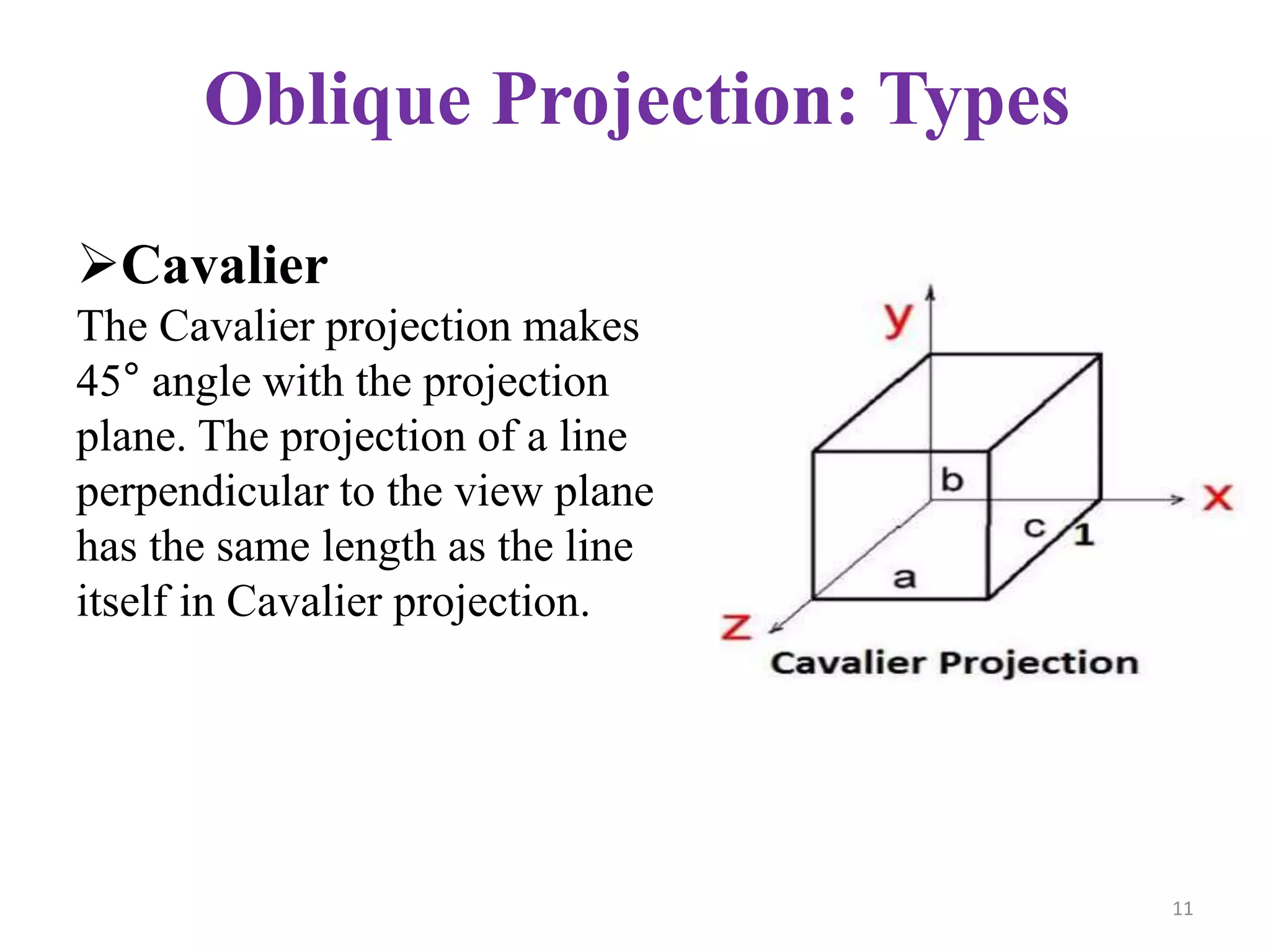
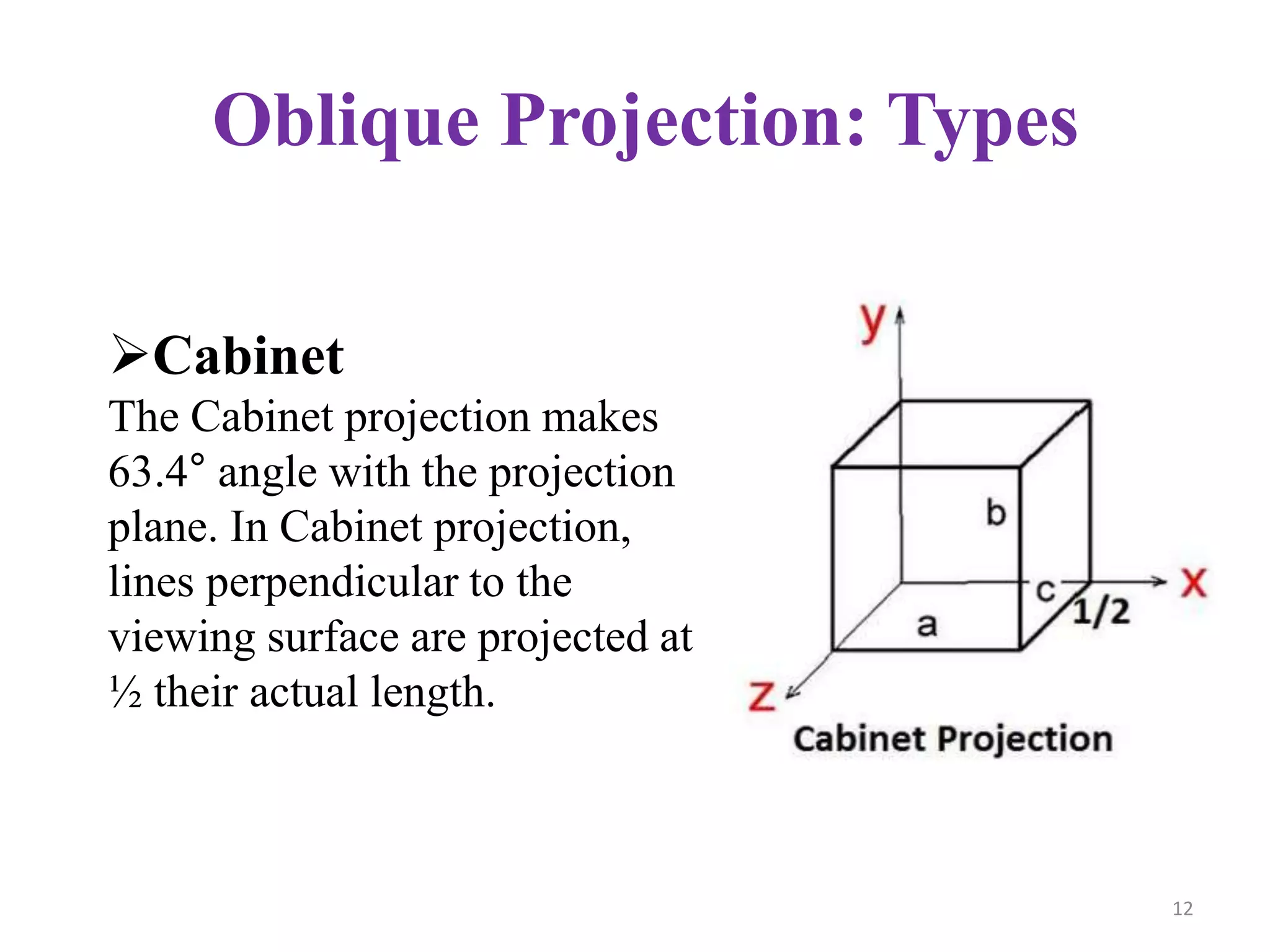
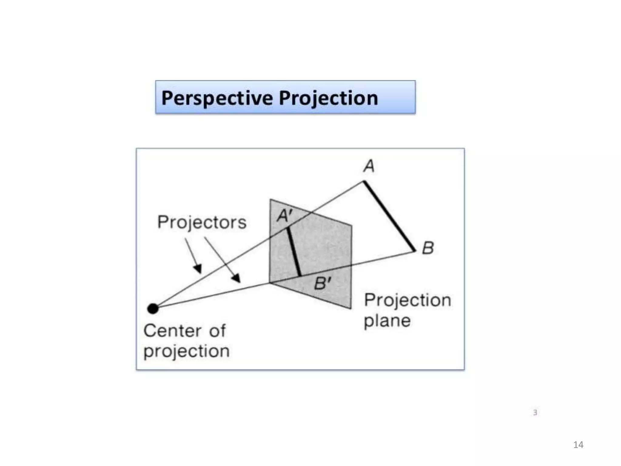
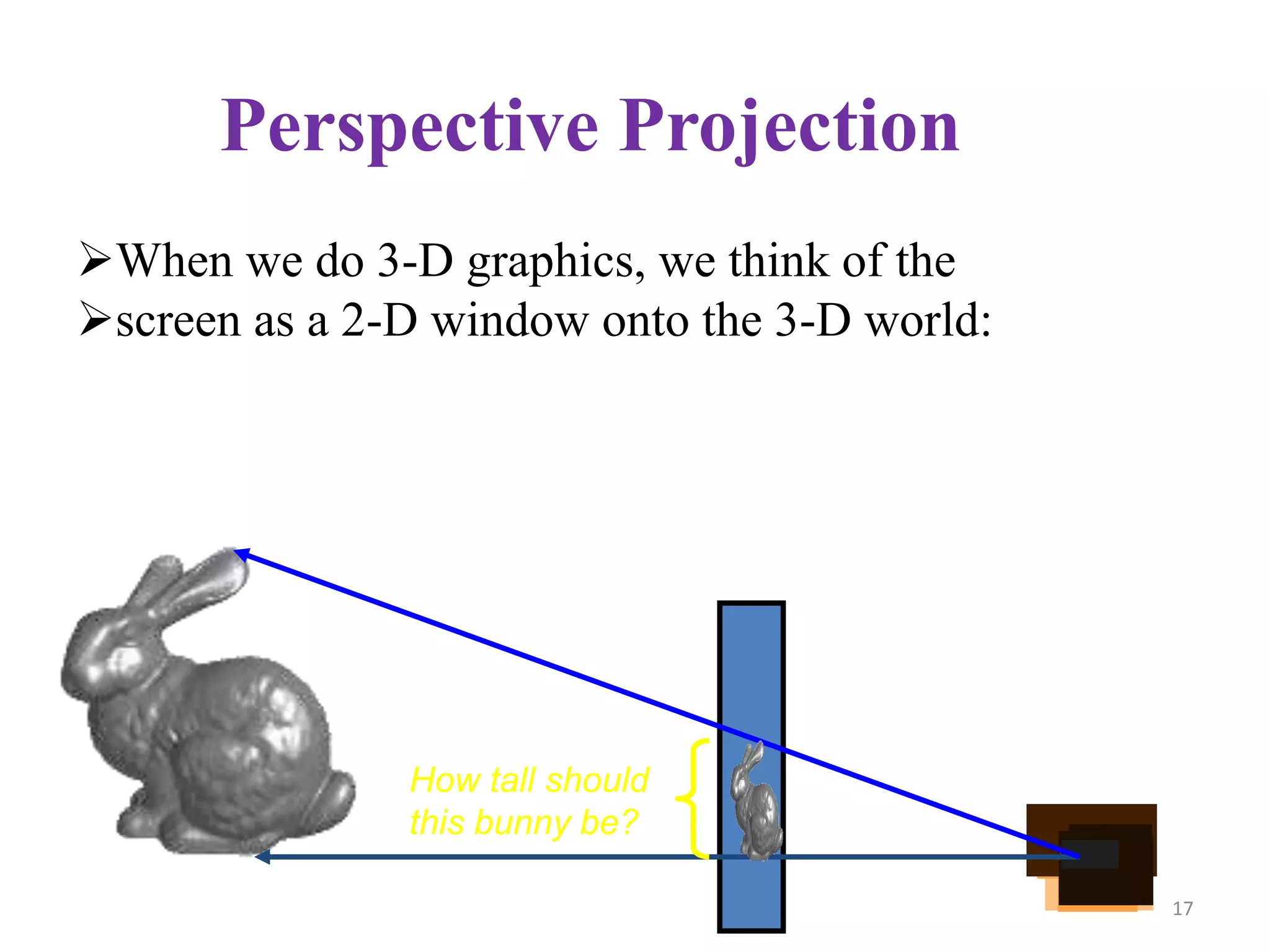
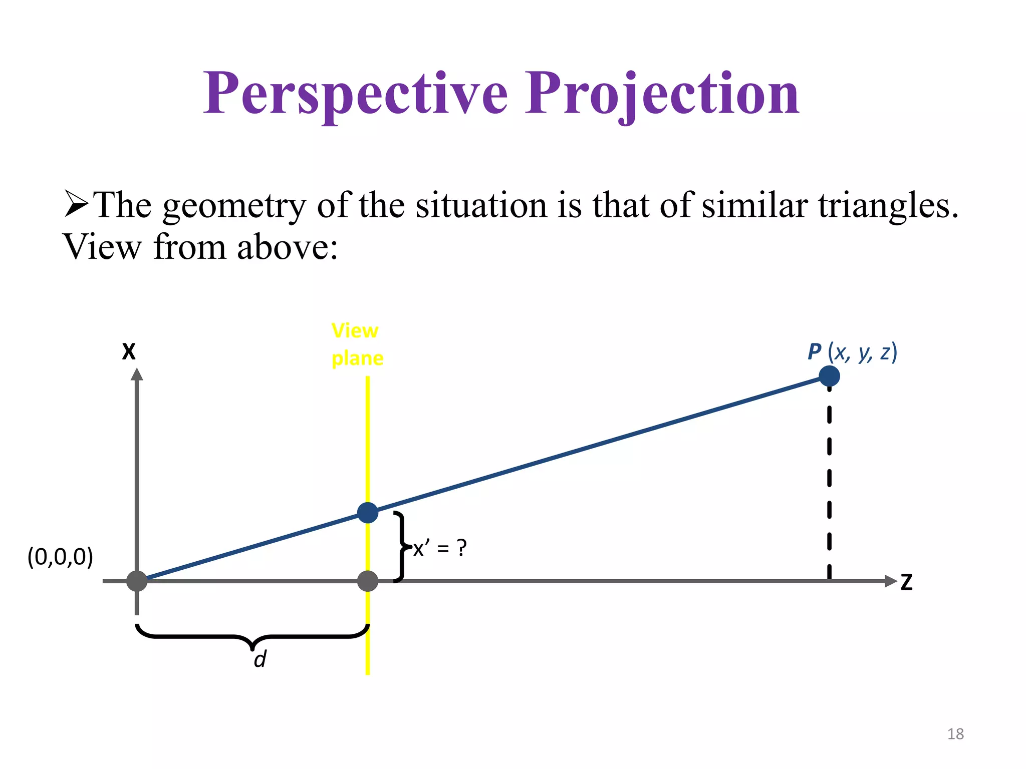
3D Display Methods
1
Contents
3D Display
Definition & Types
Projection Types
Parallel Projection
Definition & Types
Perspective Projection
Definition & Types
Depth Cueing
Visible Line & Surface Identification
Surface Rendering
2
3D Display Methods
•3D graphics deals with generating and displaying three
dimensional objects in a two-dimensional space(eg: display
screen).
•In addition to color and brightness, a 3-D pixels adds a
depth property that indicates where the point lies on the
imaginary z-axis.
•To generate realistic picture we have to first setup a
coordinate reference for camera. This co-ordinate reference
defines the position and orientation for the plane of the
camera.
3
•This plane used to
display a view of the
object
• Object description has
to transfer to the camera
reference co-ordinates
and projected onto the
selected display plane.
3D Display Methods Contd..
4
Types
5
Types of Projections
Transform 3D objects on to a 2D plane using
projections
2 types of projections
Perspective
Parallel
6
PROJECTIONS
PARALLEL
(parallel projectors)
PERSPECTIVE
(converging projectors)
One point
(one principal
vanishing point)
Two point
(Two principal
vanishing point)
Three point
(Three principal
vanishing point)
Orthographic
(projectors perpendicular
to view plane)
Oblique
(projectors not perpendicular to
view plane)
General
Cavalier
Cabinet
Multiview
(view plane parallel
to principal planes)
Axonometric
(view plane not parallel to
principal planes)
Isometric Dimetric Trimetric
7
Parallel Projection
Discards z-coordinate and parallel
lines from each vertex
Specify a direction of projection
instead of center of projection
Project points on the object
surface along parallel lines onto the
display plane.
Parallel lines are still parallel after
projection
8
1. Orthographic projection :
If the direction of projection
is perpendicular to the
projection plane then it is an
orthographic projection.
Parallel Projection: Types
9
2. Oblique projection : If the
direction of projection is not
perpendicular to the projection
plane then it is an oblique
projection.
Parallel Projection: Types
10
Cavalier
The Cavalier projection makes
45° angle with the projection
plane. The projection of a line
perpendicular to the view plane
has the same length as the line
itself in Cavalier projection.
Oblique Projection: Types
11
Cabinet
The Cabinet projection makes
63.4° angle with the projection
plane. In Cabinet projection,
lines perpendicular to the
viewing surface are projected at
½ their actual length.
Oblique Projection: Types
12
Perspective Projection
Project points to the display plane along converging
paths.
This is the way that our eyes and a camera lens form
images and so the displays are more realistic.
Parallel lines appear to converge to a distant point in
the background.
Distant objects appear smaller than objects closer to
the viewing position.
13
14
Types
One point perspective projection is simple to draw.
Two point perspective projection gives better
impression of depth.
Three point perspective projection is most difficult
to draw.
15
16
Perspective Projection
When we do 3-D graphics, we think of the
screen as a 2-D window onto the 3-D world:
How tall should
this bunny be?
17
Perspective Projection
The geometry of the situation is that of similar triangles.
View from above:
d
P (x, y, z)X
Z
View
plane
(0,0,0) x’ = ?
18
Perspective vs. Parallel
Perspective projection
Size varies inversely with distance - looks realistic
Distance and angles are not (in general) preserved
Parallel lines do not (in general) remain parallel
Parallel projection
Good for exact measurements
Parallel lines remain parallel
Angles are not (in general) preserved
Less realistic looking
19
Depth Cueing
To easily identify the front and back of display
objects.
Depth information can be included using various
methods.
A simple method to vary the intensity of objects
according to their distance from the viewing position.
Eg: lines closest to the viewing position are
displayed with the higher intensities and lines farther
away are displayed with lower intensities.
20
21
Visible Surface
Identification
22
Classification of Visible-Surface
Detection Algorithms
Mainly 2 types of approaches are followed
 Object-space methods
 Compares objects and parts of objects to each other
 Image-space methods
 Point by point at each pixel position on the projection
plane
23
Comparison Between Methods
 Object-space methods vs. Image-space
methods
 Object definition directly vs. their projected
images
 Most visible-surface algorithms use image-space
methods
 Object-space can be used effectively in some
cases
 Example: Line-display algorithms
24
Currently Most Used Approaches
Four algorithms:
Back-face elimination
Depth-buffer
Depth-sorting
Ray-casting
25
Surface
Rendering
26
Definition
Rendering is the process of generating an image from a
2D or 3D model (or models in what collectively could be
called a scene file) by means of computer programs.
Surface rendering involves the careful collection of data
on a given object in order to create a three-dimensional
image of that object on a computer. It is an important
technique used in a variety of industries.
One of the techniques to construct an image using
surface rendering is with illumination.
27
Uses:
Surface rendering is used in a number of industries,
such as in health care. There, parts of the body are
rendered so doctors can closely examine specific areas
of a patient or wounds they may have incurred.
Archaeologists also use rendering to make an image
of very fragile objects in order to examine them without
harming them.
28
Any Questions??
29
Thank You
30

3D Display

  • 1.
  • 2.
    Contents 3D Display Definition &Types Projection Types Parallel Projection Definition & Types Perspective Projection Definition & Types Depth Cueing Visible Line & Surface Identification Surface Rendering 2
  • 3.
    3D Display Methods •3Dgraphics deals with generating and displaying three dimensional objects in a two-dimensional space(eg: display screen). •In addition to color and brightness, a 3-D pixels adds a depth property that indicates where the point lies on the imaginary z-axis. •To generate realistic picture we have to first setup a coordinate reference for camera. This co-ordinate reference defines the position and orientation for the plane of the camera. 3
  • 4.
    •This plane usedto display a view of the object • Object description has to transfer to the camera reference co-ordinates and projected onto the selected display plane. 3D Display Methods Contd.. 4
  • 5.
  • 6.
    Types of Projections Transform3D objects on to a 2D plane using projections 2 types of projections Perspective Parallel 6
  • 7.
    PROJECTIONS PARALLEL (parallel projectors) PERSPECTIVE (converging projectors) Onepoint (one principal vanishing point) Two point (Two principal vanishing point) Three point (Three principal vanishing point) Orthographic (projectors perpendicular to view plane) Oblique (projectors not perpendicular to view plane) General Cavalier Cabinet Multiview (view plane parallel to principal planes) Axonometric (view plane not parallel to principal planes) Isometric Dimetric Trimetric 7
  • 8.
    Parallel Projection Discards z-coordinateand parallel lines from each vertex Specify a direction of projection instead of center of projection Project points on the object surface along parallel lines onto the display plane. Parallel lines are still parallel after projection 8
  • 9.
    1. Orthographic projection: If the direction of projection is perpendicular to the projection plane then it is an orthographic projection. Parallel Projection: Types 9
  • 10.
    2. Oblique projection: If the direction of projection is not perpendicular to the projection plane then it is an oblique projection. Parallel Projection: Types 10
  • 11.
    Cavalier The Cavalier projectionmakes 45° angle with the projection plane. The projection of a line perpendicular to the view plane has the same length as the line itself in Cavalier projection. Oblique Projection: Types 11
  • 12.
    Cabinet The Cabinet projectionmakes 63.4° angle with the projection plane. In Cabinet projection, lines perpendicular to the viewing surface are projected at ½ their actual length. Oblique Projection: Types 12
  • 13.
    Perspective Projection Project pointsto the display plane along converging paths. This is the way that our eyes and a camera lens form images and so the displays are more realistic. Parallel lines appear to converge to a distant point in the background. Distant objects appear smaller than objects closer to the viewing position. 13
  • 14.
  • 15.
    Types One point perspectiveprojection is simple to draw. Two point perspective projection gives better impression of depth. Three point perspective projection is most difficult to draw. 15
  • 16.
  • 17.
    Perspective Projection When wedo 3-D graphics, we think of the screen as a 2-D window onto the 3-D world: How tall should this bunny be? 17
  • 18.
    Perspective Projection The geometryof the situation is that of similar triangles. View from above: d P (x, y, z)X Z View plane (0,0,0) x’ = ? 18
  • 19.
    Perspective vs. Parallel Perspectiveprojection Size varies inversely with distance - looks realistic Distance and angles are not (in general) preserved Parallel lines do not (in general) remain parallel Parallel projection Good for exact measurements Parallel lines remain parallel Angles are not (in general) preserved Less realistic looking 19
  • 20.
    Depth Cueing To easilyidentify the front and back of display objects. Depth information can be included using various methods. A simple method to vary the intensity of objects according to their distance from the viewing position. Eg: lines closest to the viewing position are displayed with the higher intensities and lines farther away are displayed with lower intensities. 20
  • 21.
  • 22.
  • 23.
    Classification of Visible-Surface DetectionAlgorithms Mainly 2 types of approaches are followed  Object-space methods  Compares objects and parts of objects to each other  Image-space methods  Point by point at each pixel position on the projection plane 23
  • 24.
    Comparison Between Methods Object-space methods vs. Image-space methods  Object definition directly vs. their projected images  Most visible-surface algorithms use image-space methods  Object-space can be used effectively in some cases  Example: Line-display algorithms 24
  • 25.
    Currently Most UsedApproaches Four algorithms: Back-face elimination Depth-buffer Depth-sorting Ray-casting 25
  • 26.
  • 27.
    Definition Rendering is theprocess of generating an image from a 2D or 3D model (or models in what collectively could be called a scene file) by means of computer programs. Surface rendering involves the careful collection of data on a given object in order to create a three-dimensional image of that object on a computer. It is an important technique used in a variety of industries. One of the techniques to construct an image using surface rendering is with illumination. 27
  • 28.
    Uses: Surface rendering isused in a number of industries, such as in health care. There, parts of the body are rendered so doctors can closely examine specific areas of a patient or wounds they may have incurred. Archaeologists also use rendering to make an image of very fragile objects in order to examine them without harming them. 28
  • 29.
  • 30.