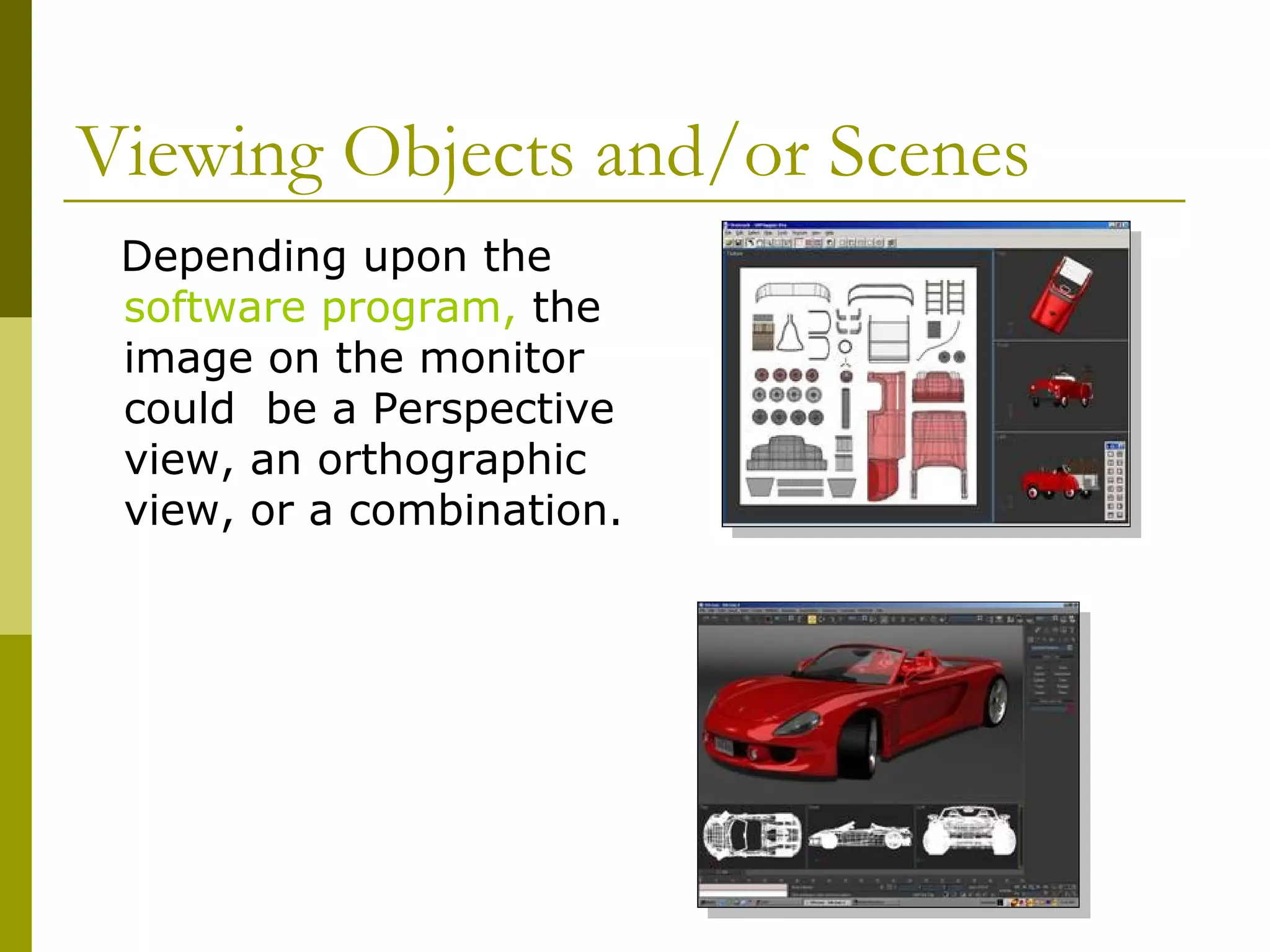
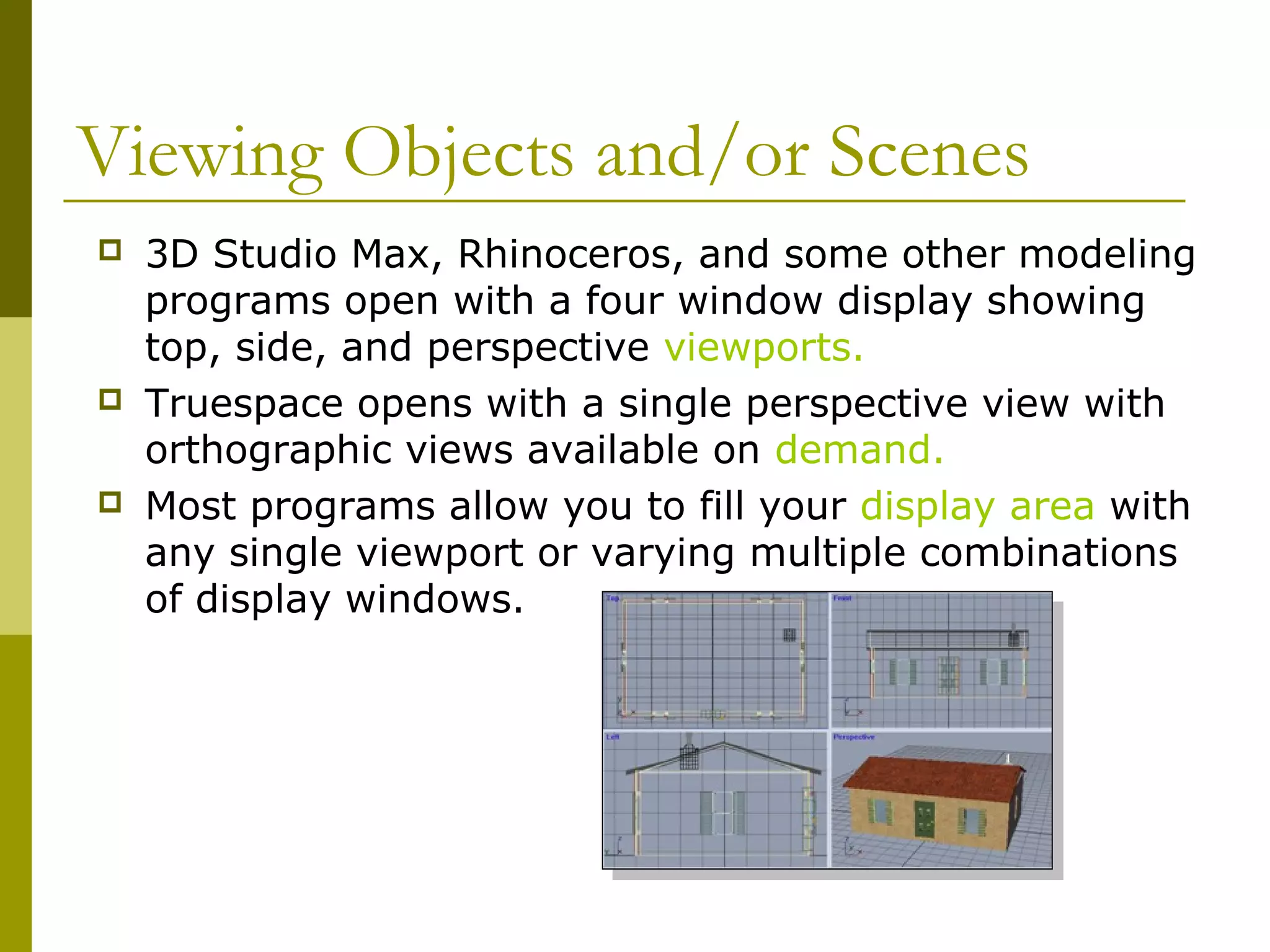
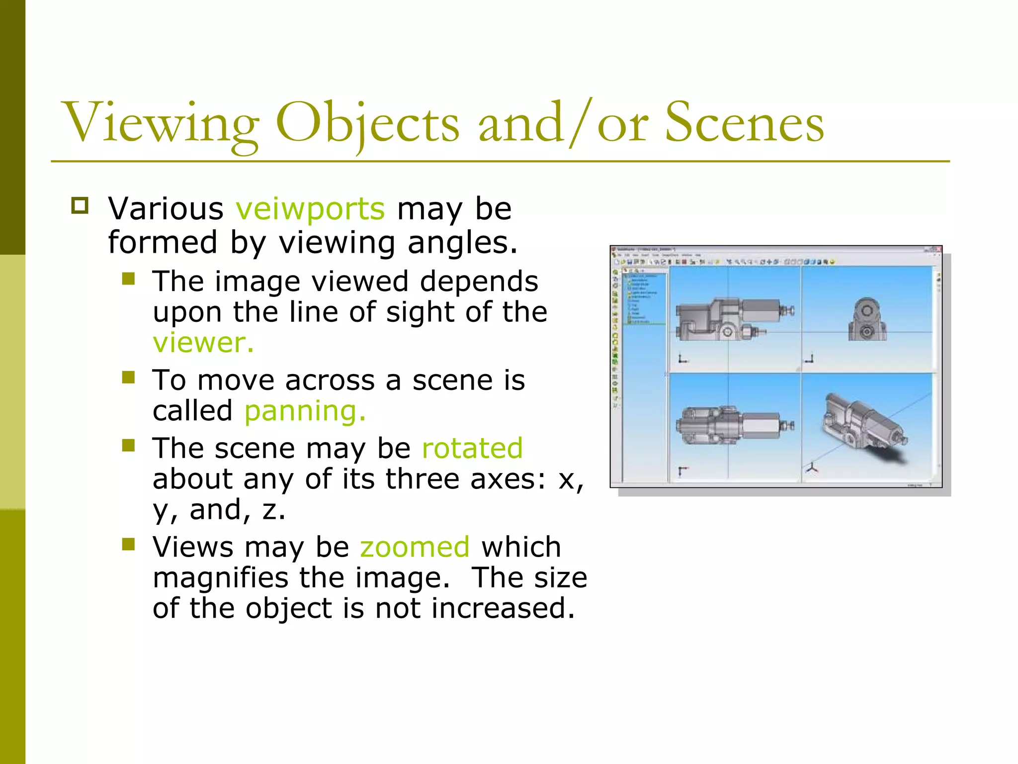
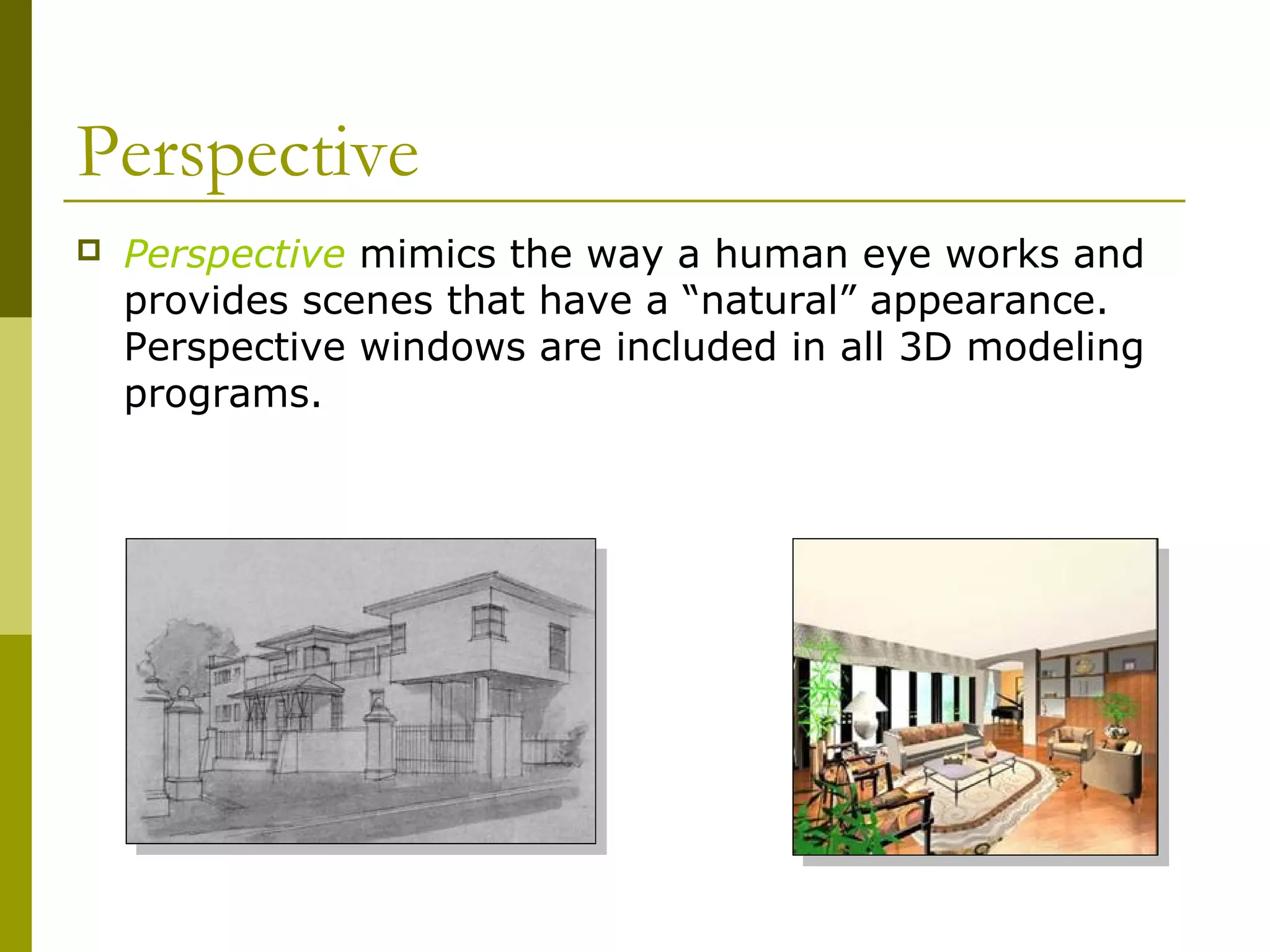
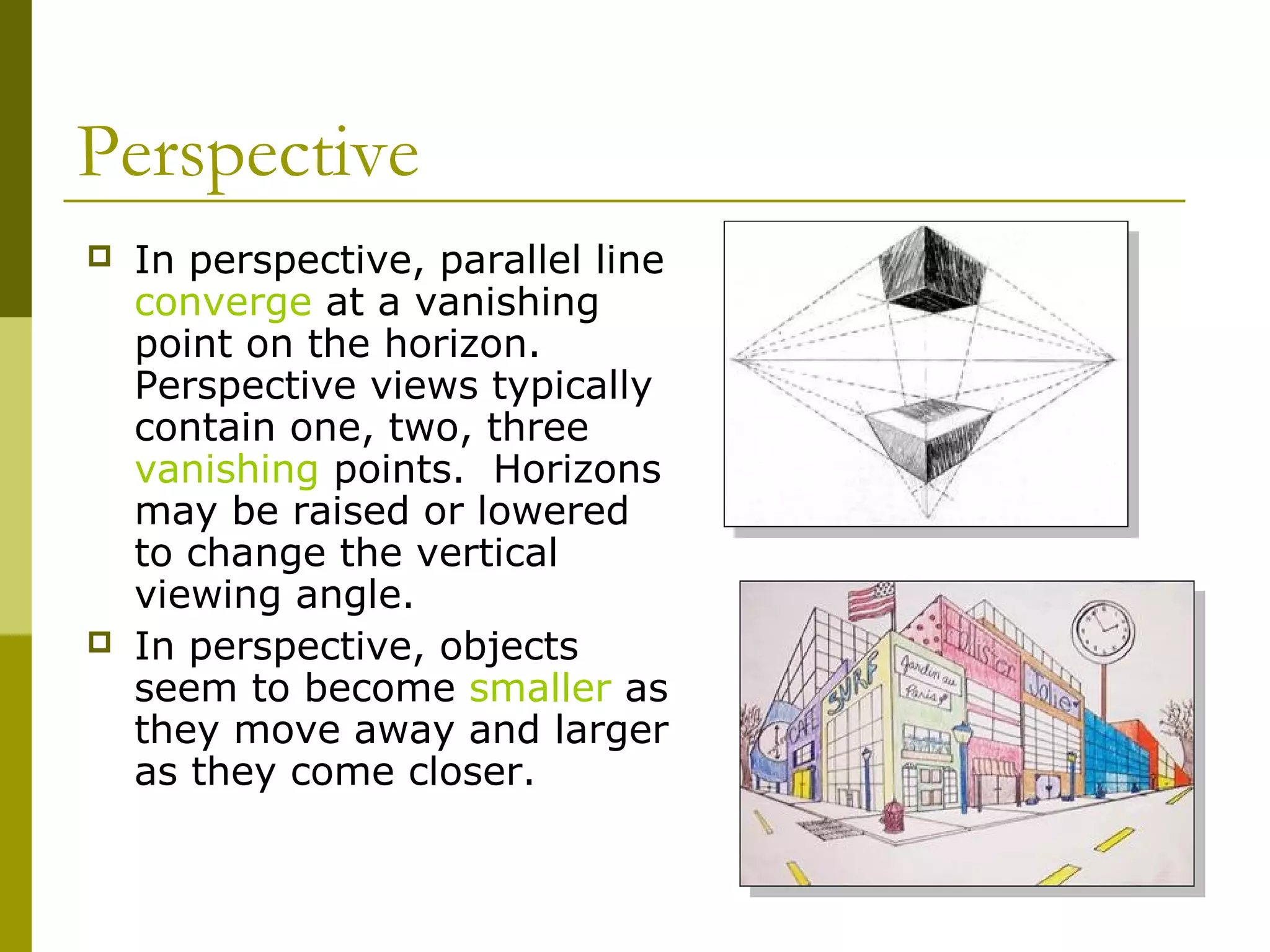
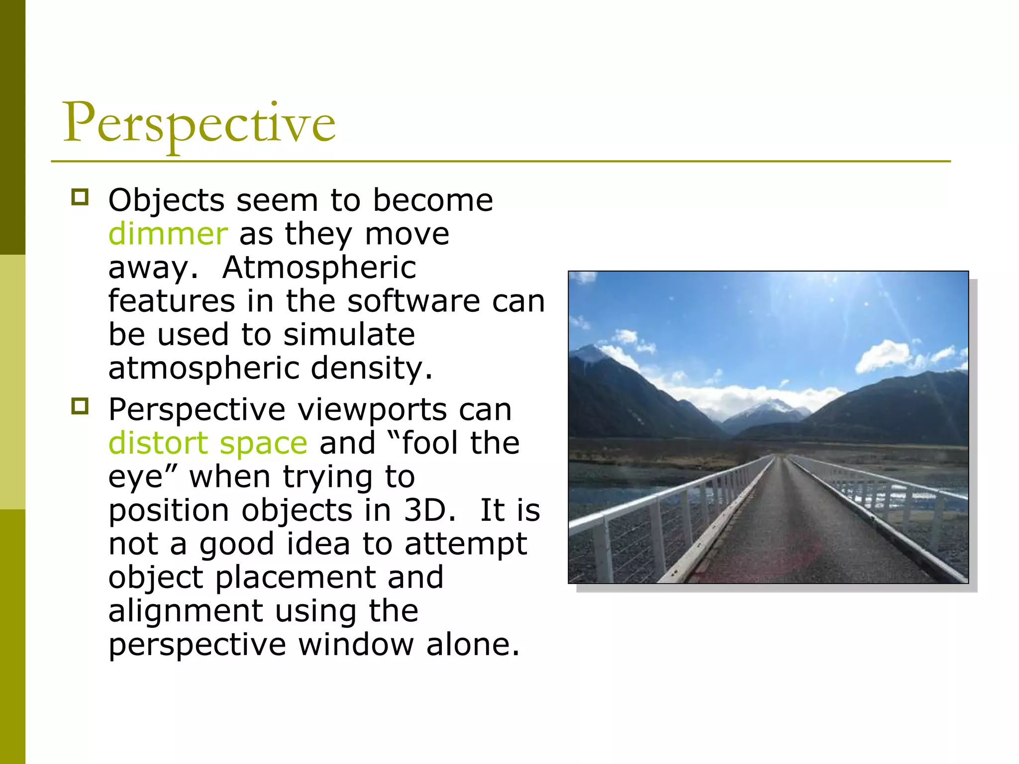
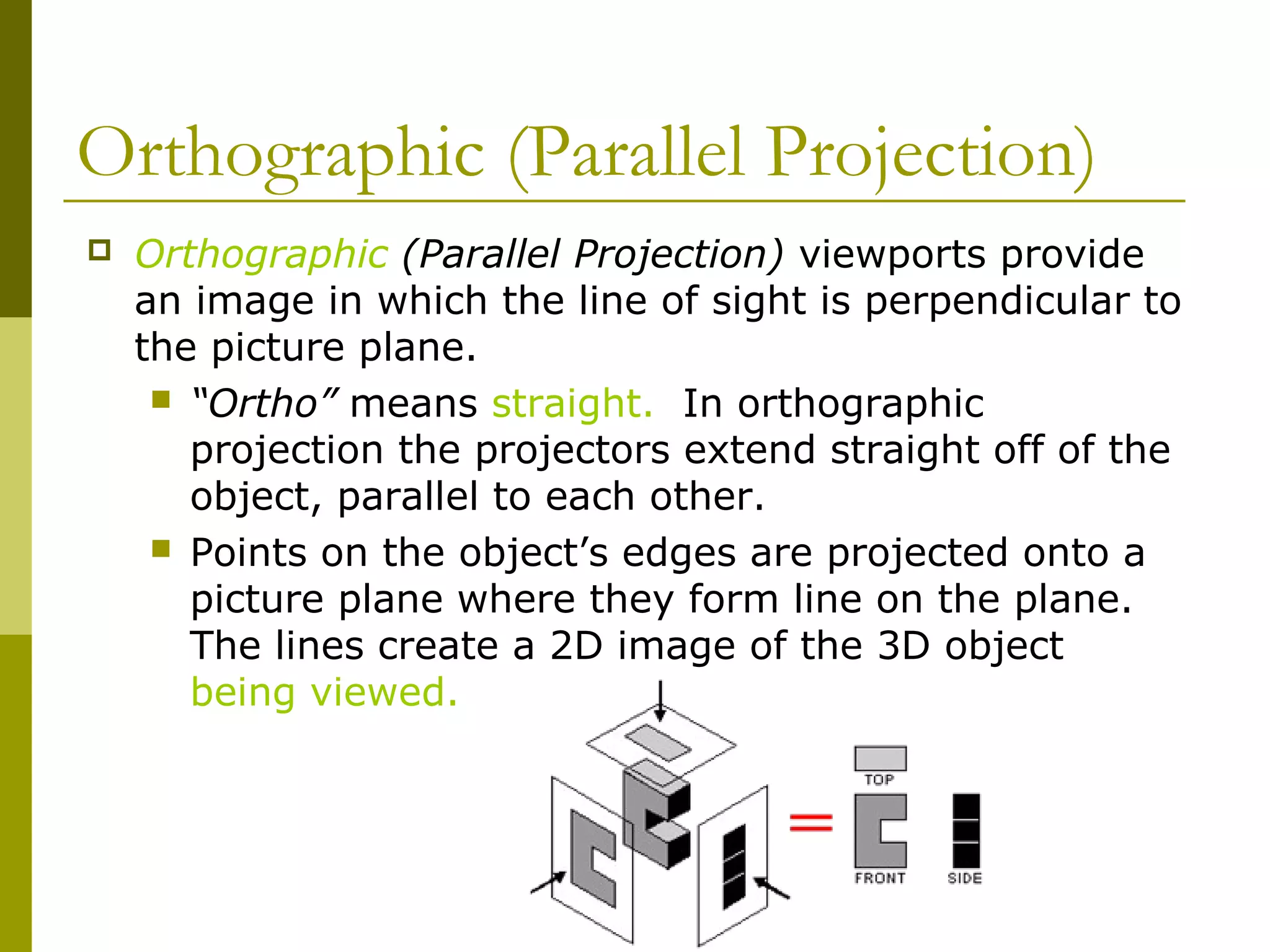
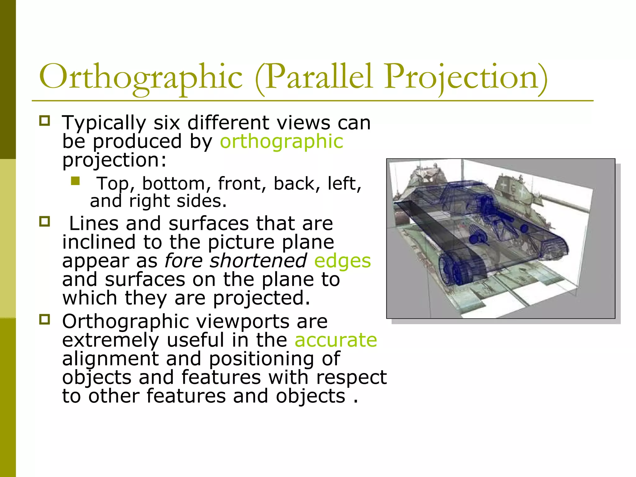
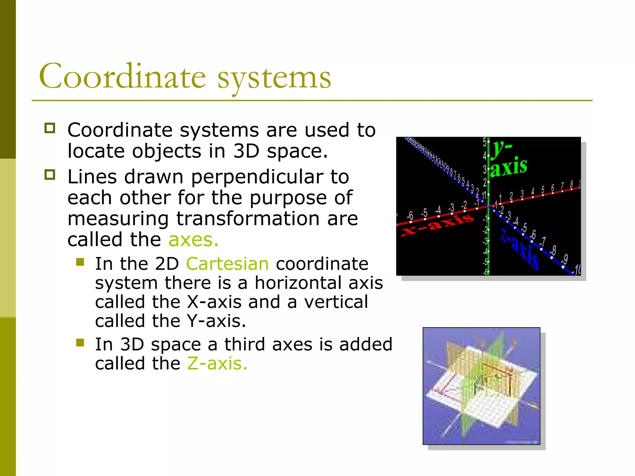
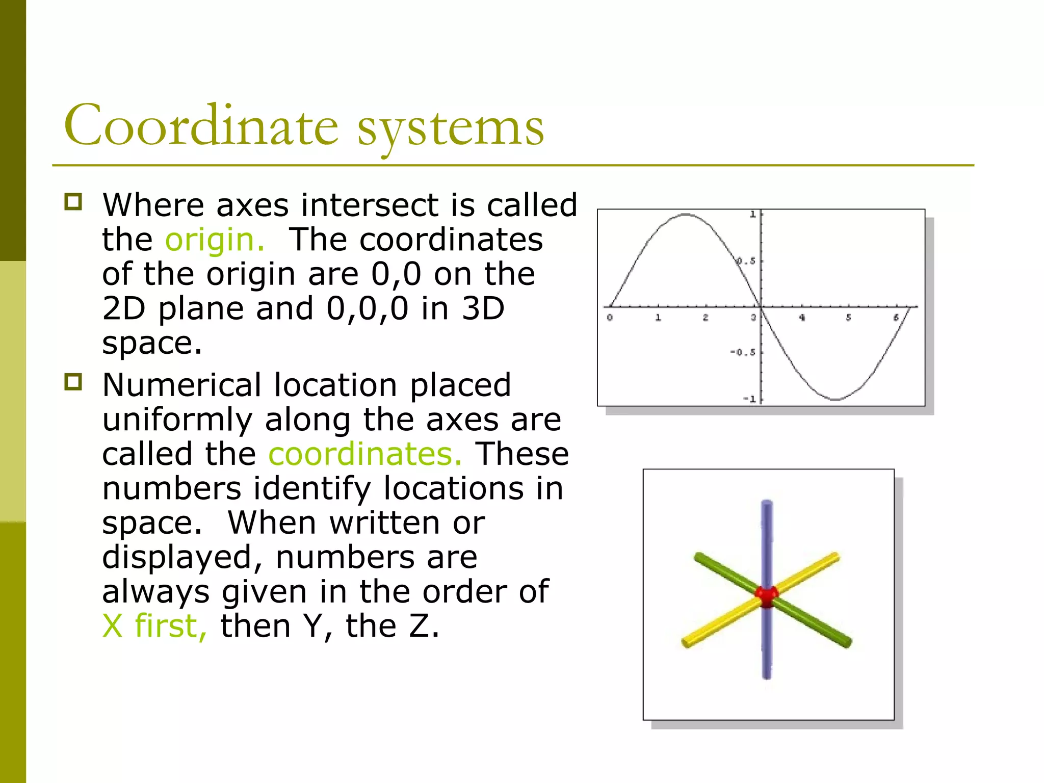
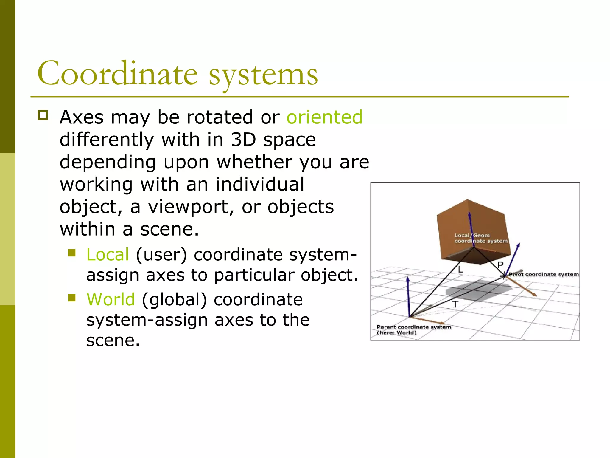
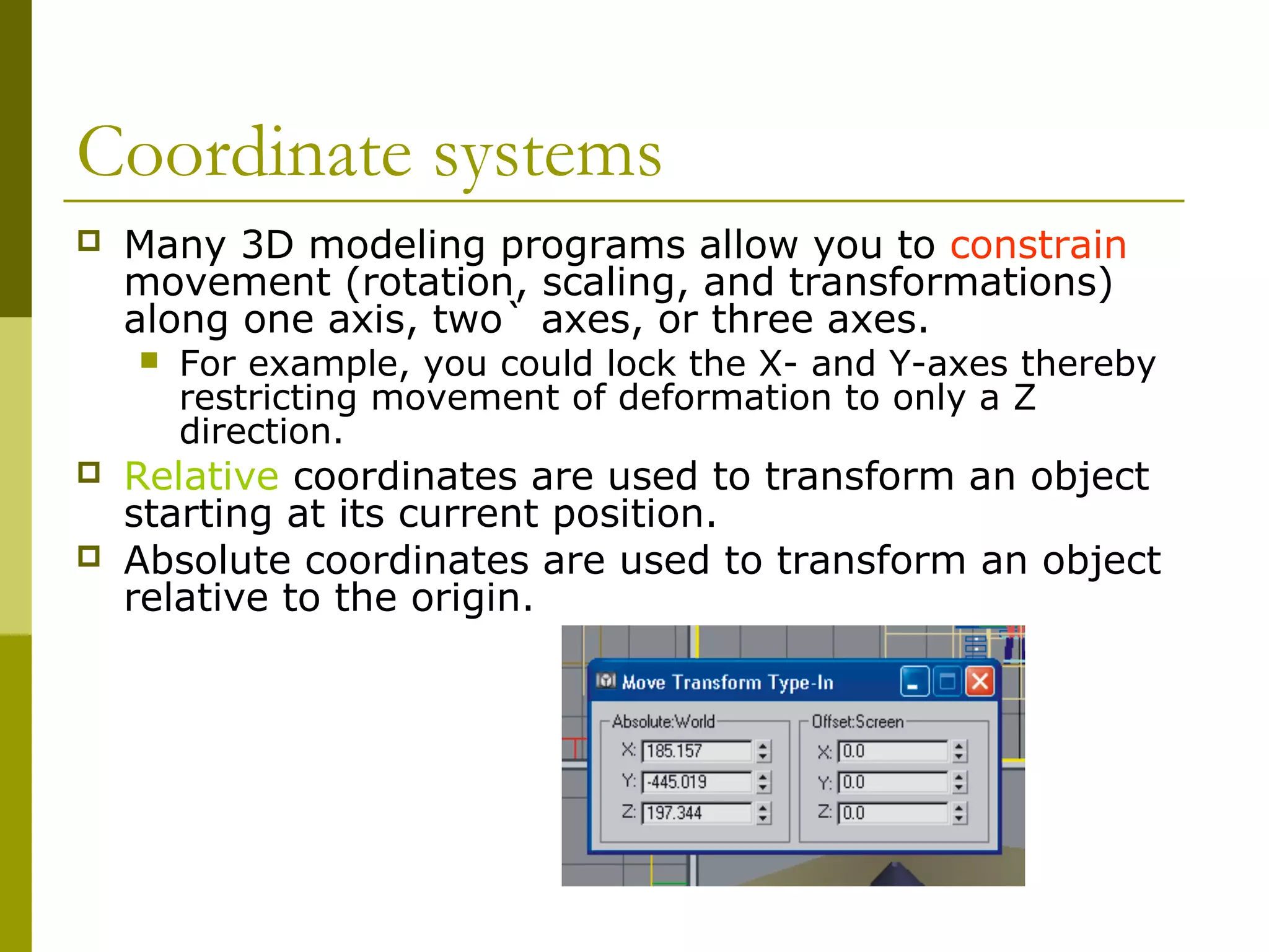
Navigating in 3D MAX
   Guilford County SciVis
      V106.02 part 1
Viewing Objects and/or Scenes
 Depending upon the
 software program, the
 image on the monitor
 could be a Perspective
 view, an orthographic
 view, or a combination.
Viewing Objects and/or Scenes
   3D Studio Max, Rhinoceros, and some other modeling
    programs open with a four window display showing
    top, side, and perspective viewports.
   Truespace opens with a single perspective view with
    orthographic views available on demand.
   Most programs allow you to fill your display area with
    any single viewport or varying multiple combinations
    of display windows.
Viewing Objects and/or Scenes
   Various veiwports may be
    formed by viewing angles.
       The image viewed depends
        upon the line of sight of the
        viewer.
       To move across a scene is
        called panning.
       The scene may be rotated
        about any of its three axes: x,
        y, and, z.
       Views may be zoomed which
        magnifies the image. The size
        of the object is not increased.
Perspective
   Perspective mimics the way a human eye works and
    provides scenes that have a “natural” appearance.
    Perspective windows are included in all 3D modeling
    programs.
Perspective
   In perspective, parallel line
    converge at a vanishing
    point on the horizon.
    Perspective views typically
    contain one, two, three
    vanishing points. Horizons
    may be raised or lowered
    to change the vertical
    viewing angle.
   In perspective, objects
    seem to become smaller as
    they move away and larger
    as they come closer.
Perspective
   Objects seem to become
    dimmer as they move
    away. Atmospheric
    features in the software can
    be used to simulate
    atmospheric density.
   Perspective viewports can
    distort space and “fool the
    eye” when trying to
    position objects in 3D. It is
    not a good idea to attempt
    object placement and
    alignment using the
    perspective window alone.
Orthographic (Parallel Projection)
   Orthographic (Parallel Projection) viewports provide
    an image in which the line of sight is perpendicular to
    the picture plane.
      “Ortho” means straight. In orthographic
       projection the projectors extend straight off of the
       object, parallel to each other.
      Points on the object’s edges are projected onto a
       picture plane where they form line on the plane.
       The lines create a 2D image of the 3D object
       being viewed.
Orthographic (Parallel Projection)
   Typically six different views can
    be produced by orthographic
    projection:
        Top, bottom, front, back, left,
        and right sides.
    Lines and surfaces that are
    inclined to the picture plane
    appear as fore shortened edges
    and surfaces on the plane to
    which they are projected.
   Orthographic viewports are
    extremely useful in the accurate
    alignment and positioning of
    objects and features with respect
    to other features and objects .
Coordinate systems
   Coordinate systems are used to
    locate objects in 3D space.
   Lines drawn perpendicular to
    each other for the purpose of
    measuring transformation are
    called the axes.
       In the 2D Cartesian coordinate
        system there is a horizontal axis
        called the X-axis and a vertical
        called the Y-axis.
       In 3D space a third axes is added
        called the Z-axis.
Coordinate systems
   Where axes intersect is called
    the origin. The coordinates
    of the origin are 0,0 on the
    2D plane and 0,0,0 in 3D
    space.
   Numerical location placed
    uniformly along the axes are
    called the coordinates. These
    numbers identify locations in
    space. When written or
    displayed, numbers are
    always given in the order of
    X first, then Y, the Z.
Coordinate systems
   Axes may be rotated or oriented
    differently with in 3D space
    depending upon whether you are
    working with an individual
    object, a viewport, or objects
    within a scene.
       Local (user) coordinate system-
        assign axes to particular object.
       World (global) coordinate
        system-assign axes to the
        scene.
Coordinate systems
   Many 3D modeling programs allow you to constrain
    movement (rotation, scaling, and transformations)
    along one axis, two` axes, or three axes.
       For example, you could lock the X- and Y-axes thereby
        restricting movement of deformation to only a Z
        direction.
   Relative coordinates are used to transform an object
    starting at its current position.
   Absolute coordinates are used to transform an object
    relative to the origin.
End Part I

3 d modeling part 1

  • 1.
    Navigating in 3DMAX Guilford County SciVis V106.02 part 1
  • 2.
    Viewing Objects and/orScenes Depending upon the software program, the image on the monitor could be a Perspective view, an orthographic view, or a combination.
  • 3.
    Viewing Objects and/orScenes  3D Studio Max, Rhinoceros, and some other modeling programs open with a four window display showing top, side, and perspective viewports.  Truespace opens with a single perspective view with orthographic views available on demand.  Most programs allow you to fill your display area with any single viewport or varying multiple combinations of display windows.
  • 4.
    Viewing Objects and/orScenes  Various veiwports may be formed by viewing angles.  The image viewed depends upon the line of sight of the viewer.  To move across a scene is called panning.  The scene may be rotated about any of its three axes: x, y, and, z.  Views may be zoomed which magnifies the image. The size of the object is not increased.
  • 5.
    Perspective  Perspective mimics the way a human eye works and provides scenes that have a “natural” appearance. Perspective windows are included in all 3D modeling programs.
  • 6.
    Perspective  In perspective, parallel line converge at a vanishing point on the horizon. Perspective views typically contain one, two, three vanishing points. Horizons may be raised or lowered to change the vertical viewing angle.  In perspective, objects seem to become smaller as they move away and larger as they come closer.
  • 7.
    Perspective  Objects seem to become dimmer as they move away. Atmospheric features in the software can be used to simulate atmospheric density.  Perspective viewports can distort space and “fool the eye” when trying to position objects in 3D. It is not a good idea to attempt object placement and alignment using the perspective window alone.
  • 8.
    Orthographic (Parallel Projection)  Orthographic (Parallel Projection) viewports provide an image in which the line of sight is perpendicular to the picture plane.  “Ortho” means straight. In orthographic projection the projectors extend straight off of the object, parallel to each other.  Points on the object’s edges are projected onto a picture plane where they form line on the plane. The lines create a 2D image of the 3D object being viewed.
  • 9.
    Orthographic (Parallel Projection)  Typically six different views can be produced by orthographic projection:  Top, bottom, front, back, left, and right sides.  Lines and surfaces that are inclined to the picture plane appear as fore shortened edges and surfaces on the plane to which they are projected.  Orthographic viewports are extremely useful in the accurate alignment and positioning of objects and features with respect to other features and objects .
  • 10.
    Coordinate systems  Coordinate systems are used to locate objects in 3D space.  Lines drawn perpendicular to each other for the purpose of measuring transformation are called the axes.  In the 2D Cartesian coordinate system there is a horizontal axis called the X-axis and a vertical called the Y-axis.  In 3D space a third axes is added called the Z-axis.
  • 11.
    Coordinate systems  Where axes intersect is called the origin. The coordinates of the origin are 0,0 on the 2D plane and 0,0,0 in 3D space.  Numerical location placed uniformly along the axes are called the coordinates. These numbers identify locations in space. When written or displayed, numbers are always given in the order of X first, then Y, the Z.
  • 12.
    Coordinate systems  Axes may be rotated or oriented differently with in 3D space depending upon whether you are working with an individual object, a viewport, or objects within a scene.  Local (user) coordinate system- assign axes to particular object.  World (global) coordinate system-assign axes to the scene.
  • 13.
    Coordinate systems  Many 3D modeling programs allow you to constrain movement (rotation, scaling, and transformations) along one axis, two` axes, or three axes.  For example, you could lock the X- and Y-axes thereby restricting movement of deformation to only a Z direction.  Relative coordinates are used to transform an object starting at its current position.  Absolute coordinates are used to transform an object relative to the origin.
  • 14.