Downloaded 90 times

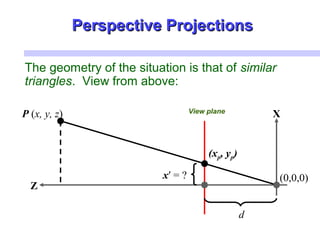
![Desired result for a point [x, y, z, 1]T
projected
onto the view plane:
dz
dz
y
z
yd
y
dz
x
z
xd
x
z
y
d
y
z
x
d
x
==
⋅
==
⋅
=
==
',','
'
,
'
Perspective ProjectionsPerspective Projections](https://image.slidesharecdn.com/threedimensionalconcepts-181123102719/85/Three-dimensional-concepts-Computer-Graphics-39-320.jpg)
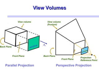
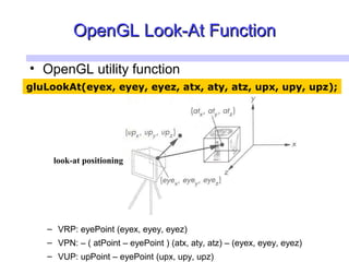
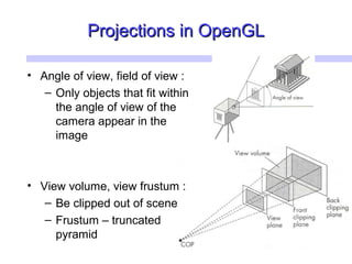
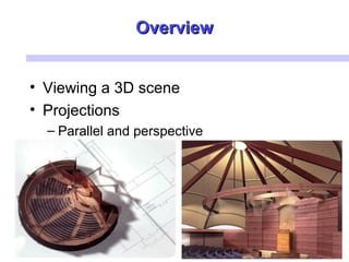
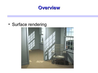
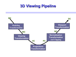
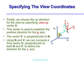
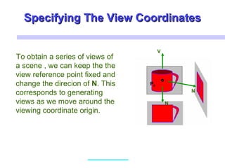
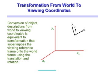
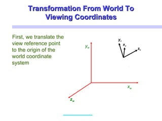
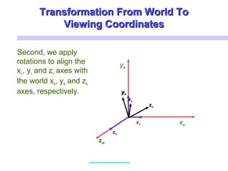
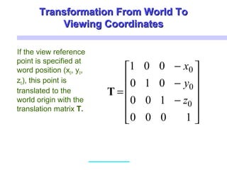
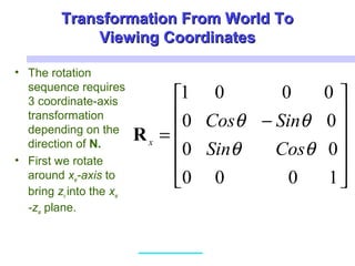
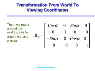
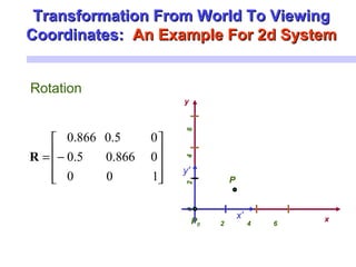
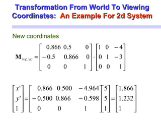
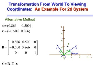
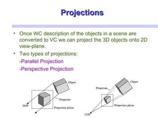
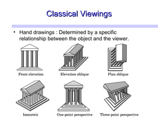
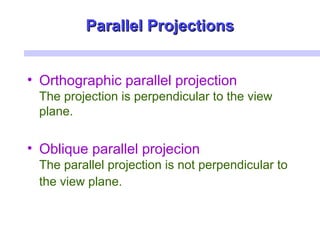
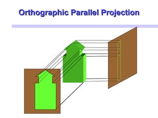
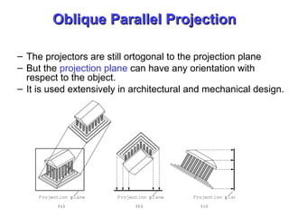
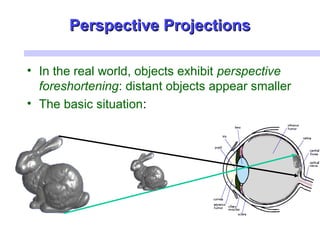
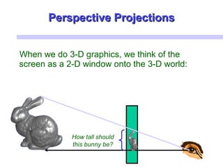
Three key points about advanced computer graphics and 3D viewing: 1. 3D viewing involves establishing a viewing coordinate system and transforming 3D world coordinates to 2D viewing coordinates using translations and rotations. Projections like parallel and perspective then project the viewing coordinates onto a 2D view plane. 2. Common projections used in 3D viewing are parallel projections, which project lines parallel to the view plane, and perspective projections, which simulate how the human eye sees and cause objects to appear smaller with distance. 3. Viewing pipelines involve modeling, transformations between coordinate systems, projections, clipping to a view volume, and normalization before rendering the 2D image. Technologies like OpenGL help specify common operations like projections, view


![MODULE-5 notes [BCG402-CG&V] PART-B.pdf](https://cdn.slidesharecdn.com/ss_thumbnails/module-5notesbcg402-cgvpart-b-250630054728-c1eaacea-thumbnail.jpg?width=640&height=640&fit=bounds)