Downloaded 234 times

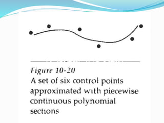

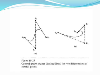
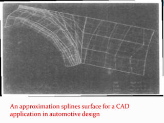

The document discusses spline representations, which are flexible strips used to create smooth curves through designated points. It explains the mathematical description of splines and their applications in computer graphics, such as in design, digitization, and animation paths. Additionally, it covers concepts of interpolation and approximation in constructing spline curves and surfaces, highlighting the importance of control points and convex hulls.