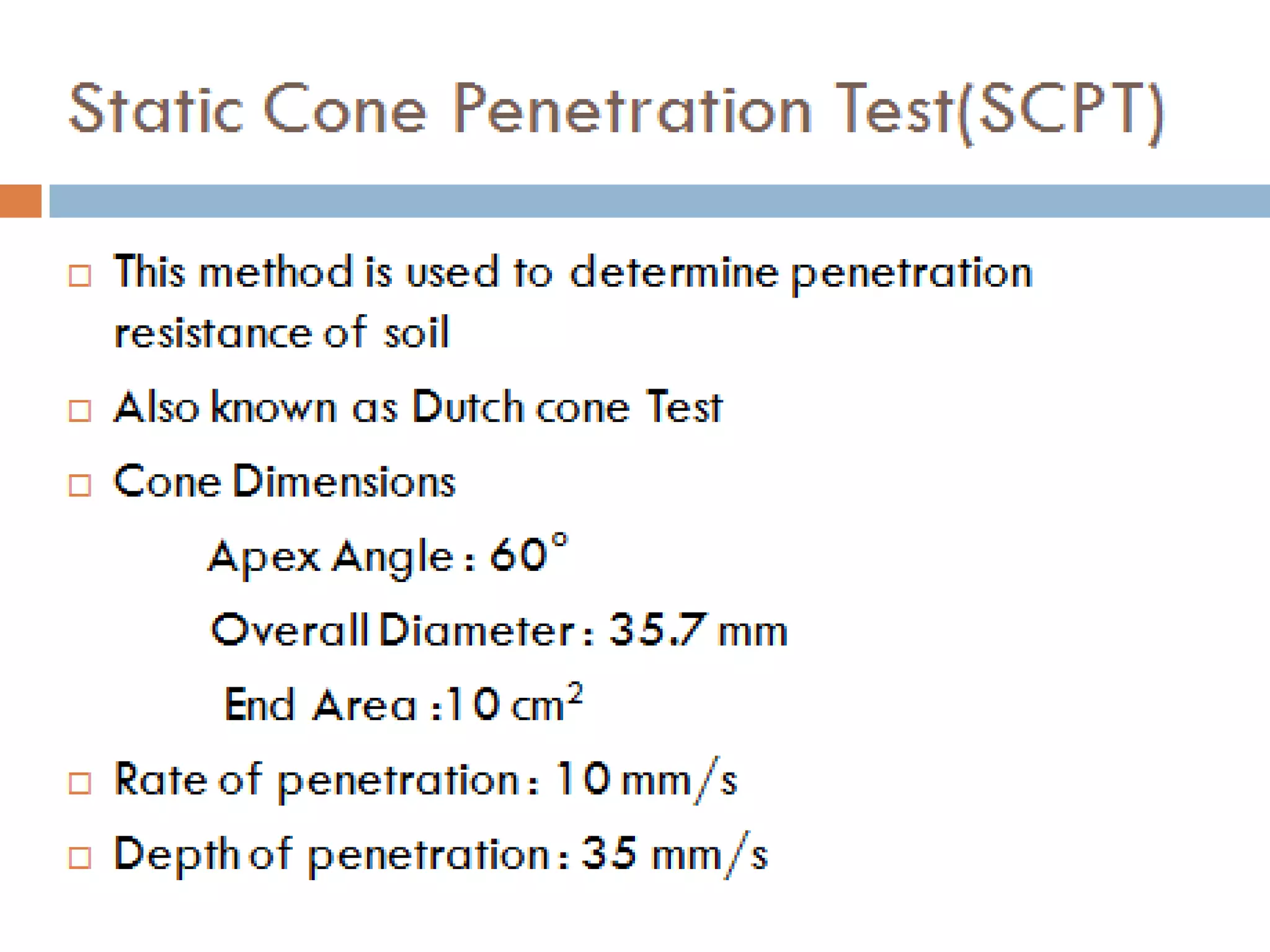
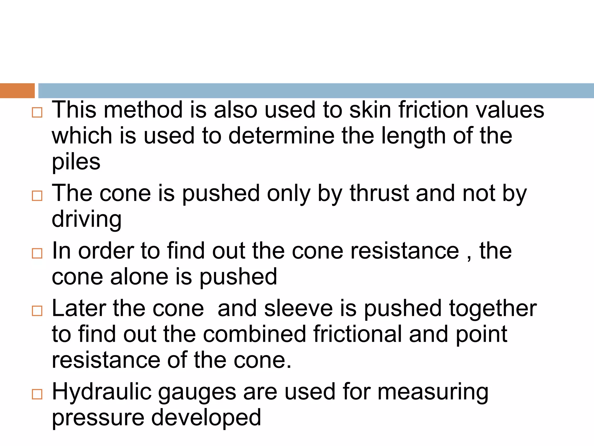
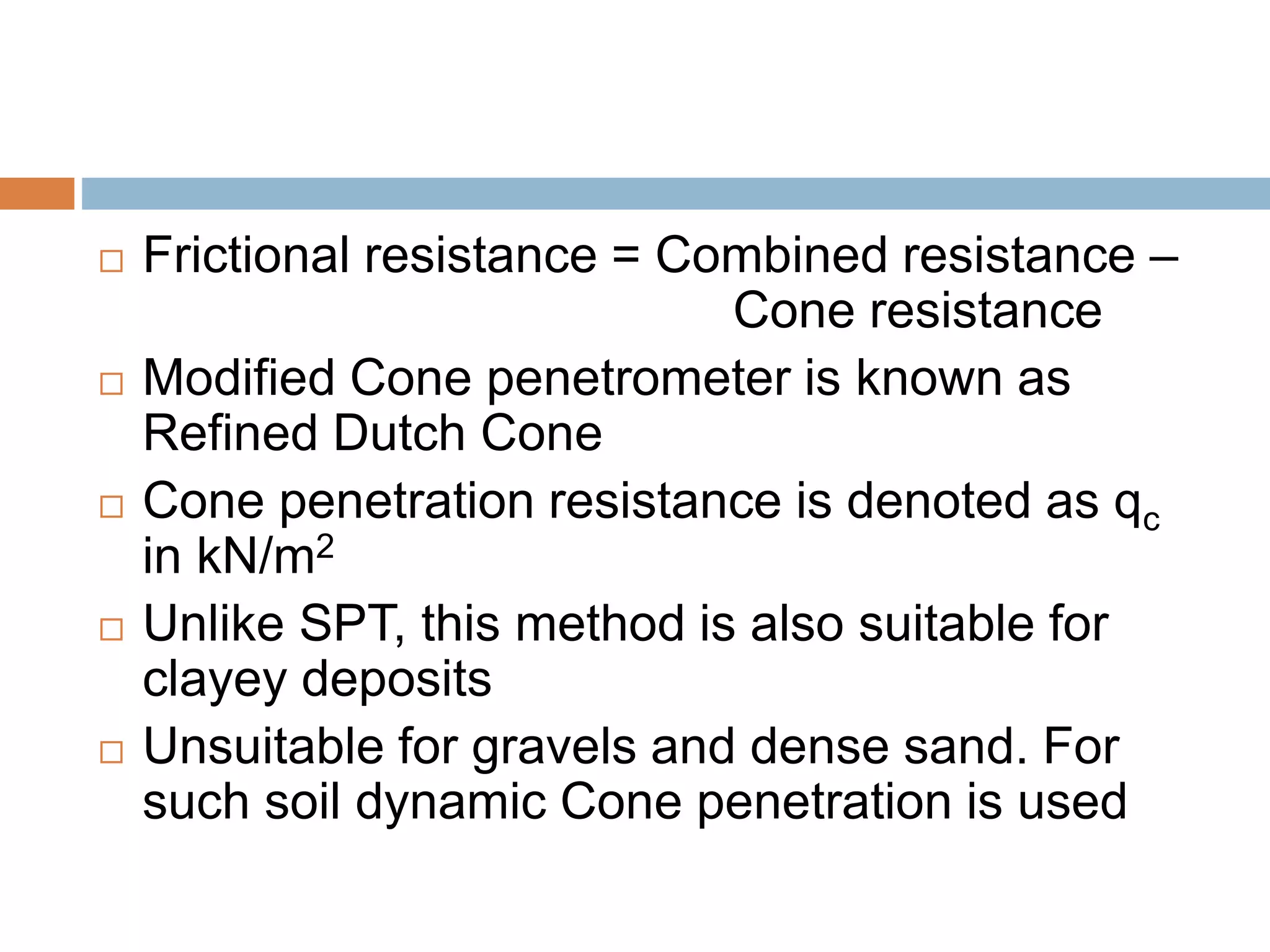
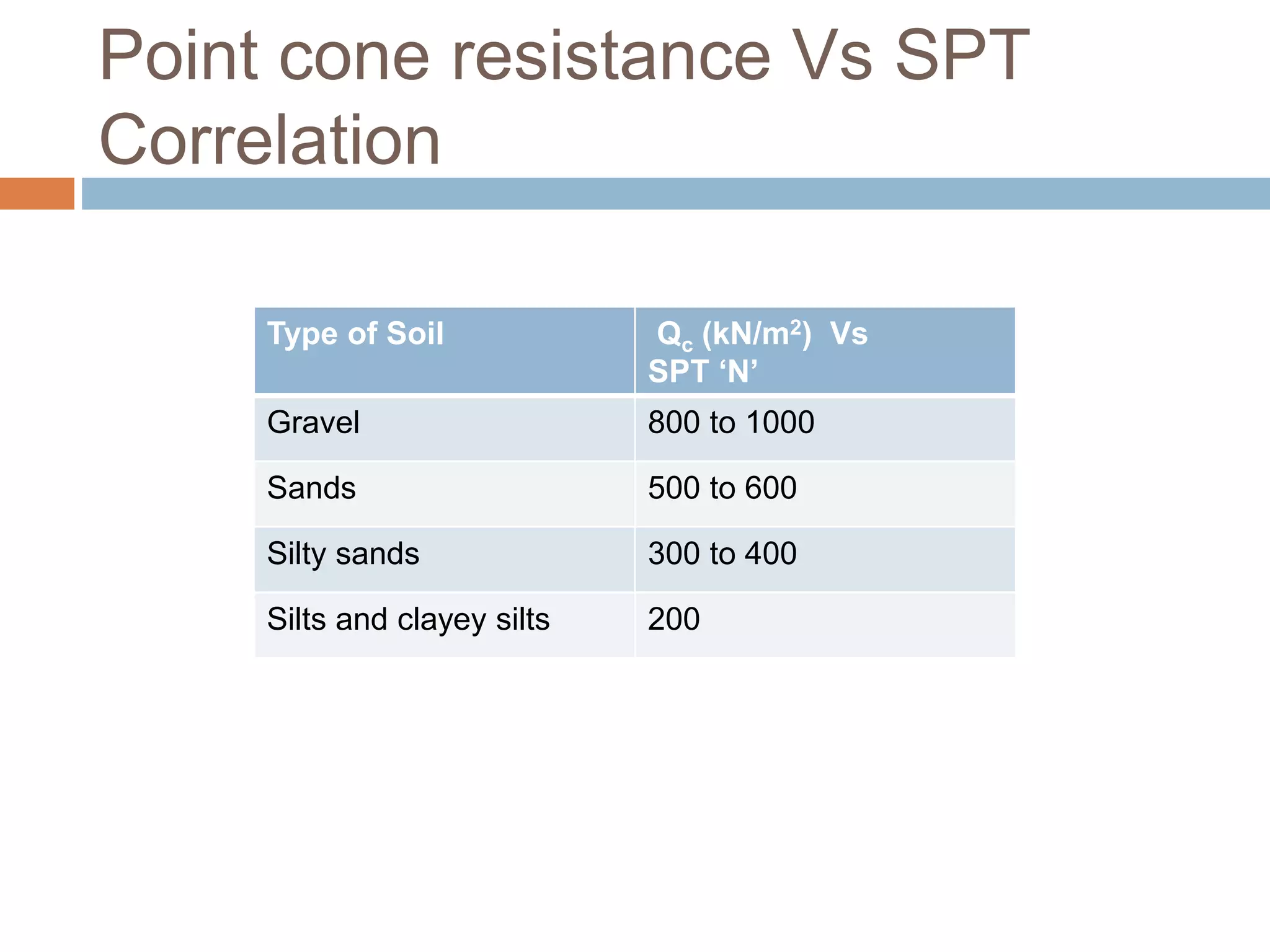
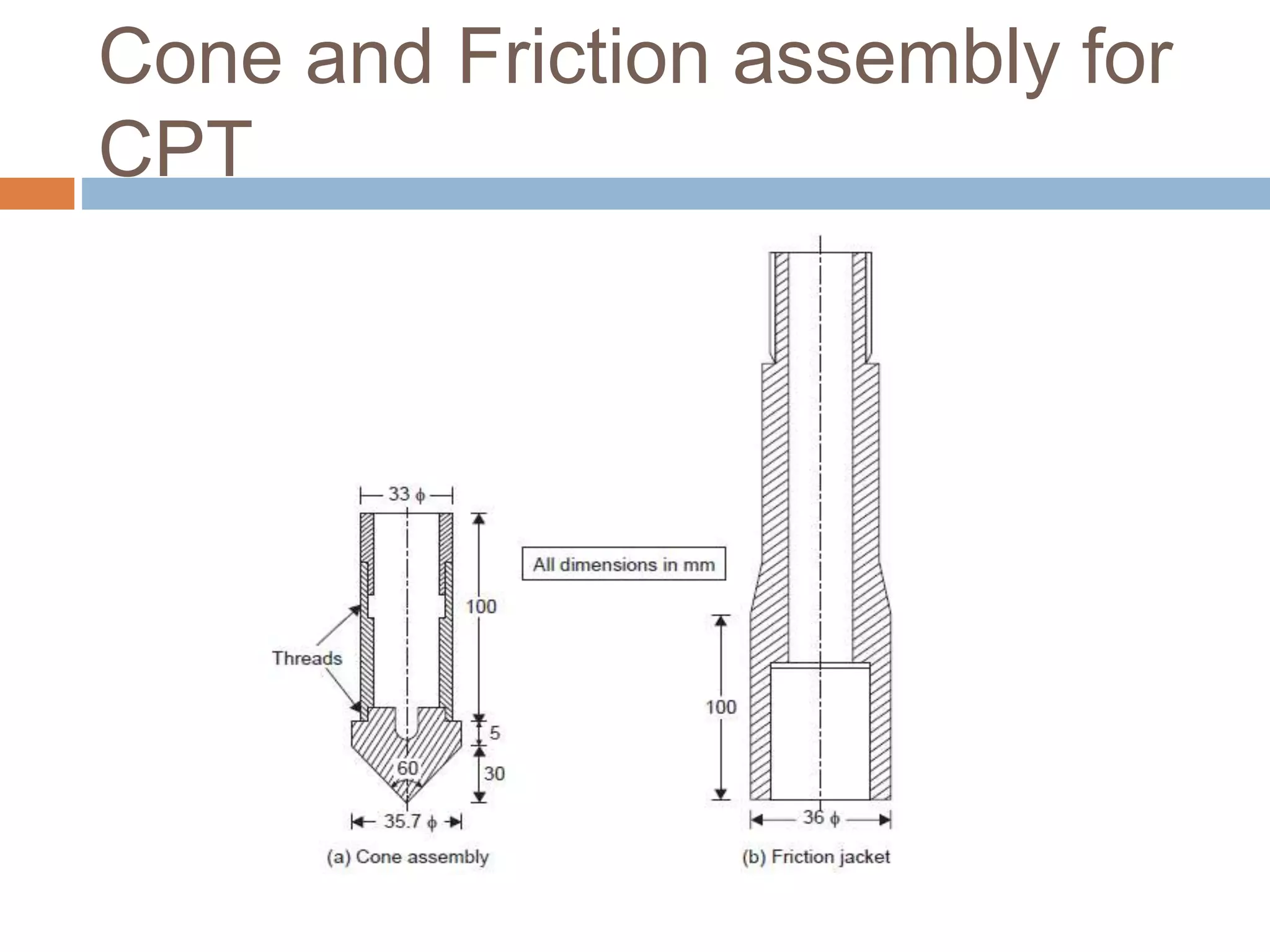
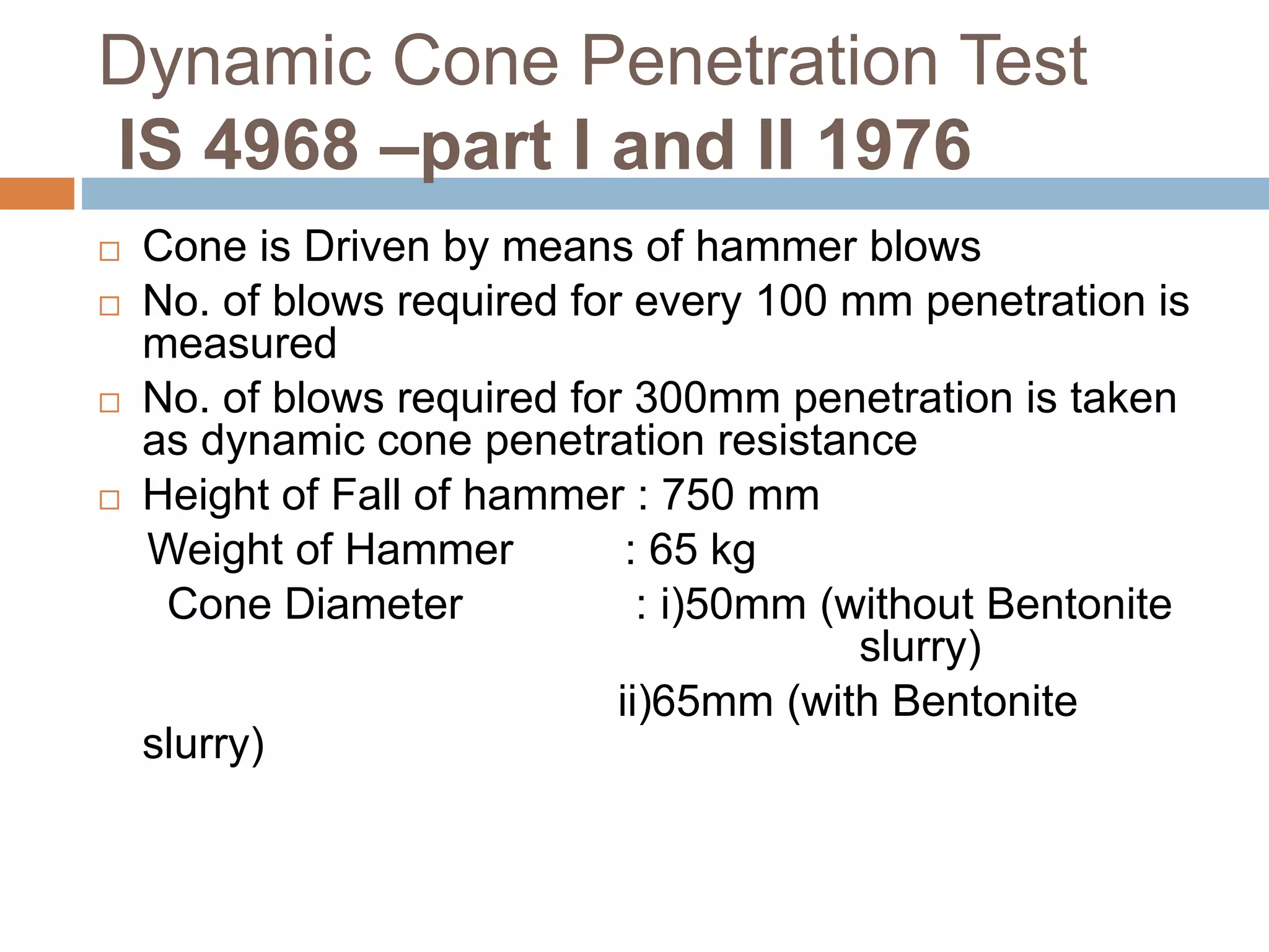
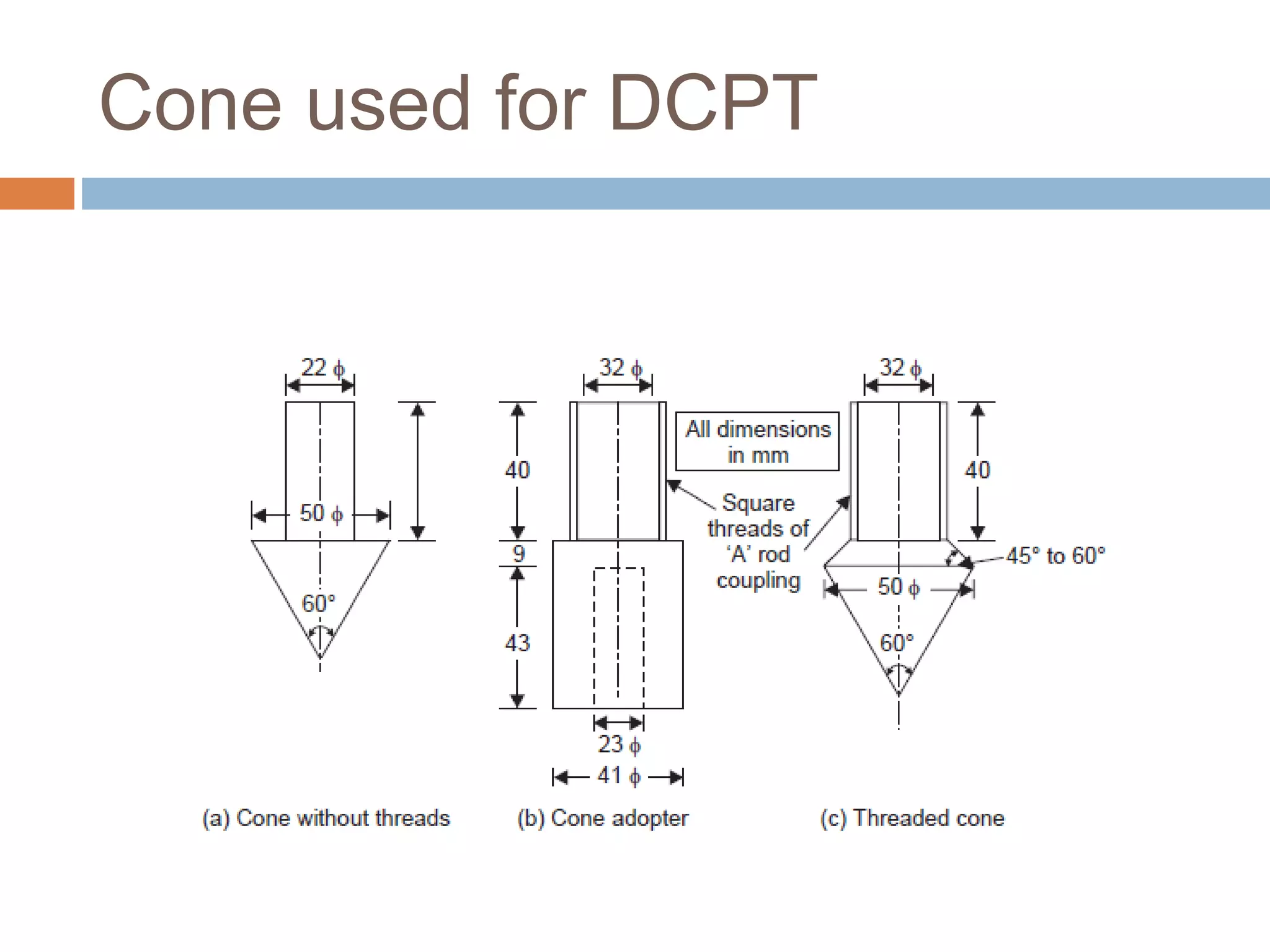
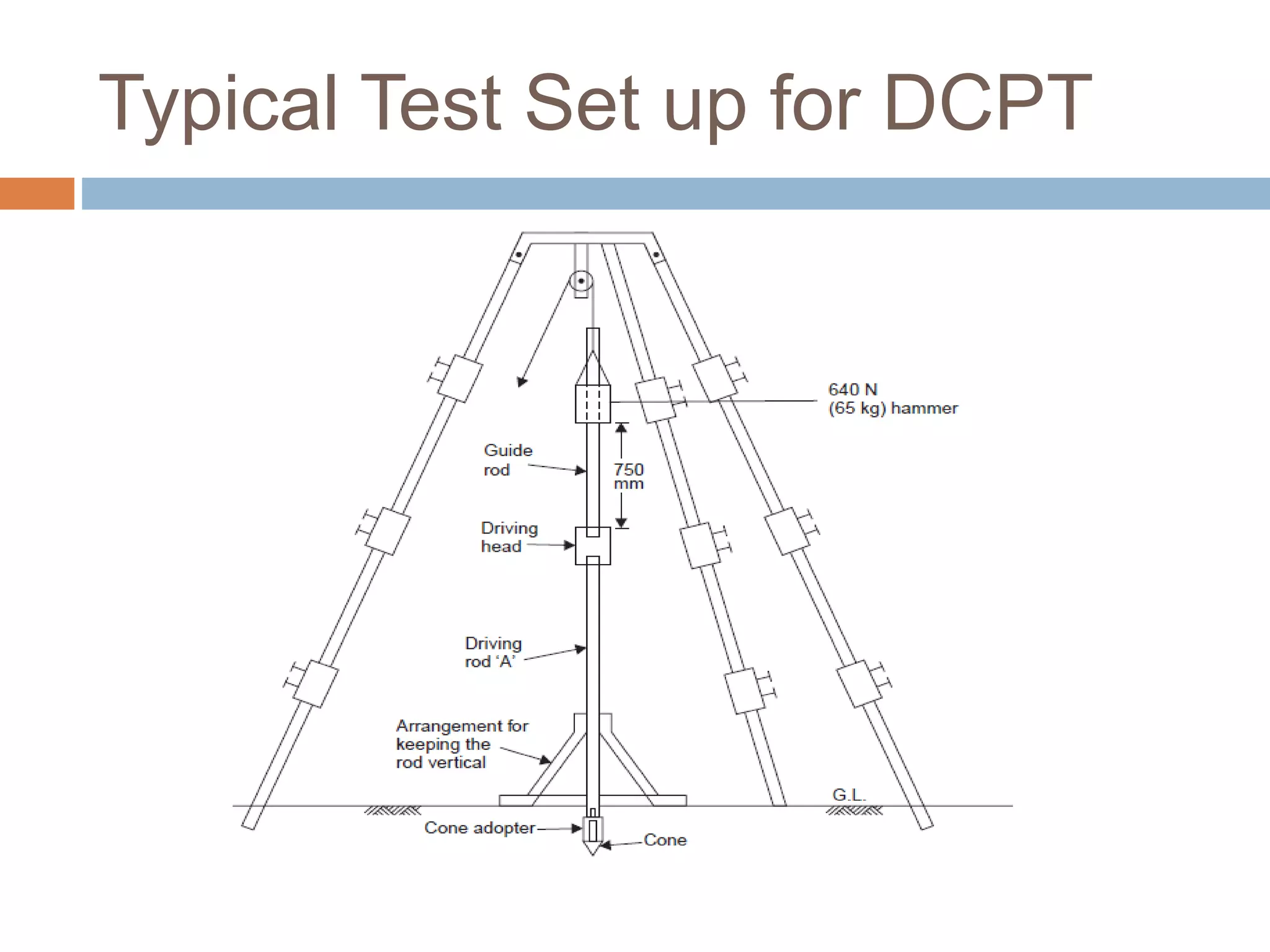
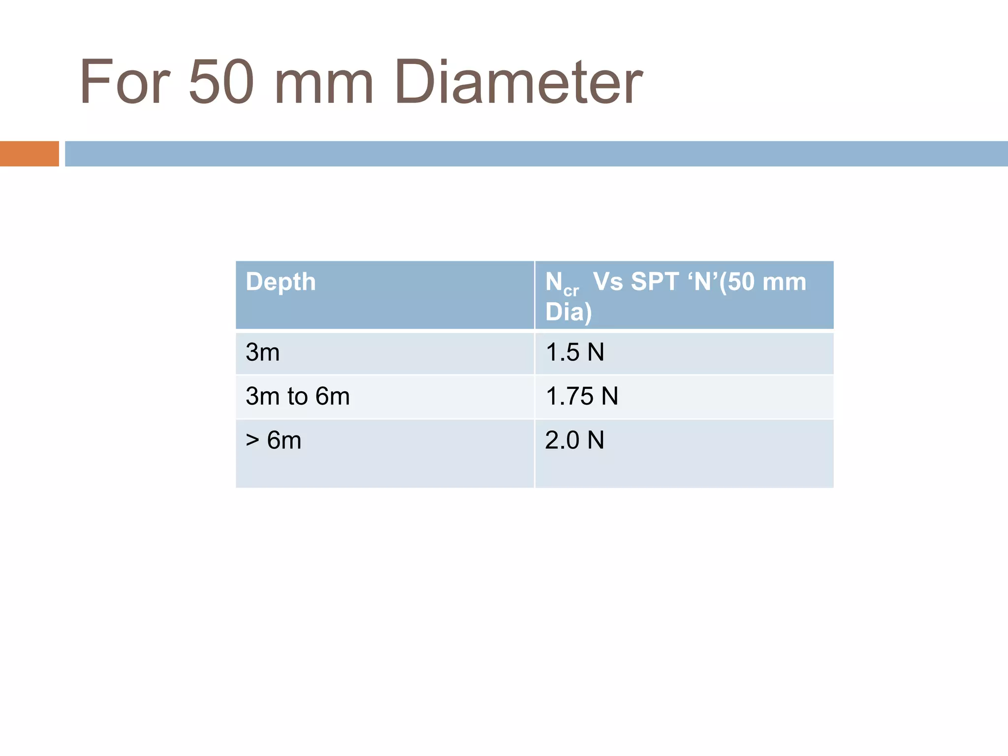
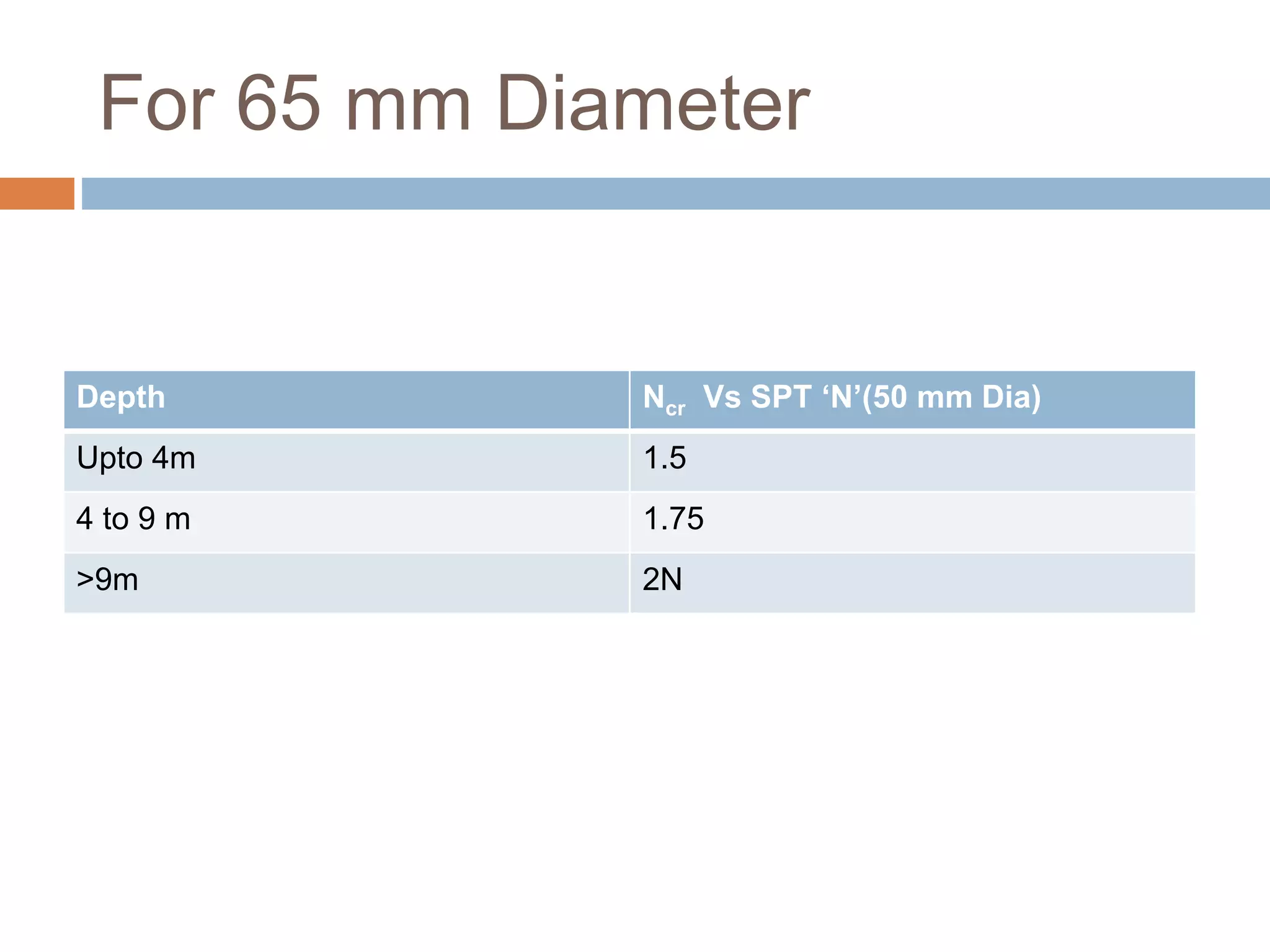
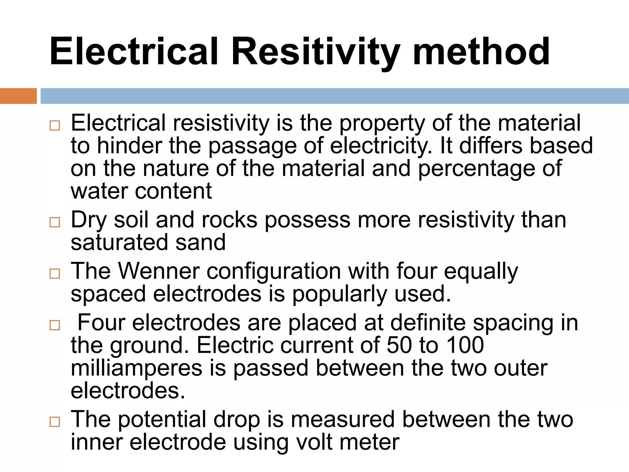
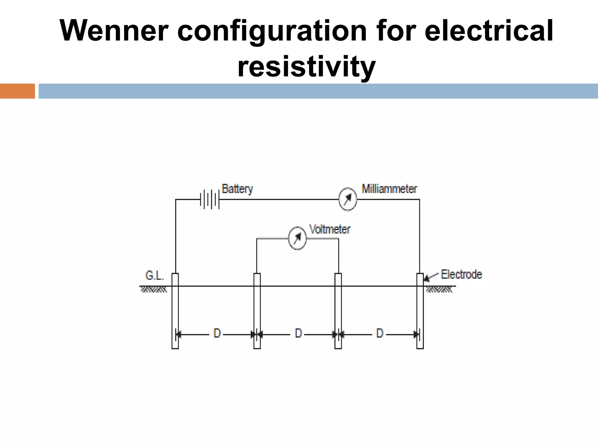
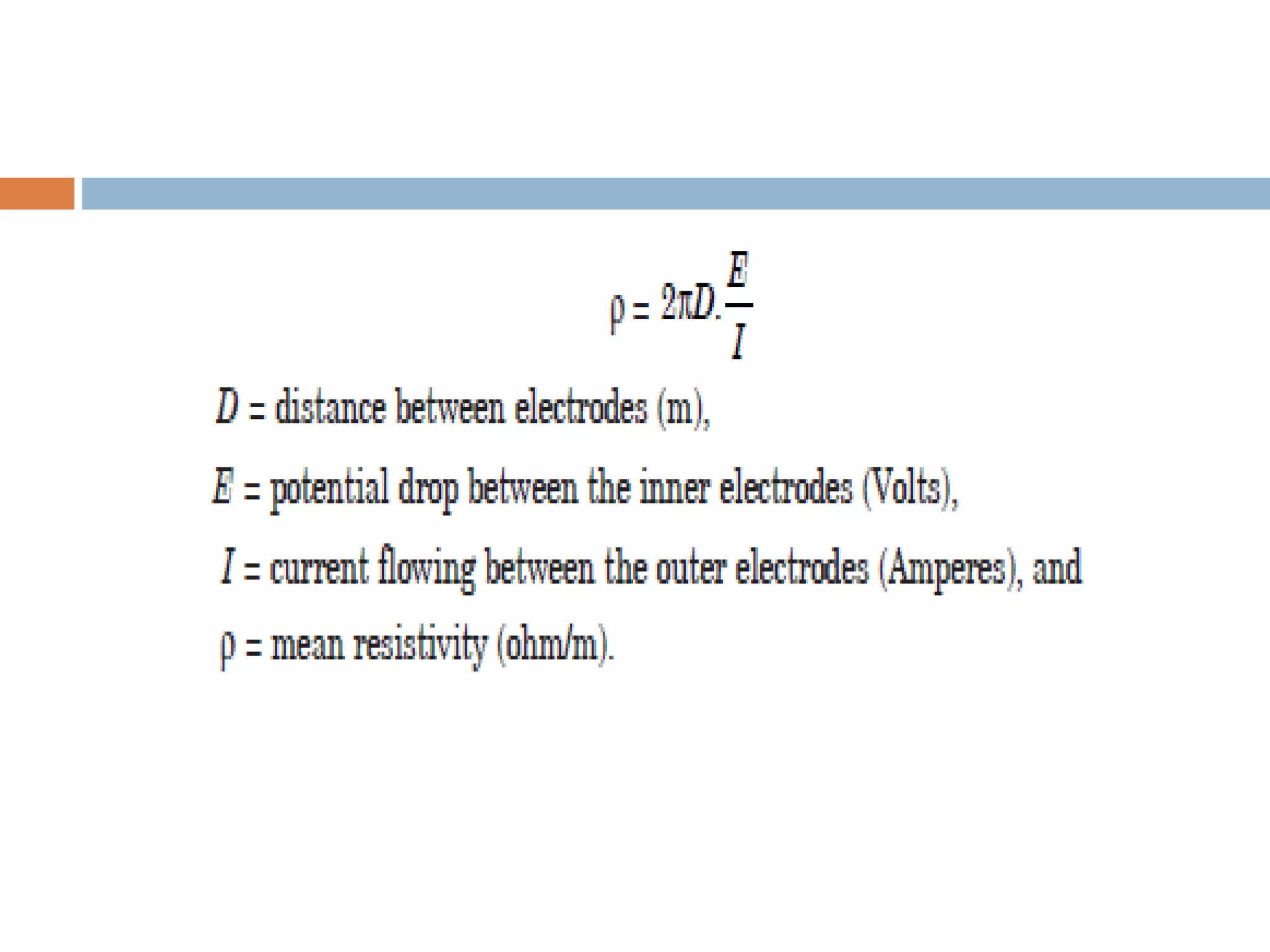
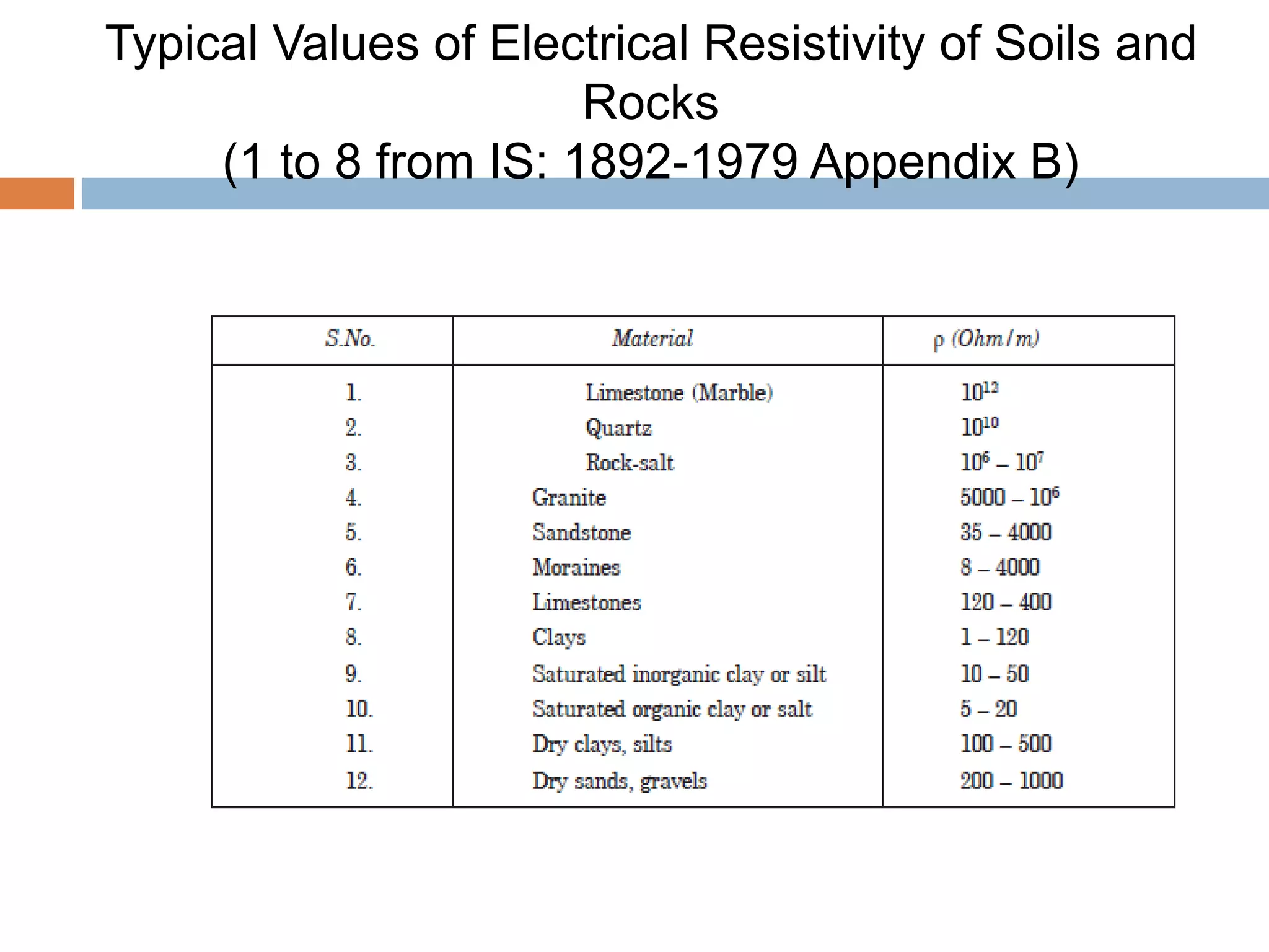
Sounding methods
 Standard penetration Test
 Static Cone Penetration Test
 Dynamic Cone Penetration Test
 This method is also used to skin friction values
which is used to determine the length of the
piles
 The cone is pushed only by thrust and not by
driving
 In order to find out the cone resistance , the
cone alone is pushed
 Later the cone and sleeve is pushed together
to find out the combined frictional and point
resistance of the cone.
 Hydraulic gauges are used for measuring
pressure developed
 Frictional resistance = Combined resistance –
Cone resistance
 Modified Cone penetrometer is known as
Refined Dutch Cone
 Cone penetration resistance is denoted as qc
in kN/m2
 Unlike SPT, this method is also suitable for
clayey deposits
 Unsuitable for gravels and dense sand. For
such soil dynamic Cone penetration is used
Point cone resistance Vs SPT
Correlation
Type of Soil Qc (kN/m2) Vs
SPT ‘N’
Gravel 800 to 1000
Sands 500 to 600
Silty sands 300 to 400
Silts and clayey silts 200
Cone and Friction assembly for
CPT
Dynamic Cone Penetration Test
IS 4968 –part I and II 1976
 Cone is Driven by means of hammer blows
 No. of blows required for every 100 mm penetration is
measured
 No. of blows required for 300mm penetration is taken
as dynamic cone penetration resistance
 Height of Fall of hammer : 750 mm
Weight of Hammer : 65 kg
Cone Diameter : i)50mm (without Bentonite
slurry)
ii)65mm (with Bentonite
slurry)
Cone used for DCPT
Typical Test Set up for DCPT
For 50 mm Diameter
Depth Ncr Vs SPT ‘N’(50 mm
Dia)
3m 1.5 N
3m to 6m 1.75 N
> 6m 2.0 N
For 65 mm Diameter
Depth Ncr Vs SPT ‘N’(50 mm Dia)
Upto 4m 1.5
4 to 9 m 1.75
>9m 2N
Geophysical methods
Geophysical methods are used for
preliminary investigations, are quick and
results are obtained rapidly.
 Seismic Refraction
 Electrical Resitivity
Seismic refraction method
 Shock waves are created either using sledge
hammer or using small explosives
 These shock waves travel through the ground and
are picked up by the detector called geophones
 Geo phones are the devices that detects
vibrations and converts them into measurable
electric signals.
 The travel time of elastic waves are automatically
recorded by seismograph
 The waves which travel along the ground surface
are called primary waves or direct waves. These
arefirst recorded at the geophones
 The waves which travel to the inner surface will
get refracted if the inner layers are denser. These
waves are called refracted waves
 As the distance between the source and the
geophones increases and if the inner layers are
denser, the waves are refracted fast and they
reach the geophones earlier
 The distance at which both the direct and
refracted waves reach the geophones
simultaneously is known as critical distance which
depends on depth and velocity ratio
Seismic refraction method
Typical Wave Velocities for
Different Materials (IS: 1892-1979
Appendix B)
 A graph is plotted between distance and the time. The
reciprocal of slope of the curve gives velocity
 There is a break in the graph which shows critical
distance after which the graph becomes flatter
 The thickness H1 of the top layer is given by, if V1 and
V2 are the velocities of upper and lower layer and dc is
the critical distance.
Distance Vs Time Graph
Limitations
 This method can not be used in the case
where hard layer overlies a soft layer
 This cannot be applicable for concrete or
asphalt pavements, irregular surfaces, surface
with discontinunities like faults, joints etc and
for frozen surfaces
Electrical Resitivity method
 Electrical resistivity is the property of the material
to hinder the passage of electricity. It differs based
on the nature of the material and percentage of
water content
 Dry soil and rocks possess more resistivity than
saturated sand
 The Wenner configuration with four equally
spaced electrodes is popularly used.
 Four electrodes are placed at definite spacing in
the ground. Electric current of 50 to 100
milliamperes is passed between the two outer
electrodes.
 The potential drop is measured between the two
inner electrode using volt meter
Wenner configuration for electrical
resistivity
Typical Values of Electrical Resistivity of Soils and
Rocks
(1 to 8 from IS: 1892-1979 Appendix B)
 Electrical profiling and Electrical sounding are
the two types of field procedure
 Electrical profiling are used for establishing
boundaries between different types of
materials
 Electrical sounding are used to find variation
of soil strata with depth
 The potential drop at each electrode is plotted
against spacing. A change in the curve
indicates the change of strata
Electrode arrangement for electrical
profiling and electrical sounding
Applications
 This method is used to find the depth of water
table. This has practical application in
prospecting for sand and gravel deposits or
ore deposits.
 This is useful in soil investigation for major civil
Engineering construction.
2)indirect methods

2)indirect methods

  • 2.
    Sounding methods  Standardpenetration Test  Static Cone Penetration Test  Dynamic Cone Penetration Test
  • 3.
     This methodis also used to skin friction values which is used to determine the length of the piles  The cone is pushed only by thrust and not by driving  In order to find out the cone resistance , the cone alone is pushed  Later the cone and sleeve is pushed together to find out the combined frictional and point resistance of the cone.  Hydraulic gauges are used for measuring pressure developed
  • 4.
     Frictional resistance= Combined resistance – Cone resistance  Modified Cone penetrometer is known as Refined Dutch Cone  Cone penetration resistance is denoted as qc in kN/m2  Unlike SPT, this method is also suitable for clayey deposits  Unsuitable for gravels and dense sand. For such soil dynamic Cone penetration is used
  • 5.
    Point cone resistanceVs SPT Correlation Type of Soil Qc (kN/m2) Vs SPT ‘N’ Gravel 800 to 1000 Sands 500 to 600 Silty sands 300 to 400 Silts and clayey silts 200
  • 6.
    Cone and Frictionassembly for CPT
  • 7.
    Dynamic Cone PenetrationTest IS 4968 –part I and II 1976  Cone is Driven by means of hammer blows  No. of blows required for every 100 mm penetration is measured  No. of blows required for 300mm penetration is taken as dynamic cone penetration resistance  Height of Fall of hammer : 750 mm Weight of Hammer : 65 kg Cone Diameter : i)50mm (without Bentonite slurry) ii)65mm (with Bentonite slurry)
  • 8.
  • 9.
    Typical Test Setup for DCPT
  • 10.
    For 50 mmDiameter Depth Ncr Vs SPT ‘N’(50 mm Dia) 3m 1.5 N 3m to 6m 1.75 N > 6m 2.0 N
  • 11.
    For 65 mmDiameter Depth Ncr Vs SPT ‘N’(50 mm Dia) Upto 4m 1.5 4 to 9 m 1.75 >9m 2N
  • 12.
    Geophysical methods Geophysical methodsare used for preliminary investigations, are quick and results are obtained rapidly.  Seismic Refraction  Electrical Resitivity
  • 13.
    Seismic refraction method Shock waves are created either using sledge hammer or using small explosives  These shock waves travel through the ground and are picked up by the detector called geophones  Geo phones are the devices that detects vibrations and converts them into measurable electric signals.  The travel time of elastic waves are automatically recorded by seismograph  The waves which travel along the ground surface are called primary waves or direct waves. These arefirst recorded at the geophones
  • 14.
     The waveswhich travel to the inner surface will get refracted if the inner layers are denser. These waves are called refracted waves  As the distance between the source and the geophones increases and if the inner layers are denser, the waves are refracted fast and they reach the geophones earlier  The distance at which both the direct and refracted waves reach the geophones simultaneously is known as critical distance which depends on depth and velocity ratio
  • 16.
  • 17.
    Typical Wave Velocitiesfor Different Materials (IS: 1892-1979 Appendix B)
  • 18.
     A graphis plotted between distance and the time. The reciprocal of slope of the curve gives velocity  There is a break in the graph which shows critical distance after which the graph becomes flatter  The thickness H1 of the top layer is given by, if V1 and V2 are the velocities of upper and lower layer and dc is the critical distance.
  • 19.
  • 20.
    Limitations  This methodcan not be used in the case where hard layer overlies a soft layer  This cannot be applicable for concrete or asphalt pavements, irregular surfaces, surface with discontinunities like faults, joints etc and for frozen surfaces
  • 21.
    Electrical Resitivity method Electrical resistivity is the property of the material to hinder the passage of electricity. It differs based on the nature of the material and percentage of water content  Dry soil and rocks possess more resistivity than saturated sand  The Wenner configuration with four equally spaced electrodes is popularly used.  Four electrodes are placed at definite spacing in the ground. Electric current of 50 to 100 milliamperes is passed between the two outer electrodes.  The potential drop is measured between the two inner electrode using volt meter
  • 22.
    Wenner configuration forelectrical resistivity
  • 24.
    Typical Values ofElectrical Resistivity of Soils and Rocks (1 to 8 from IS: 1892-1979 Appendix B)
  • 25.
     Electrical profilingand Electrical sounding are the two types of field procedure  Electrical profiling are used for establishing boundaries between different types of materials  Electrical sounding are used to find variation of soil strata with depth  The potential drop at each electrode is plotted against spacing. A change in the curve indicates the change of strata
  • 26.
    Electrode arrangement forelectrical profiling and electrical sounding
  • 27.
    Applications  This methodis used to find the depth of water table. This has practical application in prospecting for sand and gravel deposits or ore deposits.  This is useful in soil investigation for major civil Engineering construction.