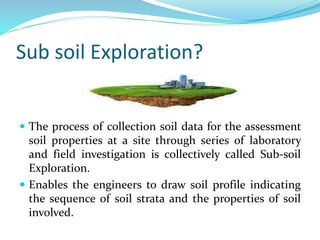
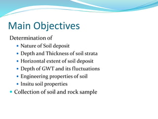
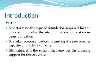
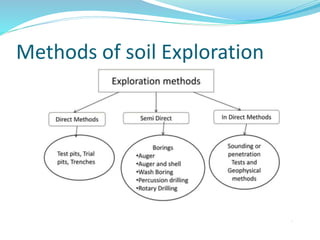
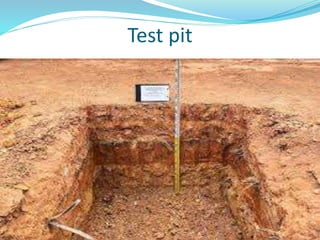
Sub soil Exploration?
 The process of collection soil data for the assessment
soil properties at a site through series of laboratory
and field investigation is collectively called Sub-soil
Exploration.
 Enables the engineers to draw soil profile indicating
the sequence of soil strata and the properties of soil
involved.
Main Objectives
Determination of
 Nature of Soil deposit
 Depth and Thickness of soil strata
 Horizontal extent of soil deposit
 Depth of GWT and its fluctuations
 Engineering properties of soil
 Insitu soil properties
 Collection of soil and rock sample
Introduction
WHAT?
 Attempt at understanding the subsurface conditions such
as:
 Soil and rock profile
 Geological features of the region
 Position and variation of ground water table
 Physical properties of soil and rock
 Contamination, if any
 General data of adjacent structures,
 hydrological data, topography, soil maps, seismicity, etc.
 Engineering properties of soil
Introduction
WHY?
 To determine the type of foundation required for the
proposed project at the site, i.e. shallow foundation or
deep foundation.
 To make recommendations regarding the safe bearing
capacity or pile load capacity.
 Ultimately, it is the subsoil that provides the ultimate
support for the structures.
Introduction
HOW?
 The three important aspect are planning, execution
and report writing.
 Planning
 To minimize cost of explorations and yet give reliable
data.
 Decide on quantity and quality depending on type,
size and importance of project and whether
investigation is preliminary or detailed.
Introduction
 Execution:
 Collection of disturbed and/or undisturbed samples of
subsurface strata from field.
 Conducting in-situ tests of subsurface material and
obtaining properties directly or indirectly.
 Study of ground water conditions and collection of
sample for chemical analysis.
 Geophysical exploration, if necessary.
 Laboratory testing on samples.
Introduction
 Report writing:
 Description of site conditions – topographic features,
hydraulic conditions, existing structures, etc.
supplemented by plans/drawings.
 Description of nature, type and importance of proposed
construction
 Description of field and lab tests carried out.
 Analysis and discussion of data collected
 Preparation of charts, tables, graphs, etc.
 Calculations performed
 Recommendations
Introduction
A complete site investigation will consist of:
 Preliminary work
 Collecting general information and already existing
data such as study of geologic , seismic maps, etc. at or
near site.
 Study site history – if previously used as quarry,
agricultural land, industrial unit, etc.
 Site Reconnaissance: Actual site inspection.
 To judge general suitability
 Decide exploration techniques
Introduction
 Exploration
 Preliminary Investigations: Exploratory borings or shallow
test pits, representative sampling, geophysical
investigations, etc
 Detailed Investigations: Deep boreholes, extensive
sampling, in-situ testing, lab testing, etc.
 Depth and spacing: In general, depth of investigation
should be such that any/all strata that are likely to
experience settlement or failure due to loading. Spacing
depends upon degree of variation of surface topography
and subsurface strata in horizontal direction. Refer to Alam
Singh.
Methods of soil Exploration
Test pits
 Depth up to 3m
 Uneconomical at greater depths.
 Supports are required at greater depths. Especially in
case of weak strata
 Problems with GWT and the same should be lowered
 Open type Exploration
 Soils are investigated in natural condition
 Soil samples are collected for determining strength
and Engineering properties
Test pit
Boring
Drilling a hole into the soil strata up to specified depth is
known as boring
 1. Auger boring
 2. Auger and shell boring
 3. Wash boring
 4. Percussion drilling
 5. Rotary drilling
Auger Boring
 Drilling is made using a device called Soil Auger
 Power driven (up to 3 to 5m) and Hand operated
(Greater than 5m).
 Advancement is made by drilling the auger by
simultaneous rotating and pressing it into the soil
 Dry and unsupported bore holes
 When the auger gets filled with soil same, it is taken
out and the soil sample collected.
Soil Augers
Auger and Shell Boring
 Casing is provided in case of weak strata
 First the casing is driven and then the auger
 Boring rig is used for power driving (hand rig for depth
up to 25 m)
 Soft rocks are broken using chisel bits
 Sand pumps are used in the case of sandy soils.
Disadvantage:
 Whenever the casing is to be extended, the auger has
to be withdrawn which hinders the quick progress of
the work.
Wash Boring
 Below GWT, May not be used for soils mixed with gravel and
boulders
 Initially, the hole is advanced for a short depth by using an auger.
 Then a casing pipe is pushed in and driven with a drop weight.
The driving may be with the aid of power.
 A hollow drill bit is screwed to a hollow drill rod connected to a
rope passing over a pulley and supported by a tripod.
 Water jet under pressure is forced through the rod and the bit
into the hole.
 This loosens the soil at the lower end and forces the soil- water
suspension upwards along the annular surface between the rod
and the side of the hole
 This suspension is collected in a settling tank.
 Soil particles are allowed to settle down and water is
allowed to overflow into a sump which is then
recirculated.
 Very disturbed sample is obtained. Hence cannot be
used for determining engineering properties.
 whenever a soil sample is required, the chopping bit is
to be replaced by a sampler.
 The change of the rate of progress and change of
colour of wash water indicate changes in soil strata.
Wash Boring
Percussion Drilling
 Percussion drilling is a drilling method which involves
lifting and dropping heavy tools to break rock, and uses
steel casing tubes to stop the borehole from collapsing.
 Water is added to facilitate the breaking of stiff soil or rock.
 The slurry of the pulverized material is bailed out at
intervals.
Disadvantages
 Cannot be used in loose sand and is slow in plastic clay.
 The formation gets badly disturbed by impact.
Percussion Drilling
Rotary Drilling
 Suitable for rock formations.
 A drill bit, fixed to the lower end of a drill rod, is rotated by
power while being kept in firm contact with the hole.
 Drilling fluid or bentonite slurry is used under pressure
which brings up the cuttings to the surface.
 Even rock cores may be obtained by using suitable
diamond drill bits.
Disadvantages
 Not used in porous deposits as the consumption of drilling
fluid would be high.
Rotary Drilling
Indirect methods
There is two types of indirect methods:
 Sounding or penetration Tests
 Geophysical methods
SPT “IS: 2131-1986— Standard
Penetration Test”.
 Generally used for cohesion less soils
 To determine relative density , angle of shearing
resistance, UCS.
 A bore hole is made using drilling tools and a hammer
of weight 63.5 falling from the height of 750 mm at the
rate of 30 blows/minute
 After reaching the specified depth, the drilling tool is
replaced by a split spoon sampler to collect soil
sample.
 First 150 mm penetration is taken as seating drive and
the no. of blows required for that penetration is
discarded
 No of blows required for next 300mm penetration after
seating drive is taken as standard penetration number
(N)
 No of blows greater than 50 are taken as refusal and
the test is discontinued
 Corrections are applied to the observed N value
Standard Penetration Test
Static Cone Penetration Test(SCPT)
 This method is used to determine penetration
resistance of soil
 Also known as Dutch cone Test
 Cone Dimensions
Apex Angle: 60°
Overall Diameter: 35.7 mm
End Area : 10 cm²
 Rate of penetration: 10 mm/s
 Depth of penetration: 35 mm/s
Static Cone Penetration Test(SCPT)
 This method is also used to skin friction values which
is used to determine the length of the piles
 The cone is pushed only by thrust and not by driving
 In order to find out the cone resistance , the cone alone
is pushed
 Later the cone and sleeve is pushed together to find
out the combined frictional and point resistance of the
cone.
 Hydraulic gauges are used for measuring pressure
developed
 Frictional resistance = Combined resistance – Cone
resistance
 Modified Cone penetrometer is known as Refined
Dutch Cone
 Cone penetration resistance is denoted as qc in kN/m2
 Unlike SPT, this method is also suitable for clayey
deposits
 Unsuitable for gravels and dense sand. For such soil
dynamic Cone penetration is used
SCPT
Geophysical methods
 The stratification of soils and rocks can be determined by
geophysical methods of exploration which measures changes in
certain physical characteristics of these materials, for example
density, magnetism, electrical resistivity, etc.
The following two geophysical methods are commonly used:
(i)Seismic refraction method
(ii)Electrical resistivity method
(i)Seismic Refraction Method:
 The seismic refraction method is based on the principal that
seismic waves have different velocities in different types of soil. The
seismic refraction method is more suited to shallow exploration for
civil engineering purposes. Geophysical methods:
(ii)Electrical resistivity method
 The electrical resistivity d is given by
 ℓ=2*3.14*D*V/I
 ℓ=mean resistivity (ohm/m)
 D=distance between electrodes (m)
 V =potential drop between two inner electrodes (volts)
 I=current applied between two outer electrodes (Amperes)
Limitations:
 (i)The methods are capable of detecting only the strata
having different electrical resistivity.
 (ii)The services of an expert in the field are needed.
SUBSOIL EXPLORATION 35.pptx

SUBSOIL EXPLORATION 35.pptx

  • 2.
    Sub soil Exploration? The process of collection soil data for the assessment soil properties at a site through series of laboratory and field investigation is collectively called Sub-soil Exploration.  Enables the engineers to draw soil profile indicating the sequence of soil strata and the properties of soil involved.
  • 3.
    Main Objectives Determination of Nature of Soil deposit  Depth and Thickness of soil strata  Horizontal extent of soil deposit  Depth of GWT and its fluctuations  Engineering properties of soil  Insitu soil properties  Collection of soil and rock sample
  • 4.
    Introduction WHAT?  Attempt atunderstanding the subsurface conditions such as:  Soil and rock profile  Geological features of the region  Position and variation of ground water table  Physical properties of soil and rock  Contamination, if any  General data of adjacent structures,  hydrological data, topography, soil maps, seismicity, etc.  Engineering properties of soil
  • 5.
    Introduction WHY?  To determinethe type of foundation required for the proposed project at the site, i.e. shallow foundation or deep foundation.  To make recommendations regarding the safe bearing capacity or pile load capacity.  Ultimately, it is the subsoil that provides the ultimate support for the structures.
  • 6.
    Introduction HOW?  The threeimportant aspect are planning, execution and report writing.  Planning  To minimize cost of explorations and yet give reliable data.  Decide on quantity and quality depending on type, size and importance of project and whether investigation is preliminary or detailed.
  • 7.
    Introduction  Execution:  Collectionof disturbed and/or undisturbed samples of subsurface strata from field.  Conducting in-situ tests of subsurface material and obtaining properties directly or indirectly.  Study of ground water conditions and collection of sample for chemical analysis.  Geophysical exploration, if necessary.  Laboratory testing on samples.
  • 8.
    Introduction  Report writing: Description of site conditions – topographic features, hydraulic conditions, existing structures, etc. supplemented by plans/drawings.  Description of nature, type and importance of proposed construction  Description of field and lab tests carried out.  Analysis and discussion of data collected  Preparation of charts, tables, graphs, etc.  Calculations performed  Recommendations
  • 9.
    Introduction A complete siteinvestigation will consist of:  Preliminary work  Collecting general information and already existing data such as study of geologic , seismic maps, etc. at or near site.  Study site history – if previously used as quarry, agricultural land, industrial unit, etc.  Site Reconnaissance: Actual site inspection.  To judge general suitability  Decide exploration techniques
  • 10.
    Introduction  Exploration  PreliminaryInvestigations: Exploratory borings or shallow test pits, representative sampling, geophysical investigations, etc  Detailed Investigations: Deep boreholes, extensive sampling, in-situ testing, lab testing, etc.  Depth and spacing: In general, depth of investigation should be such that any/all strata that are likely to experience settlement or failure due to loading. Spacing depends upon degree of variation of surface topography and subsurface strata in horizontal direction. Refer to Alam Singh.
  • 11.
    Methods of soilExploration
  • 12.
    Test pits  Depthup to 3m  Uneconomical at greater depths.  Supports are required at greater depths. Especially in case of weak strata  Problems with GWT and the same should be lowered  Open type Exploration  Soils are investigated in natural condition  Soil samples are collected for determining strength and Engineering properties
  • 13.
  • 14.
    Boring Drilling a holeinto the soil strata up to specified depth is known as boring  1. Auger boring  2. Auger and shell boring  3. Wash boring  4. Percussion drilling  5. Rotary drilling
  • 15.
    Auger Boring  Drillingis made using a device called Soil Auger  Power driven (up to 3 to 5m) and Hand operated (Greater than 5m).  Advancement is made by drilling the auger by simultaneous rotating and pressing it into the soil  Dry and unsupported bore holes  When the auger gets filled with soil same, it is taken out and the soil sample collected.
  • 16.
  • 17.
    Auger and ShellBoring  Casing is provided in case of weak strata  First the casing is driven and then the auger  Boring rig is used for power driving (hand rig for depth up to 25 m)  Soft rocks are broken using chisel bits  Sand pumps are used in the case of sandy soils. Disadvantage:  Whenever the casing is to be extended, the auger has to be withdrawn which hinders the quick progress of the work.
  • 18.
    Wash Boring  BelowGWT, May not be used for soils mixed with gravel and boulders  Initially, the hole is advanced for a short depth by using an auger.  Then a casing pipe is pushed in and driven with a drop weight. The driving may be with the aid of power.  A hollow drill bit is screwed to a hollow drill rod connected to a rope passing over a pulley and supported by a tripod.  Water jet under pressure is forced through the rod and the bit into the hole.  This loosens the soil at the lower end and forces the soil- water suspension upwards along the annular surface between the rod and the side of the hole
  • 19.
     This suspensionis collected in a settling tank.  Soil particles are allowed to settle down and water is allowed to overflow into a sump which is then recirculated.  Very disturbed sample is obtained. Hence cannot be used for determining engineering properties.  whenever a soil sample is required, the chopping bit is to be replaced by a sampler.  The change of the rate of progress and change of colour of wash water indicate changes in soil strata.
  • 20.
  • 21.
    Percussion Drilling  Percussiondrilling is a drilling method which involves lifting and dropping heavy tools to break rock, and uses steel casing tubes to stop the borehole from collapsing.  Water is added to facilitate the breaking of stiff soil or rock.  The slurry of the pulverized material is bailed out at intervals. Disadvantages  Cannot be used in loose sand and is slow in plastic clay.  The formation gets badly disturbed by impact.
  • 22.
  • 23.
    Rotary Drilling  Suitablefor rock formations.  A drill bit, fixed to the lower end of a drill rod, is rotated by power while being kept in firm contact with the hole.  Drilling fluid or bentonite slurry is used under pressure which brings up the cuttings to the surface.  Even rock cores may be obtained by using suitable diamond drill bits. Disadvantages  Not used in porous deposits as the consumption of drilling fluid would be high.
  • 24.
  • 25.
    Indirect methods There istwo types of indirect methods:  Sounding or penetration Tests  Geophysical methods
  • 26.
    SPT “IS: 2131-1986—Standard Penetration Test”.  Generally used for cohesion less soils  To determine relative density , angle of shearing resistance, UCS.  A bore hole is made using drilling tools and a hammer of weight 63.5 falling from the height of 750 mm at the rate of 30 blows/minute  After reaching the specified depth, the drilling tool is replaced by a split spoon sampler to collect soil sample.
  • 27.
     First 150mm penetration is taken as seating drive and the no. of blows required for that penetration is discarded  No of blows required for next 300mm penetration after seating drive is taken as standard penetration number (N)  No of blows greater than 50 are taken as refusal and the test is discontinued  Corrections are applied to the observed N value
  • 28.
  • 29.
    Static Cone PenetrationTest(SCPT)  This method is used to determine penetration resistance of soil  Also known as Dutch cone Test  Cone Dimensions Apex Angle: 60° Overall Diameter: 35.7 mm End Area : 10 cm²  Rate of penetration: 10 mm/s  Depth of penetration: 35 mm/s
  • 30.
    Static Cone PenetrationTest(SCPT)  This method is also used to skin friction values which is used to determine the length of the piles  The cone is pushed only by thrust and not by driving  In order to find out the cone resistance , the cone alone is pushed  Later the cone and sleeve is pushed together to find out the combined frictional and point resistance of the cone.  Hydraulic gauges are used for measuring pressure developed
  • 31.
     Frictional resistance= Combined resistance – Cone resistance  Modified Cone penetrometer is known as Refined Dutch Cone  Cone penetration resistance is denoted as qc in kN/m2  Unlike SPT, this method is also suitable for clayey deposits  Unsuitable for gravels and dense sand. For such soil dynamic Cone penetration is used
  • 32.
  • 33.
    Geophysical methods  Thestratification of soils and rocks can be determined by geophysical methods of exploration which measures changes in certain physical characteristics of these materials, for example density, magnetism, electrical resistivity, etc. The following two geophysical methods are commonly used: (i)Seismic refraction method (ii)Electrical resistivity method (i)Seismic Refraction Method:  The seismic refraction method is based on the principal that seismic waves have different velocities in different types of soil. The seismic refraction method is more suited to shallow exploration for civil engineering purposes. Geophysical methods:
  • 34.
    (ii)Electrical resistivity method The electrical resistivity d is given by  ℓ=2*3.14*D*V/I  ℓ=mean resistivity (ohm/m)  D=distance between electrodes (m)  V =potential drop between two inner electrodes (volts)  I=current applied between two outer electrodes (Amperes) Limitations:  (i)The methods are capable of detecting only the strata having different electrical resistivity.  (ii)The services of an expert in the field are needed.