Downloaded 366 times

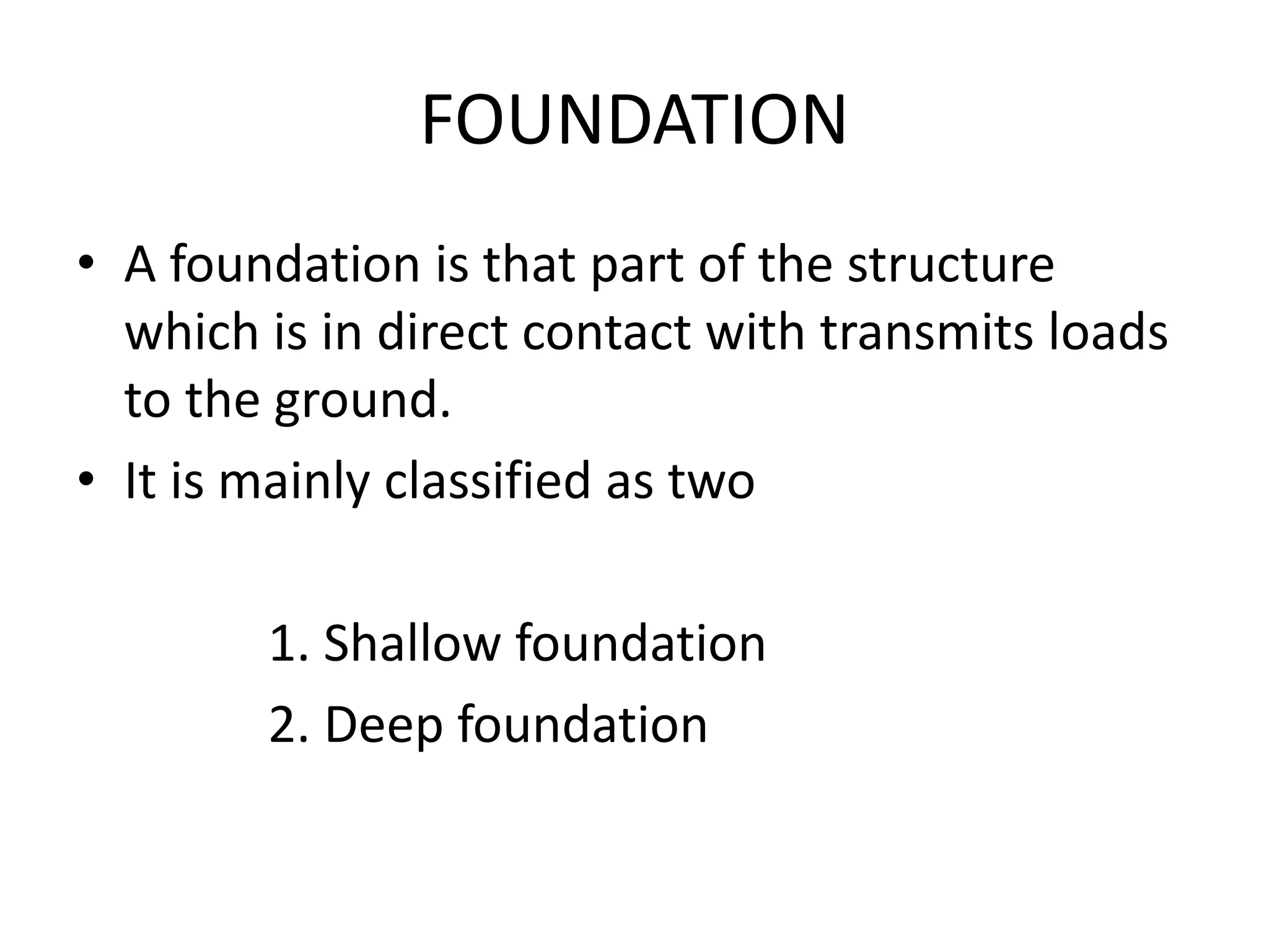
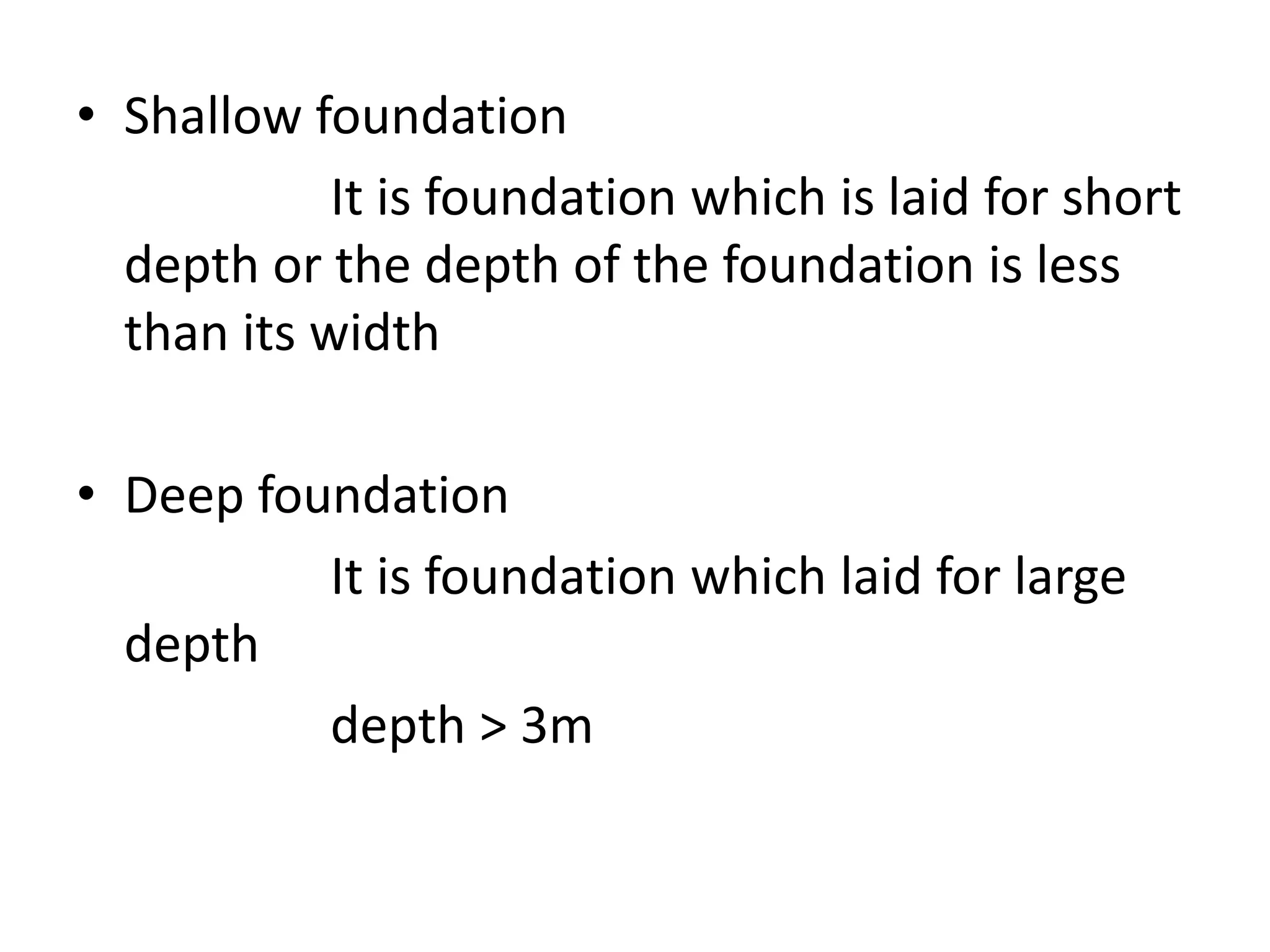
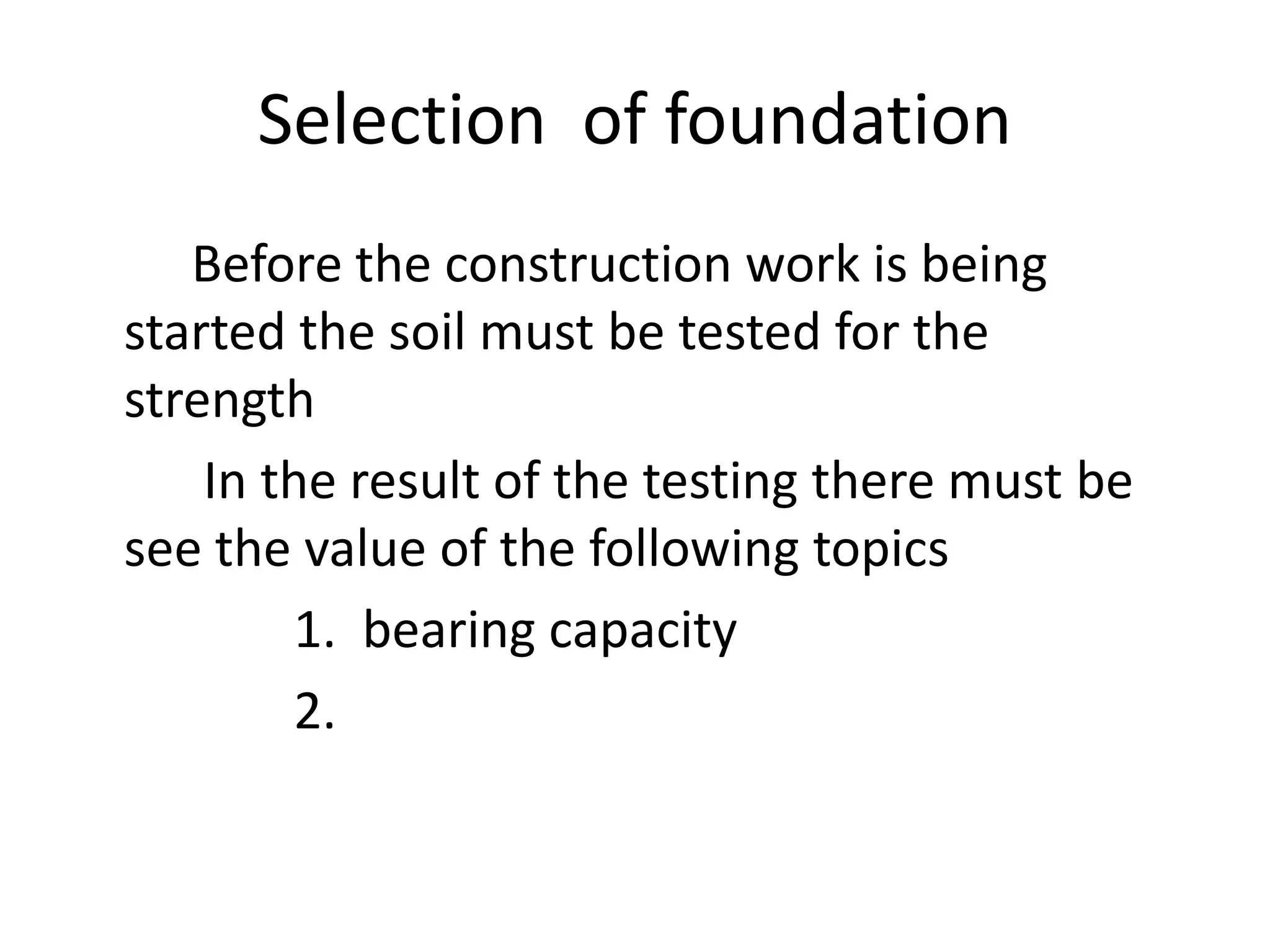
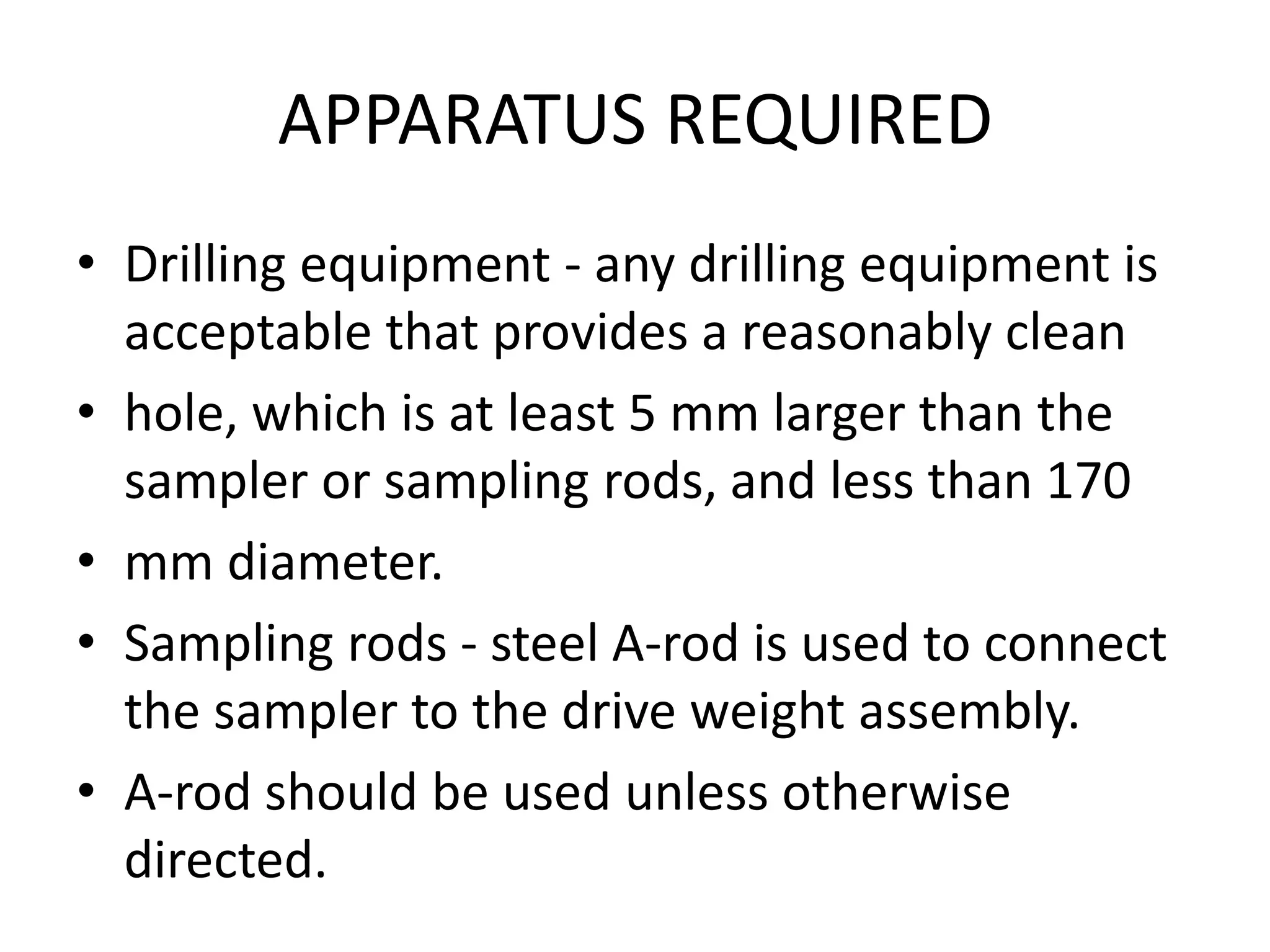
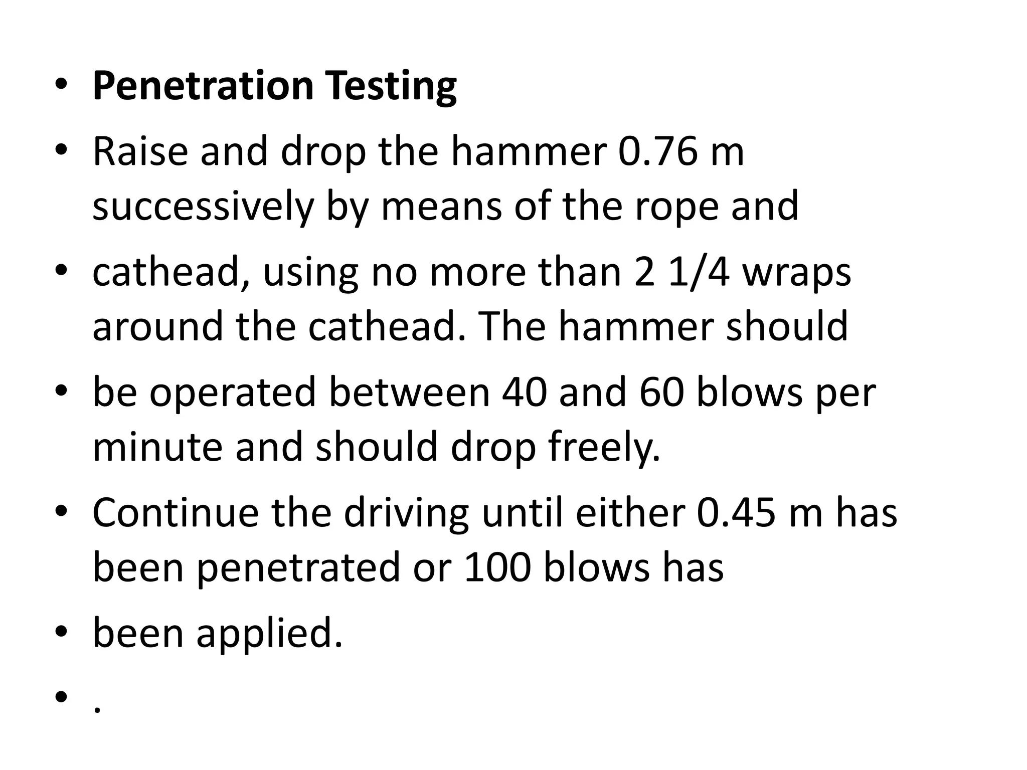
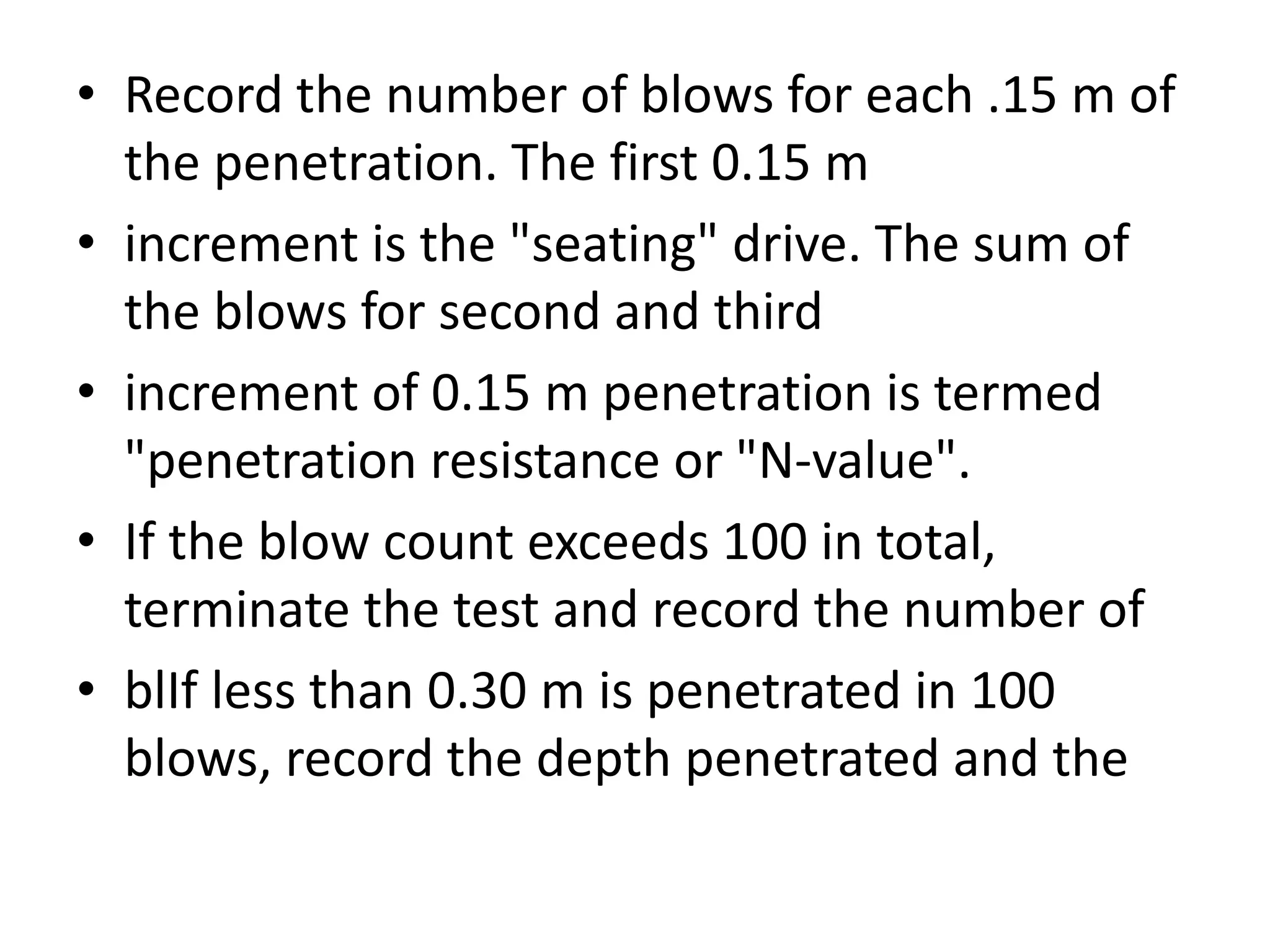
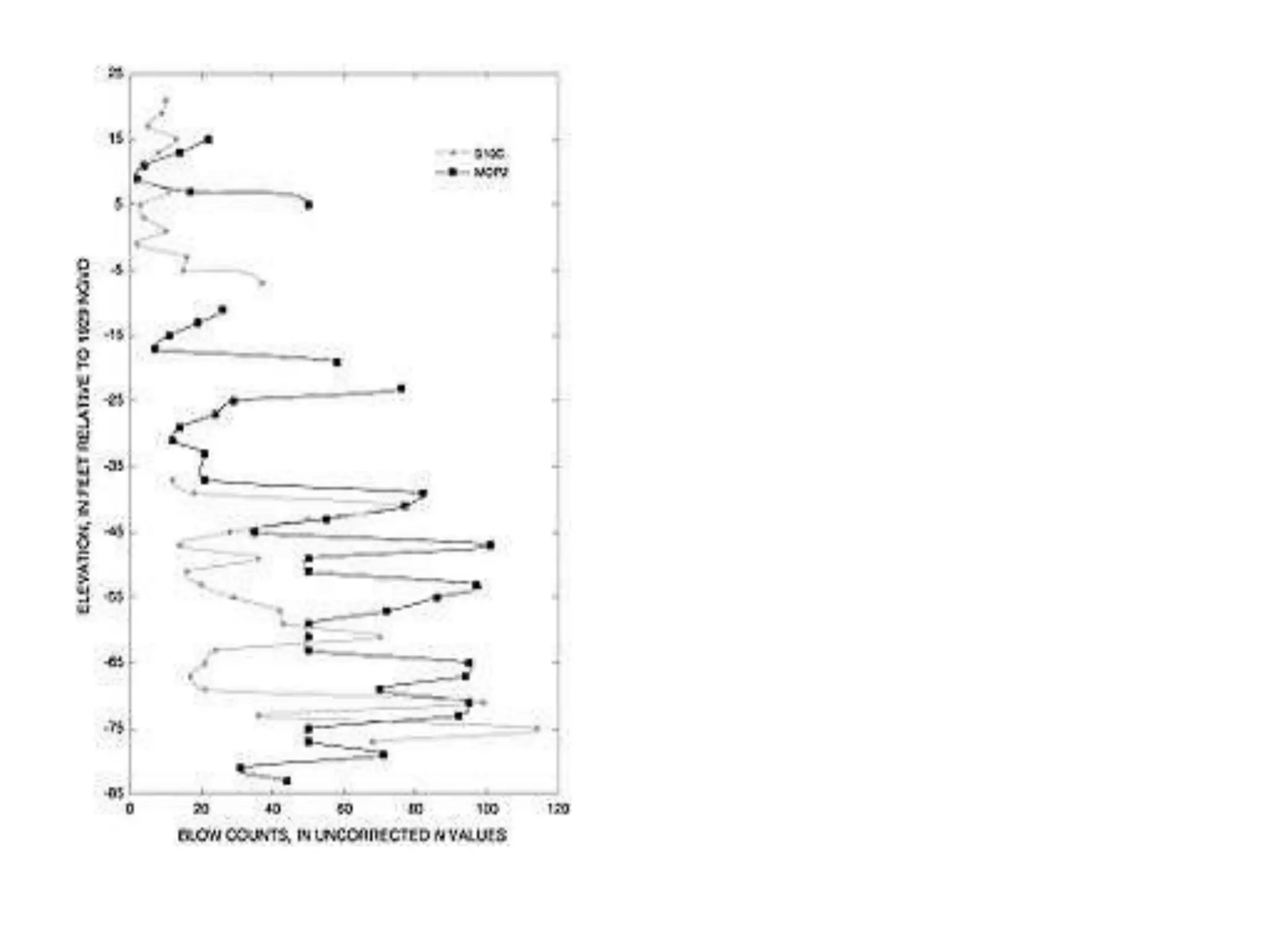
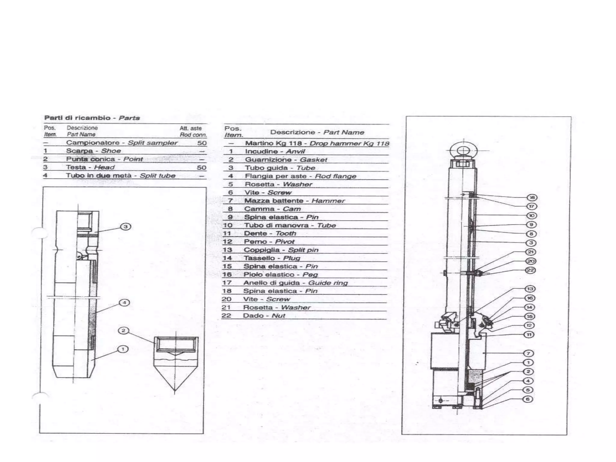

1) Foundations can be either shallow or deep, with shallow foundations having a depth less than their width and deep foundations having a depth greater than 3 meters. 2) Before construction, soil must be tested to determine its bearing capacity and strength. 3) Standard penetration tests involve drilling a hole, lowering a split-barrel sampler attached to rods, and recording the blow count as the sampler is driven into the soil in three successive 0.15 meter increments.


![Geotechnical Engineering-II [Lec #19: General Bearing Capacity Equation]](https://cdn.slidesharecdn.com/ss_thumbnails/19-181123045917-thumbnail.jpg?width=640&height=640&fit=bounds)


