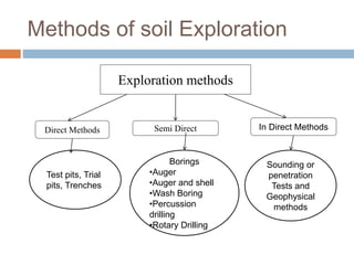
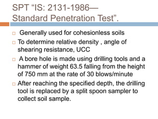
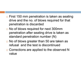
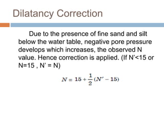
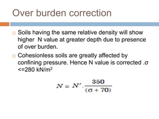
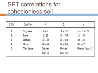
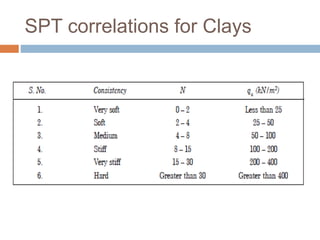
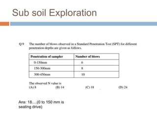
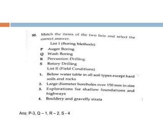
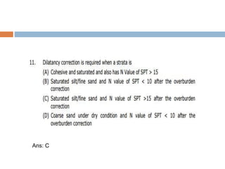
SUBSOIL
EXPLORATION
UNIT 1
Sub soil Exploration???
 The process of collection soil data for the
assessment soil properties at a site through
series of laboratory and field investigation is
collectively called Sub-soil Exploration
 Enables the engineers to draw soil profile
indicating the sequence of soil strata and the
properties of soil involved.
Main Objectives
Determination of
 Nature of Soil deposit
 Depth and Thickness of soil strata
 Horizontal extent of soil deposit
 Depth of GWT and its fluctuations
 Engineering properties of soil
 Insitu soil properties
 Collection of soil and rock sample
Methods of soil Exploration
Exploration methods
Direct Methods Semi Direct In Direct Methods
Test pits, Trial
pits, Trenches
Borings
•Auger
•Auger and shell
•Wash Boring
•Percussion
drilling
•Rotary Drilling
Sounding or
penetration
Tests and
Geophysical
methods
Test pits
 Depth upto 3m
 Uneconomical at greater depths.
 Supports are required at greater depths.
Especially in case of weak strata
 Problems with GWT and the same should be
lowered
 Open type Exploration
 Soils are investigated in natural condition
 Soil samples are collected for determining
strength and Engineering properties
Excavated test pit
Boring
Drilling a hole into the soil strata upto
specified depth is known as boring
1. Auger boring
2. Auger and shell boring
3. Wash boring
4. Percussion drilling
5. Rotary drilling
Auger Boring
 Drilling is made using a device called Soil
Auger
 Power driven (upto 3 to 5m) and Hand
operated (Greater than 5m)
 Advancement is made by drilling the auger by
simultaneous rotating and pressing it into the
soil
 Dry and unsupported bore holes
 When the auger gets filled with soil same, it is
taken out and the soil sample collected
Soil augers
Auger and Shell Boring
 Casing is provided in case of weak strata
 First the casing is driven and then the auger
 Boring rig is used for power drivng (hand rig for
depth upto 25 m)
 Soft rocks are broken using chisel bits
 Sand pumps are used in the case of sandy soils.
Disadvantage:
 Whenever the casing is to be extended, the auger
has to be withdrawn which hinders the quick
progress of the work.
Typical set up for Wash boring
Wash Boring
 Below GWT. May not be used for soils mixed with gravel
and boulders
 Initially, the hole is advanced for a short depth by using
an auger.
 Then a casing pipe is pushed in and driven with a drop
weight. The driving may be with the aid of power.
 A hollow drill bit is screwed to a hollow drill rod
connected to a rope passing over a pulley and
supported by a tripod.
 Water jet under pressure is forced through the rod and
the bit into the hole.
 This loosens the soil at the lower end and forces the
soil-water suspension upwards along the annular
 This suspension is collected in a settling tank.
 Soil particles are allowed to settle down and water
is allowed to overflow into a sump which is then
recirculated
 Very disturbed sample is obtained. Hence cannot
be used for determining engineering properties.
 whenever a soil sample is required, the chopping
bit is to be replaced by a sampler.
 The change of the rate of progress and change of
colour of wash water indicate changes in soil
strata.
Percussion Drilling
 A heavy drill bit called ‘churn bit’ is suspended
from a drill rod or a cable and is driven by
repeated blows.
 Water is added to facilitate the breaking of stiff
soil or rock.
 The slurry of the pulverised material is bailed out
at intervals.
Disadvantages
 Cannot be used in loose sand and is slow in
plastic clay.
 The formation gets badly disturbed by impact.
Rotary Drilling
 Suitable for rock formations.
 A drill bit, fixed to the lower end of a drill rod, is
rotated
 by power while being kept in firm contact with the
hole.
 Drilling fluid or bentonite slurry is used under
pressure which brings up the cuttings to the
surface.
 Even rock cores may be obtained by using
suitable diamond drill bits.
Disadvantage
 Not used in porous deposits as the consumption
of drilling fluid would be high.
Indirect methods
 Sounding or penetration Tests
and
 Geophysical methods
SPT “IS: 2131-1986—
Standard Penetration Test”.
 Generally used for cohesionless soils
 To determine relative density , angle of
shearing resistance, UCC
 A bore hole is made using drilling tools and a
hammer of weight 63.5 falling from the height
of 750 mm at the rate of 30 blows/minute
 After reaching the specified depth, the drilling
tool is replaced by a split spoon sampler to
collect soil sample.
 First 150 mm penetration is taken as seating
drive and the no. of blows required for that
penetration is discarded
 No of blows required for next 300mm
penetration after seating drive is taken as
standard penetration number (N)
 No of blows greater than 50 are taken as
refusal and the test is discontinued
 Corrections are applied to the observed N
value
Correction to N value
 Dilatancy Correction
 Overburden correction
Of these, overburden correction is applied
first and to that corrected value, dilatancy
Correction is applied
Dilatancy Correction
Due to the presence of fine sand and silt
below the water table, negative pore pressure
develops which increases, the observed N
value. Hence correction is applied. (If N’<15 or
N=15 , N’ = N)
Over burden correction
 Soils having the same relative density will show
higher N value at greater depth due to presence
of over burden.
 Cohesionless soils are greatly affected by
confining pressure. Hence N value is corrected .σ
<=280 kN/m2
SPT correlations for
cohesionless soil
SPT correlations for Clays
Sub soil Exploration
Ans: 18….(0 to 150 mm is
seating drive)
Ans: P-3, Q – 1, R – 2, S - 4
Ans: C

1)methods of exploration

  • 1.
  • 2.
    Sub soil Exploration??? The process of collection soil data for the assessment soil properties at a site through series of laboratory and field investigation is collectively called Sub-soil Exploration  Enables the engineers to draw soil profile indicating the sequence of soil strata and the properties of soil involved.
  • 3.
    Main Objectives Determination of Nature of Soil deposit  Depth and Thickness of soil strata  Horizontal extent of soil deposit  Depth of GWT and its fluctuations  Engineering properties of soil  Insitu soil properties  Collection of soil and rock sample
  • 4.
    Methods of soilExploration Exploration methods Direct Methods Semi Direct In Direct Methods Test pits, Trial pits, Trenches Borings •Auger •Auger and shell •Wash Boring •Percussion drilling •Rotary Drilling Sounding or penetration Tests and Geophysical methods
  • 5.
    Test pits  Depthupto 3m  Uneconomical at greater depths.  Supports are required at greater depths. Especially in case of weak strata  Problems with GWT and the same should be lowered  Open type Exploration  Soils are investigated in natural condition  Soil samples are collected for determining strength and Engineering properties
  • 6.
  • 7.
    Boring Drilling a holeinto the soil strata upto specified depth is known as boring 1. Auger boring 2. Auger and shell boring 3. Wash boring 4. Percussion drilling 5. Rotary drilling
  • 8.
    Auger Boring  Drillingis made using a device called Soil Auger  Power driven (upto 3 to 5m) and Hand operated (Greater than 5m)  Advancement is made by drilling the auger by simultaneous rotating and pressing it into the soil  Dry and unsupported bore holes  When the auger gets filled with soil same, it is taken out and the soil sample collected
  • 9.
  • 10.
    Auger and ShellBoring  Casing is provided in case of weak strata  First the casing is driven and then the auger  Boring rig is used for power drivng (hand rig for depth upto 25 m)  Soft rocks are broken using chisel bits  Sand pumps are used in the case of sandy soils. Disadvantage:  Whenever the casing is to be extended, the auger has to be withdrawn which hinders the quick progress of the work.
  • 11.
    Typical set upfor Wash boring
  • 12.
    Wash Boring  BelowGWT. May not be used for soils mixed with gravel and boulders  Initially, the hole is advanced for a short depth by using an auger.  Then a casing pipe is pushed in and driven with a drop weight. The driving may be with the aid of power.  A hollow drill bit is screwed to a hollow drill rod connected to a rope passing over a pulley and supported by a tripod.  Water jet under pressure is forced through the rod and the bit into the hole.  This loosens the soil at the lower end and forces the soil-water suspension upwards along the annular
  • 13.
     This suspensionis collected in a settling tank.  Soil particles are allowed to settle down and water is allowed to overflow into a sump which is then recirculated  Very disturbed sample is obtained. Hence cannot be used for determining engineering properties.  whenever a soil sample is required, the chopping bit is to be replaced by a sampler.  The change of the rate of progress and change of colour of wash water indicate changes in soil strata.
  • 14.
    Percussion Drilling  Aheavy drill bit called ‘churn bit’ is suspended from a drill rod or a cable and is driven by repeated blows.  Water is added to facilitate the breaking of stiff soil or rock.  The slurry of the pulverised material is bailed out at intervals. Disadvantages  Cannot be used in loose sand and is slow in plastic clay.  The formation gets badly disturbed by impact.
  • 15.
    Rotary Drilling  Suitablefor rock formations.  A drill bit, fixed to the lower end of a drill rod, is rotated  by power while being kept in firm contact with the hole.  Drilling fluid or bentonite slurry is used under pressure which brings up the cuttings to the surface.  Even rock cores may be obtained by using suitable diamond drill bits. Disadvantage  Not used in porous deposits as the consumption of drilling fluid would be high.
  • 16.
    Indirect methods  Soundingor penetration Tests and  Geophysical methods
  • 17.
    SPT “IS: 2131-1986— StandardPenetration Test”.  Generally used for cohesionless soils  To determine relative density , angle of shearing resistance, UCC  A bore hole is made using drilling tools and a hammer of weight 63.5 falling from the height of 750 mm at the rate of 30 blows/minute  After reaching the specified depth, the drilling tool is replaced by a split spoon sampler to collect soil sample.
  • 18.
     First 150mm penetration is taken as seating drive and the no. of blows required for that penetration is discarded  No of blows required for next 300mm penetration after seating drive is taken as standard penetration number (N)  No of blows greater than 50 are taken as refusal and the test is discontinued  Corrections are applied to the observed N value
  • 19.
    Correction to Nvalue  Dilatancy Correction  Overburden correction Of these, overburden correction is applied first and to that corrected value, dilatancy Correction is applied
  • 20.
    Dilatancy Correction Due tothe presence of fine sand and silt below the water table, negative pore pressure develops which increases, the observed N value. Hence correction is applied. (If N’<15 or N=15 , N’ = N)
  • 21.
    Over burden correction Soils having the same relative density will show higher N value at greater depth due to presence of over burden.  Cohesionless soils are greatly affected by confining pressure. Hence N value is corrected .σ <=280 kN/m2
  • 22.
  • 23.
  • 24.
    Sub soil Exploration Ans:18….(0 to 150 mm is seating drive)
  • 25.
    Ans: P-3, Q– 1, R – 2, S - 4
  • 26.