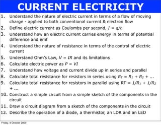
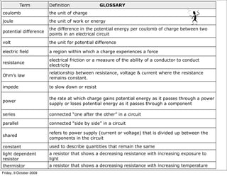
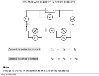
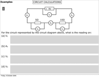
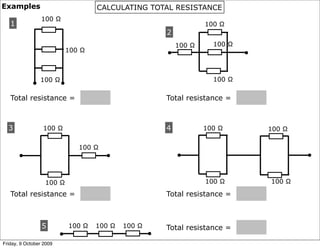
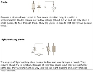
CURRENT ELECTRICITY
1.     Understand the nature of electric current in terms of a flow of moving
       charge - applied to both conventional current & electron flow
2.     Define electric current as Coulombs per second, I = q/t
3.     Understand how an electric current carries energy in terms of potential
       difference and emf
4.     Understand the nature of resistance in terms of the control of electric
       current
5.     Understand Ohm’s Law, V = IR and its limitations
6.     Calculate electric power as P = VI
7.     Understand how voltage and current divide up in series and parallel
8.     Calculate total resistance for resistors in series using RT = R1 + R2 + ...
9.     Calculate total resistance for resistors in parallel using RT = 1/R1 + 1/R2
       + ...
10. Construct a simple circuit from a simple sketch of the components in the
       circuit
11. Draw a circuit diagram from a sketch of the components in the circuit
12. Describe the operation of a diode, a thermistor, an LDR and an LED

Friday, 9 October 2009
Term          Definition               GLOSSARY
coulomb                  the unit of charge
joule                    the unit of work or energy
                         the difference in the potential energy per coulomb of charge between two
potential difference
                         points in an electrical circuit
volt                     the unit for potential difference

electric field           a region within which a charge experiences a force
                         electrical friction or a measure of the ability of a conductor to conduct
resistance
                         electricity
                         relationship between resistance, voltage & current where the resistance
Ohm’s law
                         remains constant.

impede                   to slow down or resist

                         the rate at which charge gains potential energy as it passes through a power
power
                         supply or loses potential energy as it passes through a component

series                   connected “one after the other” in a circuit

parallel                 connected “side by side” in a circuit

                         refers to power supply (current or voltage) that is divided up between the
shared
                         components in the circuit

constant                 used to describe quantities that remain the same
light dependent          a resistor that shows a decreasing resistance with increasing exposure to
resistor                 light
thermistor               a resistor that shows a decreasing resistance with increasing temperature
Friday, 9 October 2009
GO WITH THE FLOW !!

A SIMPLE CIRCUIT


Friday, 9 October 2009
DEFINING ELECTRIC CURRENT
Electron Flow
Electrons move through a lattice of metal ions as they flow (or bump their way)
towards the positive end of an electric field:


Conventional Current
The direction in which positive charge would flow Positive to Negative
Charges flow through wires under the influence of an electric field.


Note
(i) The electric field in a wire is uniform.
(ii) As charge flows in the field it loses potential energy.
(iii) The minimum potential energy that charge has is at the negative terminal of the
      power supply.
Friday, 9 October 2009
http://regentsprep.org/Regents/physics/
                                                     phys03/bsimplcir/default.htm


                                           1. What part of the model is like
                                              the power supply?
                                              ________________________
                                           2. What part of the model is like
                                              a component?
                                              ________________________

3. In the model, what are electric charges being likened to?   __________________

Conventional current is considered to be the flow of ____________ charges from
the __________ to the ____________ terminal of the power supply. Charges behave

like particles which have _____. When charge passes through a power supply it
______ electric potential energy in much the same way as particles (with mass) will
______ gravitational potential energy as they make their way up a slope. When
charge passes through a component it _______ electrical potential energy in much
the same way that particles (with mass) ______ gravitational potential energy as they

make their way down a slope. When charge moves around an electrical circuit it must
lose as much energy as it gains.
Friday, 9 October 2009
MATHEMATICALLY SPEAKING

Current -           is the rate of flow of electrical charge
        -           it is the number of coulombs of electrical charge that passes a point in
                    one second.

                                    where        I = electric current (Cs-1 or A)
                    I=Q
                                                 Q = electric charge (C)
                      t
                                                 t   = time (s)

   Note
   Cs-1 reads Coulomb per Second                                      V
                                                                  +       -
    Consider the simple circuit
                                                                               I
                                                          I


When voltage, V is increased the energy difference between a coulomb of charge on
either side of the power supply will increase. This energy difference drives electrons
around the circuit faster.

In other words, as supply voltage increases then current will also increase (provided
that the resistance remains constant)
Friday, 9 October 2009
Voltage         - is a measure of the energy used or produced by a component
                  (Common definition)

                - is the energy difference that a coulomb of charge has on either side of
                  a component (Formal definition)


Eg. Considering the voltage across a lamp:

                                              V
                                    +                   -

                                     A                 B
                                             1A


    If V = 6V then a coulomb of charge has 6J more electrical potential energy at
    point A than it does at point B


Unit of Voltage:         Joule per Coulomb or Volt
                         (JC-1)            or (V)


Note:
Potential Difference, p.d - a difference in voltage between parts of a circuit.
V = ∆Ep/q describes voltage mathematically as “difference in potential energy per unit
                                                     charge”
Friday, 9 October 2009
FACTORS THAT AFFECT RESISTANCE


      Also, some materials conduct electricity better than others Eg. Copper is better than iron
Friday, 9 October 2009
Do not copy                    THE VOLTAGE-CURRENT RATIO

 1. Consider a lamp in an electrical circuit:
                                                                 12V


                                                                         2A


12V represents the energy difference across the lamp. This drives electrons
through the lamp at the rate (or “speed”) of 2A. The voltage:current ratio is
_____

 2. Consider a different lamp in an electrical circuit:
                                                                 12V


                                                                         1A


This lamp has higher resistance because 12V across this lamp can only drive
electrons through the lamp at a rate of 1A. The voltage:current ratio is _____


       This example shows that the greater the voltage:current ratio then the greater the
       resistance is. Resistance is the voltage:current ratio

Friday, 9 October 2009
RESISTANCE
Definitions
1. Resistance, R is a measure of the “electrical friction” in a conductor. (the
   opposition to the flow of current)
2. It is the ratio of the voltage across a conductor to the current through it.


   Resistance = Voltage
                Current                           R=V
                                                           Unit of resistance is the ohm, Ω
                                                    I

       Resistance is given by the slope or gradient of a voltage - current graph


 Example
 In an experiment, the voltage across a lamp is measured and recorded as the current
 is increased 1 A at a time. Calculate the resistance of the lamp.

V (V)
     24
     20
     16
     12
     8
     4

          0   1   2   3   4   5   6
                                      I (A)
Friday, 9 October 2009
Example
What does each of the following graphs show about the resistance of the conductor?
                24                                         A conductor that retains a constant
1     V (V)     20                                         temperature as the current is increased:
                16
                12
                8
                4

                     0    1   2   3   4   5   6   I (A)


                                                           A conductor that is allowed to heat
                 24
2     V (V)                                                up as the current is increased
                 20
                 16
                 12
                 8
                 4
                                                   I (A)
                 0    1   2   3   4   5   6


                                                           A conductor that is cooled progressively
3     V (V)    24
               20                                          as the current is increased
               16
               12
               8
               4
                                                  I (A)
                 0    1   2   3   4   5   6
Friday, 9 October 2009
OHM’S LAW
Ohm’s Law states that the voltage across a resistor is proportional to the current
through it. i.e. V α I

A resistor that obeys Ohm’s Law has a voltage - current graph that is a straight line
so the resistance is always a constant value:


    V                                            Vα I

                                                 The gradient of the graph is R

                                                 So     V = RI

                                                 or

                                                 V = IR

                                 I
                                                 Ohm’s law is usually written this way

Note

Ohm’s law allows us to calculate the correct voltage when the current in the circuit
changes. This requires knowledge of the resistance and requires the value of the
resistance to stay the same regardless of the current.

A conductor which obeys Ohm’s Law is called an Ohmic conductor.
Friday, 9 October 2009
LIMITATIONS OF OHM’S LAW
         24
V (V)    20
                                                When a temperature of a lamp increases its
         16                                     resistance increases
         12
         8
         4
                                       I (A)
          0    1   2   3   4   5   6


For most conductors, as the temperature increases the increased vibration of particles
impedes the flow of electrons. Resistance in the conductor will therefore increase. The
graph slopes upwards.


V (V)    24
                                                The resistance of a thermistor decreases as its
         20
         16
                                                temperature decreases
         12
         8
         4
                                       I (A)
           0   1   2   3   4   5   6

                                                                                 Ex 16A: Q.1 to 4
Friday, 9 October 2009
POWER TO THE PEOPLE

Electrical power is the rate at which electrical work is done.

                                    P    =   W               Where    P = Power (W)
                                             t                        W = Work (J)
Units of power:           Joule per second or Watt                    t = time (s)
                               (Js-1)          (W)


The above expression for power is of limited use in electricity. The commonly used
formula is as follows:

               P     =   VI              Where     P = Power   (W)
                                                   V = Voltage (V)
                                                   I = Current (A)


Ohm’s Law states that V = I R. Substituting this into P = VI gives:                 P   =   I2R


Ohm’s Law also states that I = V .           Substituting this into P = VI gives:   P   =   V2
                               R                                                            R


Note: Work is done by a component because it changes electrical energy into other
      forms of energy
Friday, 9 October 2009
EXAMPLES                p167 ABA Q5 & 6

1. The diagrams opposite show two different heating
   circuits for a hot plate. Both circuits use two similar
   heating elements, A and B, of equal resistance.
(b) Draw a circuit diagram for each circuit.
                                                             240 V


                                                               240 V
(b) Consider circuit 1. The current flowing through
    element A is measured to be 1.2 A. What is the
    current through element B?
    _____________________________________
(c) How much current is drawn by circuit 1 from the mains?
    _________________________________________________________________
(d) Explain why the voltage across element A is 120 V.
    _________________________________________________________________
    _________________________________________________________________
(e) Calculate the resistance of each heating element.
    _________________________________________________________________
    _________________________________________________________________
Friday, 9 October 2009
Consider circuit 2
(h) Explain why the current through element A is 2.4 A.
    _________________________________________________________________
    _________________________________________________________________
(i) How much current is drawn from the mains?
    _________________________________________________________________
(j) Calculate how much electric power is turned to heat by the circuit.
    _________________________________________________________________
    _________________________________________________________________
(k) How may times more heat is generated in circuit 2 than in circuit 1.
    _________________________________________________________________


2. A stereo uses 240 V and the combined resistance of all its internal components is
   60Ω.
(c) Calculate the power rating of the stereo.
    __________________________________________________________________
(d) Calculate the amount of energy used to operate the stereo for half an hour.
    __________________________________________________________________
    __________________________________________________________________


                                                                    Ex 16E: Q.1 to 3
Friday, 9 October 2009
VOLTAGE AND CURRENT IN SERIES CIRCUITS


                                            +         -


                                                VT
                          A1                                           A3

                            I1                                     I3

                                           I2
                                                 A1


                                  V1                          V2


           Current in series is constant             I1   =   I2   =    I3


           Voltage in series is shared               VT   =   V1   +        V2

   Note
   Voltage is shared in proportion to the size of the resistance
Friday, 9 October 2009
PARALLEL CIRCUITS


                         +        -
                                                Current in parallel is shared
           IT                VT            IT
                                                IT   =     I1    +       I2
             I1                   R1
                                                in other words “charge splits
                                                up as it enters a junction in
                                                a circuit”
                             V1

             I2                   R2
                                                Voltage in parallel is constant

                             V2                 VT     =    V1       =    V2

 Note
 Current is shared in an inverse proportion to the size of the resistance.

 For example:
 If        R1 = 5 and R2 = 10
 and       IT = 3
 then      I1 = 2 and R2 = 1
Friday, 9 October 2009
http://phet.colorado.edu/simulations/   CIRCUIT CONSTRUCTION
         sims.php?
         sim=Circuit_Construction_Kit_DC_Only


1. Enter the URL (above) into the address bar of your internet browser.
2. Use the simulation tools to construct each of the following 3 circuits (ensure that you use
   identical lamps and an the same power supply for each circuit).
3. Record the current in each circuit and explain your observation.
4. Repeat this exercise for the second set of 3 circuits.

 1                                           2                          3
             +      -                               +    -                      +       -
                              A                               A                                 A


                                                                            3
                                                                                    +       -
                                             2
                                                                                                    A
     1                                               +   -

                 +       -                                    A

                                  A


Friday, 9 October 2009
Examples                      CIRCUIT CALCULATIONS


  1                                    + 9V -


                         A1               V1                  A3

                               5Ω                   10Ω
                                           A2


                                V2                   V3

For the circuit represented by the circuit diagram above, what is the reading on:
(a) V1


(b) A2


(c) V2


(d) V3


Friday, 9 October 2009
2                                      + 15V -

                                         V1

                                                        5Ω       A3
                           V2                 A1


                                                   V3
                            R                           10Ω
                                              A2


For the circuit represented by the circuit diagram above, what is the reading on:
(a) V3 if V2 = 10 V


(b) A1


(c) A2


(d) A3


(e) What is the value of resistor R?


Friday, 9 October 2009
3                                       + 12V -

                                           V1

                                                     2Ω     4.8Ω        V3
                                      A1


                                                V2
                                                     3Ω
                                      A2


For the circuit represented by the circuit diagram above, what is the reading on:

(a) V1


(b) V3


(c) V2


(d) A1


(e) A2

                                                                     Ex 16B: Q.1 to 3
Friday, 9 October 2009
RESISTANCE CALCULATIONS
Resistors which are connected end to end are in series with one
another
                               R1              R2


 The total resistance of the series combination, Rs is the sum of the
 resistances R1 and R2.

 For two or more resistors in series:         Rs = R1 + R2 + ...........


Resistors which are connected side by side are in parallel with each other.
                                         R1


                                         R2


 The total resistance of the parallel combination, Rp is less than any individual
 resistor in the combination.

 For two or more resistors in parallel           1    1    1 + ....
  the total resistance,Rp is given by:           RP = R1 + R2
Friday, 9 October 2009
Examples                             CALCULATING TOTAL RESISTANCE
                 100 Ω
   1                                                                 100 Ω
                                                         2
                                                             100 Ω     100 Ω
                             100 Ω                       •                     •


                 100 Ω                                                 100 Ω
             •           •
   Total resistance =                                    Total resistance =


  3              100 Ω                                   4           100 Ω         100 Ω

                                100 Ω
       •                                •                    •                             •


                  100 Ω                                              100 Ω         100 Ω

   Total resistance =                                    Total resistance =


                 5           100 Ω   100 Ω   100 Ω       Total resistance =
                         •                           •
Friday, 9 October 2009
Examples                        APPLIANCES IN THE HOME

1. A set of 10 Christmas tree lights operate from a 20 V supply. They are all similar
   1.0 W bulbs, connected in parallel.

(a) Calculate the voltage across each bulb.


(b) Calculate the current through each bulb, in mA.


(c) Calculate the resistance of each bulb.


(d) Calculate the total resistance in the circuit.


2. A 1000 W iron is connected to a 120 V supply. Should the iron need to be used on
   a 240V supply calculate the size of the resistance that will need to be added in
   series to the iron so that the iron continues to draw the same current.


                                                              Ex 16C: Q.3 & Ex 16E: Q.4 to 8
Friday, 9 October 2009
Examples/exercises                   DRAWING CIRCUIT DIAGRAMS


                                     Draw the following circuit diagrams in the space provided:


  1.
                         +   -


  2.
                         +   -


  3.                             A
                                              V

                         +   -


Friday, 9 October 2009
SPECIALIZED COMPONENTS


Thermistor


A thermistor is a resistor which is sensitive to heat. Unlike most resistors though its
resistance decreases as its temperature increases. This makes it useful in the circuit in
your car that contains the temperature gauge. The temperature gauge is an ammeter
calibrated to read temperature instead of Amps and the thermistor is in contact with
the engine and connected in series with the gauge. As the engine temperature
increases the resistance of the thermistor decreases thereby allowing the current in
the circuit to increase. This increase in current is reflected in the reading on the
gauge.


Light dependent resistor


An LDR is a resistor which is very sensitive to light. Its resistance decreases with light
intensity. They are useful in light meters where the meter is essentially an ammeter
re-calibrated to read lux instead of Amps.
Friday, 9 October 2009
Diode


Because a diode allows current to flow in one direction only, it is called a
semiconductor. Diodes require only a low voltage (about 0.6 V) and will only allow a
small current to flow through them. They are useful in circuits that convert AC current
to DC.


Light emitting diode


These give off light as they allow current to flow one way through a circuit. They
require about 2 V to function. Because of their low power input they are useful for
lights (eg. they are finding their way into the tail light clusters of motor vehicles)
Friday, 9 October 2009

11 - DC Electricity

  • 1.
    CURRENT ELECTRICITY 1. Understand the nature of electric current in terms of a flow of moving charge - applied to both conventional current & electron flow 2. Define electric current as Coulombs per second, I = q/t 3. Understand how an electric current carries energy in terms of potential difference and emf 4. Understand the nature of resistance in terms of the control of electric current 5. Understand Ohm’s Law, V = IR and its limitations 6. Calculate electric power as P = VI 7. Understand how voltage and current divide up in series and parallel 8. Calculate total resistance for resistors in series using RT = R1 + R2 + ... 9. Calculate total resistance for resistors in parallel using RT = 1/R1 + 1/R2 + ... 10. Construct a simple circuit from a simple sketch of the components in the circuit 11. Draw a circuit diagram from a sketch of the components in the circuit 12. Describe the operation of a diode, a thermistor, an LDR and an LED Friday, 9 October 2009
  • 2.
    Term Definition GLOSSARY coulomb the unit of charge joule the unit of work or energy the difference in the potential energy per coulomb of charge between two potential difference points in an electrical circuit volt the unit for potential difference electric field a region within which a charge experiences a force electrical friction or a measure of the ability of a conductor to conduct resistance electricity relationship between resistance, voltage & current where the resistance Ohm’s law remains constant. impede to slow down or resist the rate at which charge gains potential energy as it passes through a power power supply or loses potential energy as it passes through a component series connected “one after the other” in a circuit parallel connected “side by side” in a circuit refers to power supply (current or voltage) that is divided up between the shared components in the circuit constant used to describe quantities that remain the same light dependent a resistor that shows a decreasing resistance with increasing exposure to resistor light thermistor a resistor that shows a decreasing resistance with increasing temperature Friday, 9 October 2009
  • 3.
    GO WITH THEFLOW !! A SIMPLE CIRCUIT Friday, 9 October 2009
  • 4.
    DEFINING ELECTRIC CURRENT ElectronFlow Electrons move through a lattice of metal ions as they flow (or bump their way) towards the positive end of an electric field: Conventional Current The direction in which positive charge would flow Positive to Negative Charges flow through wires under the influence of an electric field. Note (i) The electric field in a wire is uniform. (ii) As charge flows in the field it loses potential energy. (iii) The minimum potential energy that charge has is at the negative terminal of the power supply. Friday, 9 October 2009
  • 5.
    http://regentsprep.org/Regents/physics/ phys03/bsimplcir/default.htm 1. What part of the model is like the power supply? ________________________ 2. What part of the model is like a component? ________________________ 3. In the model, what are electric charges being likened to? __________________ Conventional current is considered to be the flow of ____________ charges from the __________ to the ____________ terminal of the power supply. Charges behave like particles which have _____. When charge passes through a power supply it ______ electric potential energy in much the same way as particles (with mass) will ______ gravitational potential energy as they make their way up a slope. When charge passes through a component it _______ electrical potential energy in much the same way that particles (with mass) ______ gravitational potential energy as they make their way down a slope. When charge moves around an electrical circuit it must lose as much energy as it gains. Friday, 9 October 2009
  • 6.
    MATHEMATICALLY SPEAKING Current - is the rate of flow of electrical charge - it is the number of coulombs of electrical charge that passes a point in one second. where I = electric current (Cs-1 or A) I=Q Q = electric charge (C) t t = time (s) Note Cs-1 reads Coulomb per Second V + - Consider the simple circuit I I When voltage, V is increased the energy difference between a coulomb of charge on either side of the power supply will increase. This energy difference drives electrons around the circuit faster. In other words, as supply voltage increases then current will also increase (provided that the resistance remains constant) Friday, 9 October 2009
  • 7.
    Voltage - is a measure of the energy used or produced by a component (Common definition) - is the energy difference that a coulomb of charge has on either side of a component (Formal definition) Eg. Considering the voltage across a lamp: V + - A B 1A If V = 6V then a coulomb of charge has 6J more electrical potential energy at point A than it does at point B Unit of Voltage: Joule per Coulomb or Volt (JC-1) or (V) Note: Potential Difference, p.d - a difference in voltage between parts of a circuit. V = ∆Ep/q describes voltage mathematically as “difference in potential energy per unit charge” Friday, 9 October 2009
  • 8.
    FACTORS THAT AFFECTRESISTANCE Also, some materials conduct electricity better than others Eg. Copper is better than iron Friday, 9 October 2009
  • 9.
    Do not copy THE VOLTAGE-CURRENT RATIO 1. Consider a lamp in an electrical circuit: 12V 2A 12V represents the energy difference across the lamp. This drives electrons through the lamp at the rate (or “speed”) of 2A. The voltage:current ratio is _____ 2. Consider a different lamp in an electrical circuit: 12V 1A This lamp has higher resistance because 12V across this lamp can only drive electrons through the lamp at a rate of 1A. The voltage:current ratio is _____ This example shows that the greater the voltage:current ratio then the greater the resistance is. Resistance is the voltage:current ratio Friday, 9 October 2009
  • 10.
    RESISTANCE Definitions 1. Resistance, Ris a measure of the “electrical friction” in a conductor. (the opposition to the flow of current) 2. It is the ratio of the voltage across a conductor to the current through it. Resistance = Voltage Current R=V Unit of resistance is the ohm, Ω I Resistance is given by the slope or gradient of a voltage - current graph Example In an experiment, the voltage across a lamp is measured and recorded as the current is increased 1 A at a time. Calculate the resistance of the lamp. V (V) 24 20 16 12 8 4 0 1 2 3 4 5 6 I (A) Friday, 9 October 2009
  • 11.
    Example What does eachof the following graphs show about the resistance of the conductor? 24 A conductor that retains a constant 1 V (V) 20 temperature as the current is increased: 16 12 8 4 0 1 2 3 4 5 6 I (A) A conductor that is allowed to heat 24 2 V (V) up as the current is increased 20 16 12 8 4 I (A) 0 1 2 3 4 5 6 A conductor that is cooled progressively 3 V (V) 24 20 as the current is increased 16 12 8 4 I (A) 0 1 2 3 4 5 6 Friday, 9 October 2009
  • 12.
    OHM’S LAW Ohm’s Lawstates that the voltage across a resistor is proportional to the current through it. i.e. V α I A resistor that obeys Ohm’s Law has a voltage - current graph that is a straight line so the resistance is always a constant value: V Vα I The gradient of the graph is R So V = RI or V = IR I Ohm’s law is usually written this way Note Ohm’s law allows us to calculate the correct voltage when the current in the circuit changes. This requires knowledge of the resistance and requires the value of the resistance to stay the same regardless of the current. A conductor which obeys Ohm’s Law is called an Ohmic conductor. Friday, 9 October 2009
  • 13.
    LIMITATIONS OF OHM’SLAW 24 V (V) 20 When a temperature of a lamp increases its 16 resistance increases 12 8 4 I (A) 0 1 2 3 4 5 6 For most conductors, as the temperature increases the increased vibration of particles impedes the flow of electrons. Resistance in the conductor will therefore increase. The graph slopes upwards. V (V) 24 The resistance of a thermistor decreases as its 20 16 temperature decreases 12 8 4 I (A) 0 1 2 3 4 5 6 Ex 16A: Q.1 to 4 Friday, 9 October 2009
  • 14.
    POWER TO THEPEOPLE Electrical power is the rate at which electrical work is done. P = W Where P = Power (W) t W = Work (J) Units of power: Joule per second or Watt t = time (s) (Js-1) (W) The above expression for power is of limited use in electricity. The commonly used formula is as follows: P = VI Where P = Power (W) V = Voltage (V) I = Current (A) Ohm’s Law states that V = I R. Substituting this into P = VI gives: P = I2R Ohm’s Law also states that I = V . Substituting this into P = VI gives: P = V2 R R Note: Work is done by a component because it changes electrical energy into other forms of energy Friday, 9 October 2009
  • 15.
    EXAMPLES p167 ABA Q5 & 6 1. The diagrams opposite show two different heating circuits for a hot plate. Both circuits use two similar heating elements, A and B, of equal resistance. (b) Draw a circuit diagram for each circuit. 240 V 240 V (b) Consider circuit 1. The current flowing through element A is measured to be 1.2 A. What is the current through element B? _____________________________________ (c) How much current is drawn by circuit 1 from the mains? _________________________________________________________________ (d) Explain why the voltage across element A is 120 V. _________________________________________________________________ _________________________________________________________________ (e) Calculate the resistance of each heating element. _________________________________________________________________ _________________________________________________________________ Friday, 9 October 2009
  • 16.
    Consider circuit 2 (h)Explain why the current through element A is 2.4 A. _________________________________________________________________ _________________________________________________________________ (i) How much current is drawn from the mains? _________________________________________________________________ (j) Calculate how much electric power is turned to heat by the circuit. _________________________________________________________________ _________________________________________________________________ (k) How may times more heat is generated in circuit 2 than in circuit 1. _________________________________________________________________ 2. A stereo uses 240 V and the combined resistance of all its internal components is 60Ω. (c) Calculate the power rating of the stereo. __________________________________________________________________ (d) Calculate the amount of energy used to operate the stereo for half an hour. __________________________________________________________________ __________________________________________________________________ Ex 16E: Q.1 to 3 Friday, 9 October 2009
  • 17.
    VOLTAGE AND CURRENTIN SERIES CIRCUITS + - VT A1 A3 I1 I3 I2 A1 V1 V2 Current in series is constant I1 = I2 = I3 Voltage in series is shared VT = V1 + V2 Note Voltage is shared in proportion to the size of the resistance Friday, 9 October 2009
  • 18.
    PARALLEL CIRCUITS + - Current in parallel is shared IT VT IT IT = I1 + I2 I1 R1 in other words “charge splits up as it enters a junction in a circuit” V1 I2 R2 Voltage in parallel is constant V2 VT = V1 = V2 Note Current is shared in an inverse proportion to the size of the resistance. For example: If R1 = 5 and R2 = 10 and IT = 3 then I1 = 2 and R2 = 1 Friday, 9 October 2009
  • 19.
    http://phet.colorado.edu/simulations/ CIRCUIT CONSTRUCTION sims.php? sim=Circuit_Construction_Kit_DC_Only 1. Enter the URL (above) into the address bar of your internet browser. 2. Use the simulation tools to construct each of the following 3 circuits (ensure that you use identical lamps and an the same power supply for each circuit). 3. Record the current in each circuit and explain your observation. 4. Repeat this exercise for the second set of 3 circuits. 1 2 3 + - + - + - A A A 3 + - 2 A 1 + - + - A A Friday, 9 October 2009
  • 20.
    Examples CIRCUIT CALCULATIONS 1 + 9V - A1 V1 A3 5Ω 10Ω A2 V2 V3 For the circuit represented by the circuit diagram above, what is the reading on: (a) V1 (b) A2 (c) V2 (d) V3 Friday, 9 October 2009
  • 21.
    2 + 15V - V1 5Ω A3 V2 A1 V3 R 10Ω A2 For the circuit represented by the circuit diagram above, what is the reading on: (a) V3 if V2 = 10 V (b) A1 (c) A2 (d) A3 (e) What is the value of resistor R? Friday, 9 October 2009
  • 22.
    3 + 12V - V1 2Ω 4.8Ω V3 A1 V2 3Ω A2 For the circuit represented by the circuit diagram above, what is the reading on: (a) V1 (b) V3 (c) V2 (d) A1 (e) A2 Ex 16B: Q.1 to 3 Friday, 9 October 2009
  • 23.
    RESISTANCE CALCULATIONS Resistors whichare connected end to end are in series with one another R1 R2 The total resistance of the series combination, Rs is the sum of the resistances R1 and R2. For two or more resistors in series: Rs = R1 + R2 + ........... Resistors which are connected side by side are in parallel with each other. R1 R2 The total resistance of the parallel combination, Rp is less than any individual resistor in the combination. For two or more resistors in parallel 1 1 1 + .... the total resistance,Rp is given by: RP = R1 + R2 Friday, 9 October 2009
  • 24.
    Examples CALCULATING TOTAL RESISTANCE 100 Ω 1 100 Ω 2 100 Ω 100 Ω 100 Ω • • 100 Ω 100 Ω • • Total resistance = Total resistance = 3 100 Ω 4 100 Ω 100 Ω 100 Ω • • • • 100 Ω 100 Ω 100 Ω Total resistance = Total resistance = 5 100 Ω 100 Ω 100 Ω Total resistance = • • Friday, 9 October 2009
  • 25.
    Examples APPLIANCES IN THE HOME 1. A set of 10 Christmas tree lights operate from a 20 V supply. They are all similar 1.0 W bulbs, connected in parallel. (a) Calculate the voltage across each bulb. (b) Calculate the current through each bulb, in mA. (c) Calculate the resistance of each bulb. (d) Calculate the total resistance in the circuit. 2. A 1000 W iron is connected to a 120 V supply. Should the iron need to be used on a 240V supply calculate the size of the resistance that will need to be added in series to the iron so that the iron continues to draw the same current. Ex 16C: Q.3 & Ex 16E: Q.4 to 8 Friday, 9 October 2009
  • 26.
    Examples/exercises DRAWING CIRCUIT DIAGRAMS Draw the following circuit diagrams in the space provided: 1. + - 2. + - 3. A V + - Friday, 9 October 2009
  • 27.
    SPECIALIZED COMPONENTS Thermistor A thermistoris a resistor which is sensitive to heat. Unlike most resistors though its resistance decreases as its temperature increases. This makes it useful in the circuit in your car that contains the temperature gauge. The temperature gauge is an ammeter calibrated to read temperature instead of Amps and the thermistor is in contact with the engine and connected in series with the gauge. As the engine temperature increases the resistance of the thermistor decreases thereby allowing the current in the circuit to increase. This increase in current is reflected in the reading on the gauge. Light dependent resistor An LDR is a resistor which is very sensitive to light. Its resistance decreases with light intensity. They are useful in light meters where the meter is essentially an ammeter re-calibrated to read lux instead of Amps. Friday, 9 October 2009
  • 28.
    Diode Because a diodeallows current to flow in one direction only, it is called a semiconductor. Diodes require only a low voltage (about 0.6 V) and will only allow a small current to flow through them. They are useful in circuits that convert AC current to DC. Light emitting diode These give off light as they allow current to flow one way through a circuit. They require about 2 V to function. Because of their low power input they are useful for lights (eg. they are finding their way into the tail light clusters of motor vehicles) Friday, 9 October 2009