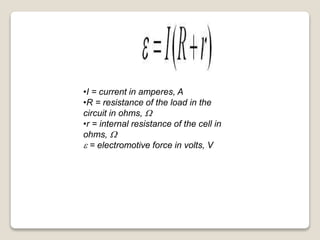
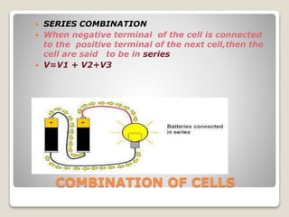
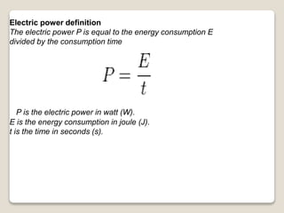
CURRENT ELECTRICITY
INTRODUCTION
Georg Simon Ohm (16
March 1789 – 6 July 1854)
was a German physicist and
mathematician. As a high
school teacher, Ohm began
his research with the new
electrochemical ceinvented
Using equipment of his own
creation, by Italian scientist
Alessandro VoltaOhm . found
that there is a direct
proportionality between the
potential difference (voltage)
applied across a conductor
and the resultant electric
current. This relationship is
known as Ohm's law.
ll,
OHM’S LAW
 So long as physicsl state of(material,dimension &temperature)
of a conductor remains constant, the electric current flowing
through the conductor is directly proportional to potential
difference applied across the conductor.
As per Ohm’s law V ∝ I
V=IR
This const is resistance of conductor & its S.I unit is
Ohm(Ω)
I=V/R or R= V/I
Reciprocal of resistance is conductance
G=1/R its S.I unit is mho or siemen
LIMITATION OF OHM’S LAW
 Ohm's law is not a fundamental law of nature.
There are a number of commonly used circuit
elements which do not obey this law. They have
one or more of the following properties:
 1. V depends on I non-linearly.
 2. The relationship between V and I depends on
the sign of V for the same absolute value of V.
 3. The relation between V and I is non-unique,
that is, for the same current I, there is more than
one value of voltage V.
The graph shows the
characteristics of a device known
as a thyristor, which consists of
four alternate layers of P and n-
type semiconductors. We find that
V is not directly proportional to I.
All the properties 1 to 3 are seen
and the region (PQ) is still more
interesting. Here the current
carried by the device increases as
the voltage decreases. Other
examples of non-ohmic devices are
electrolytes, thermistors.
RESISTANCE OF CONDUCTOR

The free electrons in a metal are in constant random
motion. As they move about they collide with each
other and with the atoms of the metal. If a potential
difference is now applied across the metal the
electrons tend to move towards the positive
connection..
The resistance of any conducting material depends
on the following factors:
(a) the material itself (actually how many free
electrons there are per metre cubed)
(b) its length
(c) its cross-sectional area and (d) its temperature
As they do so their progress is
interrupted by collisions. These
collisions impede their movement and
this property of the material is called
its resistance. If the temperature of
the metal is raised the atoms vibrate
more strongly and the electrons
make more violent collisions with
them and so the resistance of the
metal increase
The resistance of a given piece of material is
connected to the current flowing through it and
the potential difference between its ends by the
equation:
Resistance (R) = Potential Difference (V)/ Current
(I)
The units of resistance are ohms .
DRIFT VELOCITY
 The definition of drift velocity can be
understood by imagining the random motion of
free electrons inside a conductor. The free
electrons inside a conductor moves with
random velocities and in random directions.
When an electric field is applied across the
conductor the randomly moving electrons are
subjected to electrical forces along the
direction of the field.
Due to this field, the electrons do not give up their
randomness of motion but they will be shifting
towards higher potential. That means the electrons
will drift towards higher potential along with their
random motions. Thus every electron will have a
net velocity towards higher potential end of the
conductor and this net velocity is referred as drift
velocity of electrons. The current due to this drift
movement of electrons inside an electrically
stressed conductor, is known as drift current. It is
need less to say that every electric current flows
through conductor is drift current
SPECIFIC RESISTANCE
 Specific resistance definition:
 The specific electrical resistance of a conductor depends
on its material and temperature. The Amount of
resistance in the flow of current, cross sectional area is
called specific resistance of that conductor.
Many resistors and conductors have a uniform
cross section with a uniform flow of electric
current and are made of one material.
where
R is the electrical resistance of a uniform
specimen of the material (measured
in ohms, Ω)
l is the length of the piece of material
(measured in metres, m)
A is the cross-sectional area of the
specimen (measured in square metres,
m2).
l
the electrical resistivity ρ (Greek:
rho) is defined as:
.
if and (forming a cube with perfectly-conductive contacts on
opposite faces), then the resistance of this element in ohms is
numerically equal to the resistivity of the material it is made of in
ohm-meters. Likewise, a 1 ohm⋅cm material would have a
resistance of 1 ohm if contacted on opposite faces of a
1 cm×1 cm×1 cm cube.
Conductivity σ (Greek: sigma) is defined as
the inverse of resistivity:
Conductivity has SI units of siemens per
meter (S/m).
TABLE OF RESISTIVITY FOR SOME
MATERIALS
Material ρ (Ω•m) at 20 °C
Resistivity
σ (S/m) at 20 °C
Conductivity
Silver 1.59×10
−8
6.30×10
7
Copper 1.68×10
−8
5.96×10
7
Annealed copper 1.72×10
−8
5.80×10
7
Gold 2.44×10
−8
4.10×10
7
Aluminum 2.82×10
−8
3.5×10
7
Calcium 3.36×10
−8
2.98×10
7
Tungsten 5.60×10
−8
1.79×10
7
Zinc 5.90×10
−8
1.69×10
7
RESISTIVITY
CONDUCTOR
INSULATOR
SEMICONDUCTORS
CLASSIFICATION
TEMPERATURE DEPENDENCE OF
RESISTANCE
The temperature coefficient of resistance is a
number used to predict how the resistance of a
material changes with changes in temperature.
Typically the units are either resistance per
temperature or 1/temperature depending on which
equation is used for the calculations. For example, in
copper the temperature coefficient of resistance is
about 0.0039 per change in degrees Celsius. A
positive temperature coefficient of resistance means
that the resistance of the material will increase as
temperature increases.
As per the equation or say unit of
resistance temperature coefficient, its
definition can be given as below:
" Rise in temperature per unit initial
resistance, when temperature is raised
by one degree Celsius is called the
resistance temperature coefficient."
DERIVATION OF TEMPERATURE
DEPENDENCE OF RESISTIVITY
 The factor by which the resistance of the object changes when
changing it’s temperature is called the Temperature coefficient
of resistance , Let us derive an mathematical expression and
more precise definition of it here:

 Let a conductor have a resistance of initially at 0, Latter let the
conductor be heated up to t and let it’s resistance at be Rt.
 Then the change in the temperature is: t-0
 and the change in it’s resistance is: Rt-Ro
 it is obvious that the change in resistance depends on following
factors:
 1. Directly on it’s initial resistance.
 2. Directly on rise in temperature.
 3. On the nature of material by which the conductor is made up
of.

...Read more http://electronicspani.com/temperature-coefficient-of-resistance/
Here the symbol alpha is a constant multiplier and is known as
the temperature coefficient of resistance of the conductor.
Solving the equation we get:
… /
...Read more http://electronicspani.com/temperature-coefficient-of-resistance/
Thus the exact definition of the temperature
coefficient of resistance is:
The increase in resistance per ohm original
temperature per degree Celsius change in
temperature.
Using the formulas derived above and
the definition we can find the exact resistance of a
substance at any temperature with the following
formula:
/
/
It should be noted that all the formulas
derived here are equally true for both rise
as well as fall in temperature.
As temperature of a conductor increases it’s
resistance increases and and as thee
temperature of conductor is decreased the
resistance is also decreases.
GRAPH OF RESISTIVITY VERSUS
TEMPERATURE
GRAPH OF RESISTIVITY VERSUS
TEMPERATURE FOR DIFFERENT
MATERIALS
THERMISTOR
 Thermistors are temperature
sensitive resistors. All resistors
vary with temperature, but
thermistors are constructed of
semiconductor material with a
resistivity that is especially
sensitive to
temperature. However, unlike
most other resistive devices, the
resistance of a thermistor
decreases with increasing
temperature. That's due to the
properties of the semiconductor
material that the thermistor is
made from.
Types of Thermistors:
There are mainly 2 types of
thermistors namely Positive-
temperature coefficient (PTC) and
Negative-temperature coefficient
(NTC).
CHARACTERISTICS
 As just mentioned above, resistance increase with increase
in temperature for PTC and resistance decrease with
increase in temperature for NTC.
 The thermistor exhibits a highly non-linear characteristic of
resistance vs temperature.
SUPERCONDUCTIVITY
 Superconductivity is a
phenomenon of exactly
zero electrical resistance
and expulsion of
magnetic fields occurring
in certain materials when
cooled below a
characteristic critical
temperature. It was
discovered by Dutch
physicist Heike
Kamerlingh Onnes on
April 8, 1911 in Leiden
 DEFINITION:
 The ability of certain metals or
alloys to conduct an electric
current with almost no resistance.
Superconductivity usually occurs
close to absolute zero, at
temperatures approaching -
459.67°F (-273.15°C), but has
also been observed at
temperatures as high as -200°F (-
128.88°C)
Critical temperature
 1. The temperature of a substance at its
critical point.
 2. The temperature at which a material
becomes a superconductor.
 3. The temperature at which a property of
a material, such as its magnetism, change
COLOR CODE OF CARBON RESISTOR
TABLE OF COLOR CODE
EXAMPLE
DEFINITION OF EMF AND P.D
 The emf of a cell is defined as the
work done or energy spent in
moving a unit positive charge from
its negative terminal to its positive
terminal.
Potential difference is defined as
the difference in electrical charge
between two points in a circuit
expressed in volts
Electromotive Force and
Internal Resistance
 The electromotive force (e) or e.m.f. is the
energy provided by a cell or battery per
coulomb of charge passing through it, it is
measured in volts (V). It is equal to the
potential difference across the terminals of
the cell when no current is flowing.
•E = energy in joules, J
e = electromotive force in volts, V
•Q = charge in coulombs, C
Batteries and cells have an internal resistance (r)
which is measures in ohm’s (W). When electricity
flows round a circuit the internal resistance of the cell
itself resists the flow of current and so thermal
(heat) energy is wasted in the cell itself.
•I = current in amperes, A
•R = resistance of the load in the
circuit in ohms, W
•r = internal resistance of the cell in
ohms, W
e = electromotive force in volts, V
We can rearrange the above equation;
and then to
In this equation (V) appears which is the terminal
potential difference, measured in volts (V). This is
the potential difference across the terminals of the
cell when current is flowing in the circuit, it is
always less than the e.m.f. of the cell. -
COMBINATION OF CELLS
 SERIES COMBINATION
 When negative terminal of the cell is connected
to the positive terminal of the next cell,then the
cell are said to be in series
 V=V1 + V2+V3
PARALLEL COMBINATION
Cells are said to be connected in
parallel when they are joined
positive to positive and negative to
negative such that current is
divided between the cells.
I=I1+I2+I3
WORK DONE BY ELECTRIC
CIRCUIT
 Definition:-
 This law states that heat
produced by resistor directly depend upon
power and time.

OR
 This law states that heat produced by
resistor directly depend upon current
square I2, resistance R and time t.

W= (potential difference) * (charge)
W= V*I*t ---------------------(since,
I=q/t)
H= W= I2Rt ----------
Equation1 (since, V=IR)
JOULE’S LAW
 Joule’s law, in electricity,
mathematical description of the
rate at which resistance in a
circuit converts electric energy
into heat energy. The English
physicist James Prescott Joule
discovered in 1840 that the
amount of heat per second that
develops in a wire carrying a
current is proportional to the
electrical resistance of the wire
and the square of the current. He
determined that the heat evolved
per second is equivalent to the
electric power absorbed, or the
power loss.
 When a current of I amperes passes through a circuit of
resistance R ohms for a time of t seconds then the heat
produced is given by the relation.
 H=I2Rt joules
 The above relation is known as the joule’s law of heating.
It states that the heat produced is proportional to
 1. Square of the current I.
 2. Resistance of the circuit R.
 3. The time t during which the current flows through
the circuit.
 Heat produced in calories can be expressed as
 H=I2Rt/4.18
Calories
 (1 calorie=4.18 joule)




POWER IN AN ELECTRIC CIRCUIT
 Electric power, like mechanical power, is the rate
of doing work, measured in watts, and
represented by the letter P. The term wattage is
used colloquially to mean "electric power in
watts." The electric power in watts produced by
an electric current I consisting of a charge of Q
coulombs every t seconds passing through an
electric potential (voltage) difference of V is
 where
 Q is electric charge in coulombs t is time in
seconds I is electric current in amperes V is
electric potential or voltage in volts
Electric power definition
The electric power P is equal to the energy consumption E
divided by the consumption time
P is the electric power in watt (W).
E is the energy consumption in joule (J).
t is the time in seconds (s).
horsepower - a unit of power equal to
746 watts H.P., HP
power unit - a measure of electric power
watt, W - a unit of power equal to 1 joule
per second; the power dissipated by a
current of 1 ampere flowing across a
resistance of 1 ohm
Current   electricity

Current electricity

  • 1.
  • 2.
    INTRODUCTION Georg Simon Ohm(16 March 1789 – 6 July 1854) was a German physicist and mathematician. As a high school teacher, Ohm began his research with the new electrochemical ceinvented Using equipment of his own creation, by Italian scientist Alessandro VoltaOhm . found that there is a direct proportionality between the potential difference (voltage) applied across a conductor and the resultant electric current. This relationship is known as Ohm's law. ll,
  • 3.
    OHM’S LAW  Solong as physicsl state of(material,dimension &temperature) of a conductor remains constant, the electric current flowing through the conductor is directly proportional to potential difference applied across the conductor. As per Ohm’s law V ∝ I V=IR This const is resistance of conductor & its S.I unit is Ohm(Ω) I=V/R or R= V/I Reciprocal of resistance is conductance G=1/R its S.I unit is mho or siemen
  • 4.
    LIMITATION OF OHM’SLAW  Ohm's law is not a fundamental law of nature. There are a number of commonly used circuit elements which do not obey this law. They have one or more of the following properties:  1. V depends on I non-linearly.  2. The relationship between V and I depends on the sign of V for the same absolute value of V.  3. The relation between V and I is non-unique, that is, for the same current I, there is more than one value of voltage V.
  • 5.
    The graph showsthe characteristics of a device known as a thyristor, which consists of four alternate layers of P and n- type semiconductors. We find that V is not directly proportional to I. All the properties 1 to 3 are seen and the region (PQ) is still more interesting. Here the current carried by the device increases as the voltage decreases. Other examples of non-ohmic devices are electrolytes, thermistors.
  • 6.
    RESISTANCE OF CONDUCTOR  Thefree electrons in a metal are in constant random motion. As they move about they collide with each other and with the atoms of the metal. If a potential difference is now applied across the metal the electrons tend to move towards the positive connection..
  • 7.
    The resistance ofany conducting material depends on the following factors: (a) the material itself (actually how many free electrons there are per metre cubed) (b) its length (c) its cross-sectional area and (d) its temperature As they do so their progress is interrupted by collisions. These collisions impede their movement and this property of the material is called its resistance. If the temperature of the metal is raised the atoms vibrate more strongly and the electrons make more violent collisions with them and so the resistance of the metal increase
  • 8.
    The resistance ofa given piece of material is connected to the current flowing through it and the potential difference between its ends by the equation: Resistance (R) = Potential Difference (V)/ Current (I) The units of resistance are ohms .
  • 9.
    DRIFT VELOCITY  Thedefinition of drift velocity can be understood by imagining the random motion of free electrons inside a conductor. The free electrons inside a conductor moves with random velocities and in random directions. When an electric field is applied across the conductor the randomly moving electrons are subjected to electrical forces along the direction of the field.
  • 10.
    Due to thisfield, the electrons do not give up their randomness of motion but they will be shifting towards higher potential. That means the electrons will drift towards higher potential along with their random motions. Thus every electron will have a net velocity towards higher potential end of the conductor and this net velocity is referred as drift velocity of electrons. The current due to this drift movement of electrons inside an electrically stressed conductor, is known as drift current. It is need less to say that every electric current flows through conductor is drift current
  • 11.
    SPECIFIC RESISTANCE  Specificresistance definition:  The specific electrical resistance of a conductor depends on its material and temperature. The Amount of resistance in the flow of current, cross sectional area is called specific resistance of that conductor. Many resistors and conductors have a uniform cross section with a uniform flow of electric current and are made of one material.
  • 12.
    where R is theelectrical resistance of a uniform specimen of the material (measured in ohms, Ω) l is the length of the piece of material (measured in metres, m) A is the cross-sectional area of the specimen (measured in square metres, m2). l the electrical resistivity ρ (Greek: rho) is defined as:
  • 13.
    . if and (forminga cube with perfectly-conductive contacts on opposite faces), then the resistance of this element in ohms is numerically equal to the resistivity of the material it is made of in ohm-meters. Likewise, a 1 ohm⋅cm material would have a resistance of 1 ohm if contacted on opposite faces of a 1 cm×1 cm×1 cm cube. Conductivity σ (Greek: sigma) is defined as the inverse of resistivity: Conductivity has SI units of siemens per meter (S/m).
  • 14.
    TABLE OF RESISTIVITYFOR SOME MATERIALS Material ρ (Ω•m) at 20 °C Resistivity σ (S/m) at 20 °C Conductivity Silver 1.59×10 −8 6.30×10 7 Copper 1.68×10 −8 5.96×10 7 Annealed copper 1.72×10 −8 5.80×10 7 Gold 2.44×10 −8 4.10×10 7 Aluminum 2.82×10 −8 3.5×10 7 Calcium 3.36×10 −8 2.98×10 7 Tungsten 5.60×10 −8 1.79×10 7 Zinc 5.90×10 −8 1.69×10 7
  • 15.
  • 16.
    TEMPERATURE DEPENDENCE OF RESISTANCE Thetemperature coefficient of resistance is a number used to predict how the resistance of a material changes with changes in temperature. Typically the units are either resistance per temperature or 1/temperature depending on which equation is used for the calculations. For example, in copper the temperature coefficient of resistance is about 0.0039 per change in degrees Celsius. A positive temperature coefficient of resistance means that the resistance of the material will increase as temperature increases.
  • 17.
    As per theequation or say unit of resistance temperature coefficient, its definition can be given as below: " Rise in temperature per unit initial resistance, when temperature is raised by one degree Celsius is called the resistance temperature coefficient."
  • 18.
    DERIVATION OF TEMPERATURE DEPENDENCEOF RESISTIVITY  The factor by which the resistance of the object changes when changing it’s temperature is called the Temperature coefficient of resistance , Let us derive an mathematical expression and more precise definition of it here:   Let a conductor have a resistance of initially at 0, Latter let the conductor be heated up to t and let it’s resistance at be Rt.  Then the change in the temperature is: t-0  and the change in it’s resistance is: Rt-Ro  it is obvious that the change in resistance depends on following factors:  1. Directly on it’s initial resistance.  2. Directly on rise in temperature.  3. On the nature of material by which the conductor is made up of. 
  • 19.
    ...Read more http://electronicspani.com/temperature-coefficient-of-resistance/ Herethe symbol alpha is a constant multiplier and is known as the temperature coefficient of resistance of the conductor. Solving the equation we get: … / ...Read more http://electronicspani.com/temperature-coefficient-of-resistance/
  • 20.
    Thus the exactdefinition of the temperature coefficient of resistance is: The increase in resistance per ohm original temperature per degree Celsius change in temperature. Using the formulas derived above and the definition we can find the exact resistance of a substance at any temperature with the following formula: / /
  • 21.
    It should benoted that all the formulas derived here are equally true for both rise as well as fall in temperature. As temperature of a conductor increases it’s resistance increases and and as thee temperature of conductor is decreased the resistance is also decreases.
  • 22.
    GRAPH OF RESISTIVITYVERSUS TEMPERATURE
  • 23.
    GRAPH OF RESISTIVITYVERSUS TEMPERATURE FOR DIFFERENT MATERIALS
  • 24.
    THERMISTOR  Thermistors aretemperature sensitive resistors. All resistors vary with temperature, but thermistors are constructed of semiconductor material with a resistivity that is especially sensitive to temperature. However, unlike most other resistive devices, the resistance of a thermistor decreases with increasing temperature. That's due to the properties of the semiconductor material that the thermistor is made from.
  • 25.
    Types of Thermistors: Thereare mainly 2 types of thermistors namely Positive- temperature coefficient (PTC) and Negative-temperature coefficient (NTC).
  • 26.
    CHARACTERISTICS  As justmentioned above, resistance increase with increase in temperature for PTC and resistance decrease with increase in temperature for NTC.  The thermistor exhibits a highly non-linear characteristic of resistance vs temperature.
  • 27.
    SUPERCONDUCTIVITY  Superconductivity isa phenomenon of exactly zero electrical resistance and expulsion of magnetic fields occurring in certain materials when cooled below a characteristic critical temperature. It was discovered by Dutch physicist Heike Kamerlingh Onnes on April 8, 1911 in Leiden
  • 28.
     DEFINITION:  Theability of certain metals or alloys to conduct an electric current with almost no resistance. Superconductivity usually occurs close to absolute zero, at temperatures approaching - 459.67°F (-273.15°C), but has also been observed at temperatures as high as -200°F (- 128.88°C)
  • 29.
    Critical temperature  1.The temperature of a substance at its critical point.  2. The temperature at which a material becomes a superconductor.  3. The temperature at which a property of a material, such as its magnetism, change
  • 30.
    COLOR CODE OFCARBON RESISTOR
  • 31.
  • 32.
  • 33.
    DEFINITION OF EMFAND P.D  The emf of a cell is defined as the work done or energy spent in moving a unit positive charge from its negative terminal to its positive terminal. Potential difference is defined as the difference in electrical charge between two points in a circuit expressed in volts
  • 34.
    Electromotive Force and InternalResistance  The electromotive force (e) or e.m.f. is the energy provided by a cell or battery per coulomb of charge passing through it, it is measured in volts (V). It is equal to the potential difference across the terminals of the cell when no current is flowing. •E = energy in joules, J e = electromotive force in volts, V •Q = charge in coulombs, C
  • 35.
    Batteries and cellshave an internal resistance (r) which is measures in ohm’s (W). When electricity flows round a circuit the internal resistance of the cell itself resists the flow of current and so thermal (heat) energy is wasted in the cell itself.
  • 36.
    •I = currentin amperes, A •R = resistance of the load in the circuit in ohms, W •r = internal resistance of the cell in ohms, W e = electromotive force in volts, V
  • 37.
    We can rearrangethe above equation; and then to In this equation (V) appears which is the terminal potential difference, measured in volts (V). This is the potential difference across the terminals of the cell when current is flowing in the circuit, it is always less than the e.m.f. of the cell. -
  • 38.
    COMBINATION OF CELLS SERIES COMBINATION  When negative terminal of the cell is connected to the positive terminal of the next cell,then the cell are said to be in series  V=V1 + V2+V3
  • 39.
    PARALLEL COMBINATION Cells aresaid to be connected in parallel when they are joined positive to positive and negative to negative such that current is divided between the cells. I=I1+I2+I3
  • 40.
    WORK DONE BYELECTRIC CIRCUIT  Definition:-  This law states that heat produced by resistor directly depend upon power and time.  OR  This law states that heat produced by resistor directly depend upon current square I2, resistance R and time t. 
  • 41.
    W= (potential difference)* (charge) W= V*I*t ---------------------(since, I=q/t) H= W= I2Rt ---------- Equation1 (since, V=IR)
  • 42.
    JOULE’S LAW  Joule’slaw, in electricity, mathematical description of the rate at which resistance in a circuit converts electric energy into heat energy. The English physicist James Prescott Joule discovered in 1840 that the amount of heat per second that develops in a wire carrying a current is proportional to the electrical resistance of the wire and the square of the current. He determined that the heat evolved per second is equivalent to the electric power absorbed, or the power loss.
  • 43.
     When acurrent of I amperes passes through a circuit of resistance R ohms for a time of t seconds then the heat produced is given by the relation.  H=I2Rt joules  The above relation is known as the joule’s law of heating. It states that the heat produced is proportional to  1. Square of the current I.  2. Resistance of the circuit R.  3. The time t during which the current flows through the circuit.  Heat produced in calories can be expressed as  H=I2Rt/4.18 Calories  (1 calorie=4.18 joule)    
  • 44.
    POWER IN ANELECTRIC CIRCUIT  Electric power, like mechanical power, is the rate of doing work, measured in watts, and represented by the letter P. The term wattage is used colloquially to mean "electric power in watts." The electric power in watts produced by an electric current I consisting of a charge of Q coulombs every t seconds passing through an electric potential (voltage) difference of V is  where  Q is electric charge in coulombs t is time in seconds I is electric current in amperes V is electric potential or voltage in volts
  • 45.
    Electric power definition Theelectric power P is equal to the energy consumption E divided by the consumption time P is the electric power in watt (W). E is the energy consumption in joule (J). t is the time in seconds (s).
  • 46.
    horsepower - aunit of power equal to 746 watts H.P., HP power unit - a measure of electric power watt, W - a unit of power equal to 1 joule per second; the power dissipated by a current of 1 ampere flowing across a resistance of 1 ohm