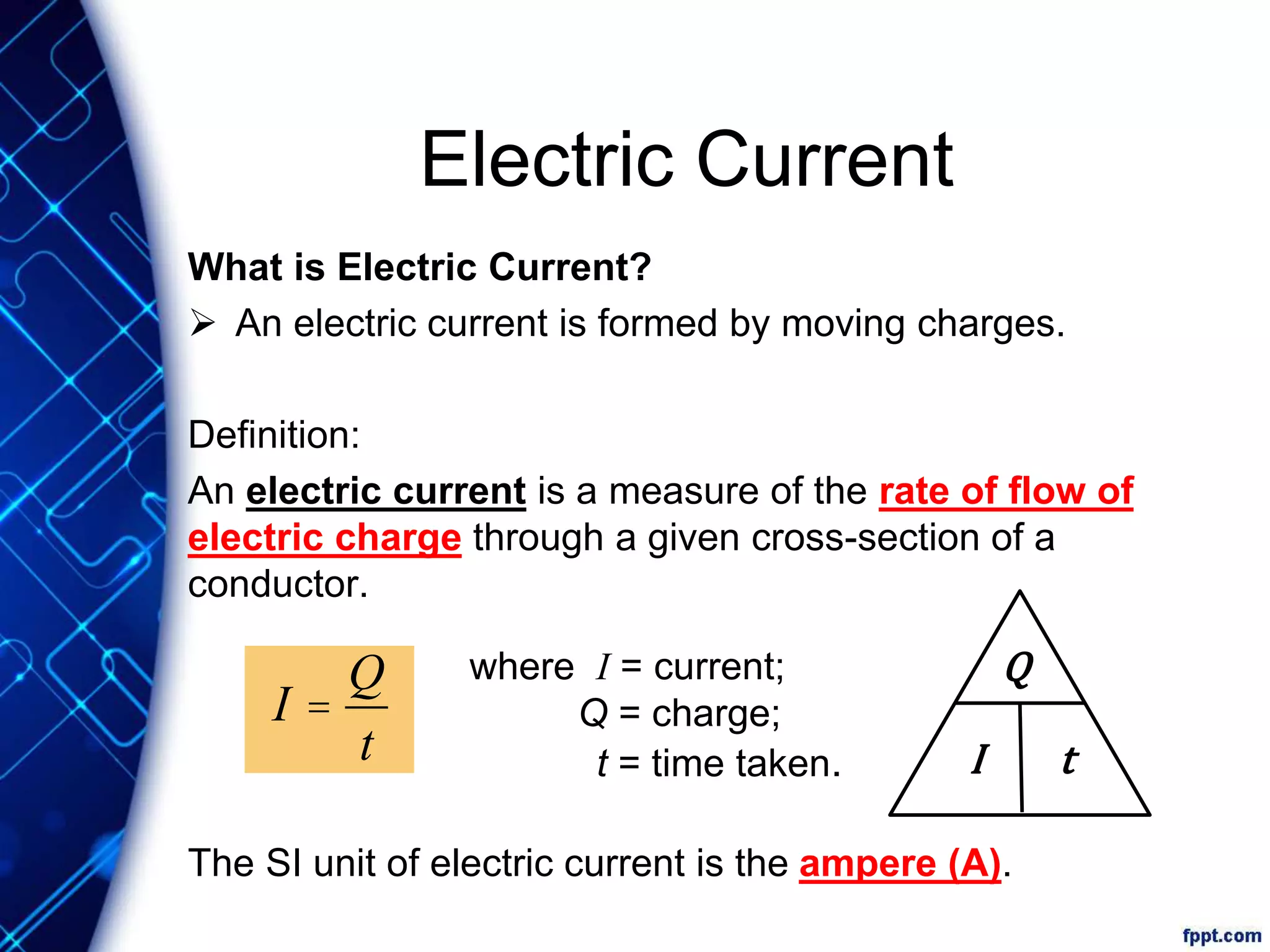
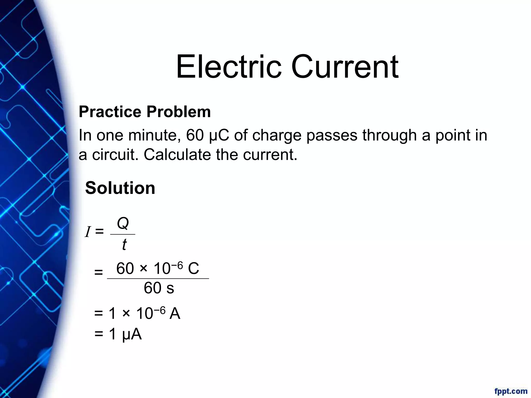
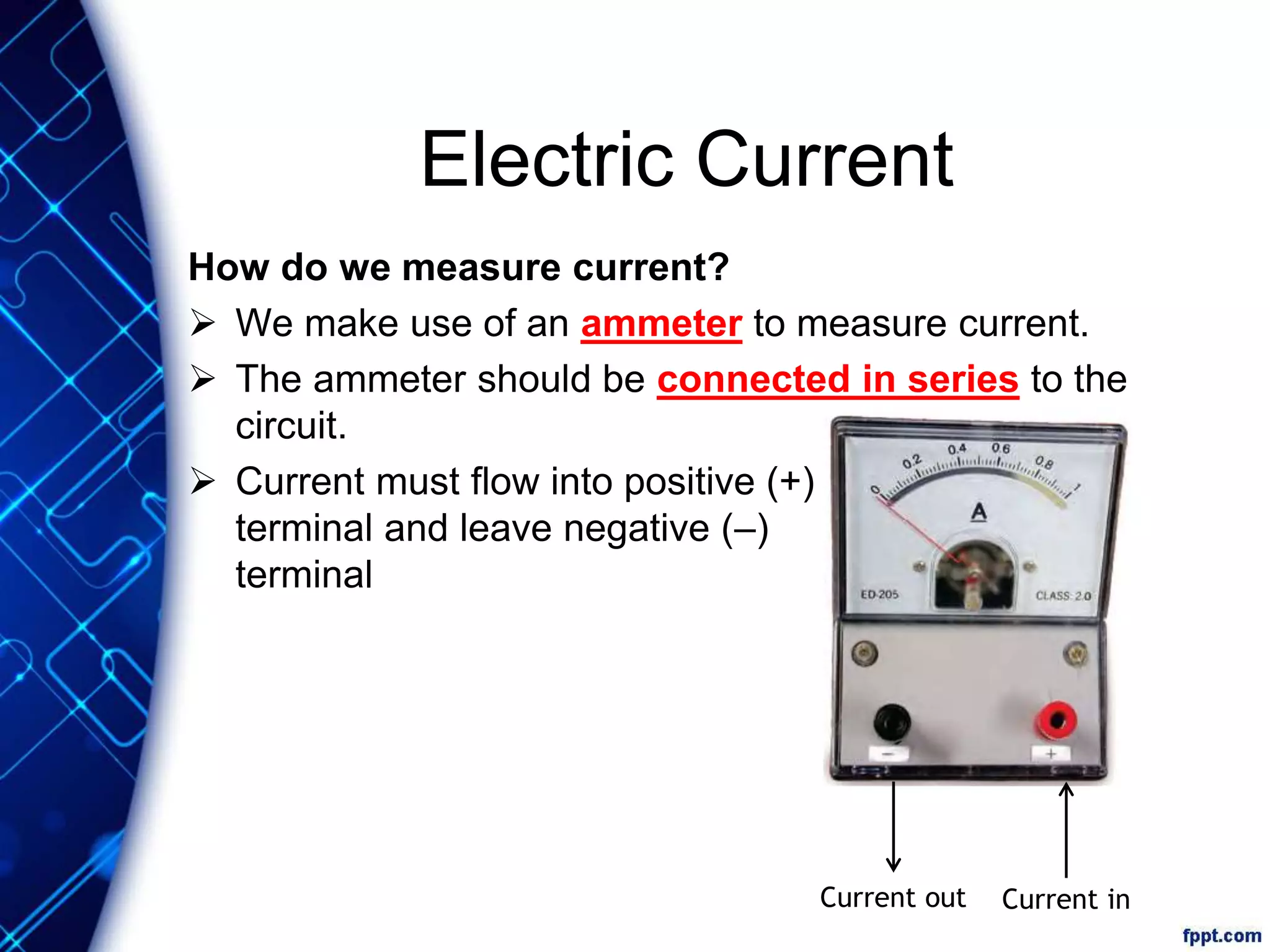
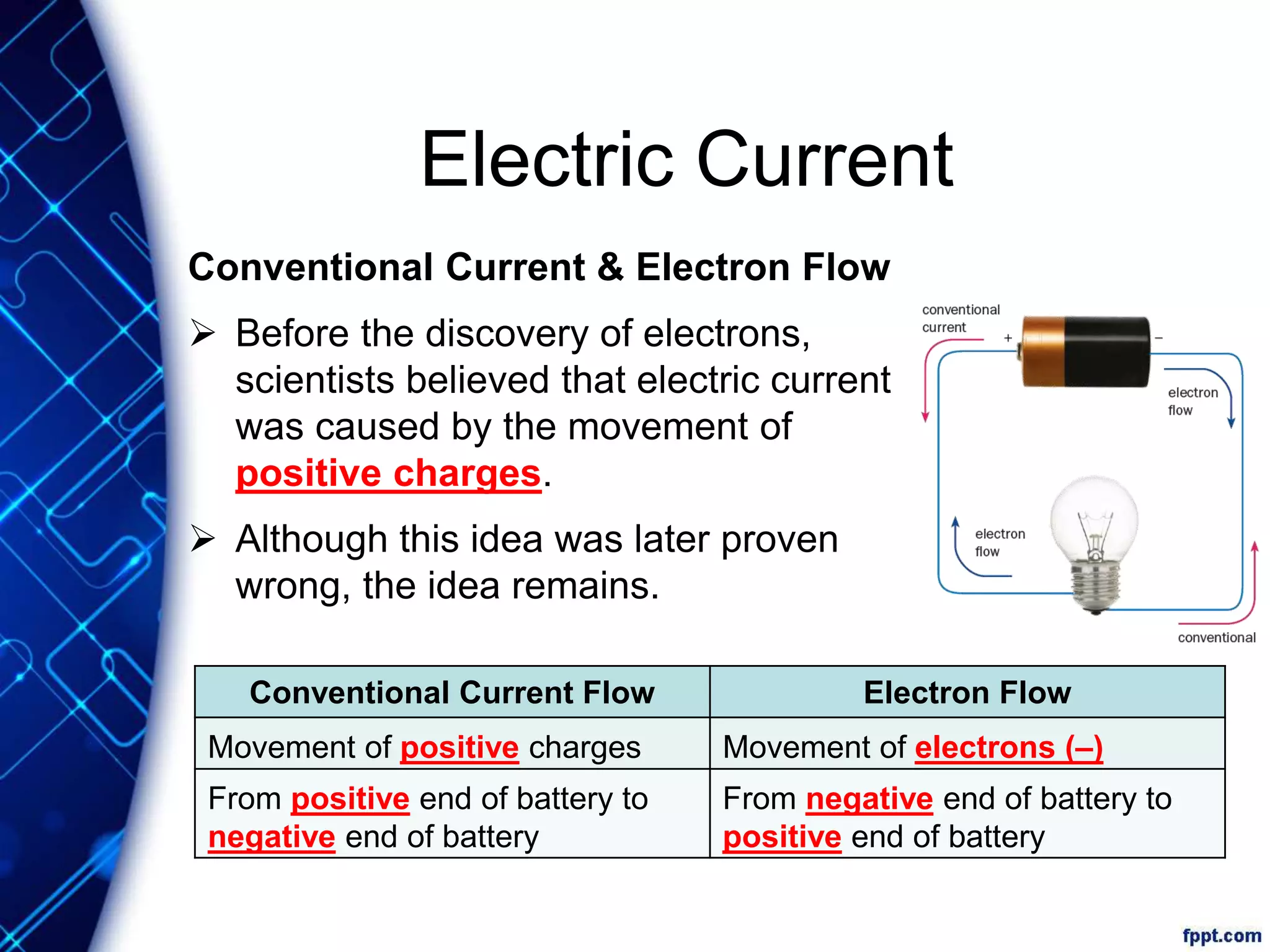
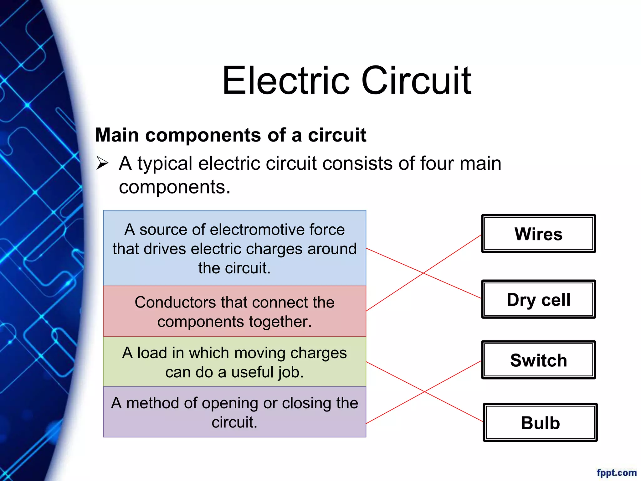
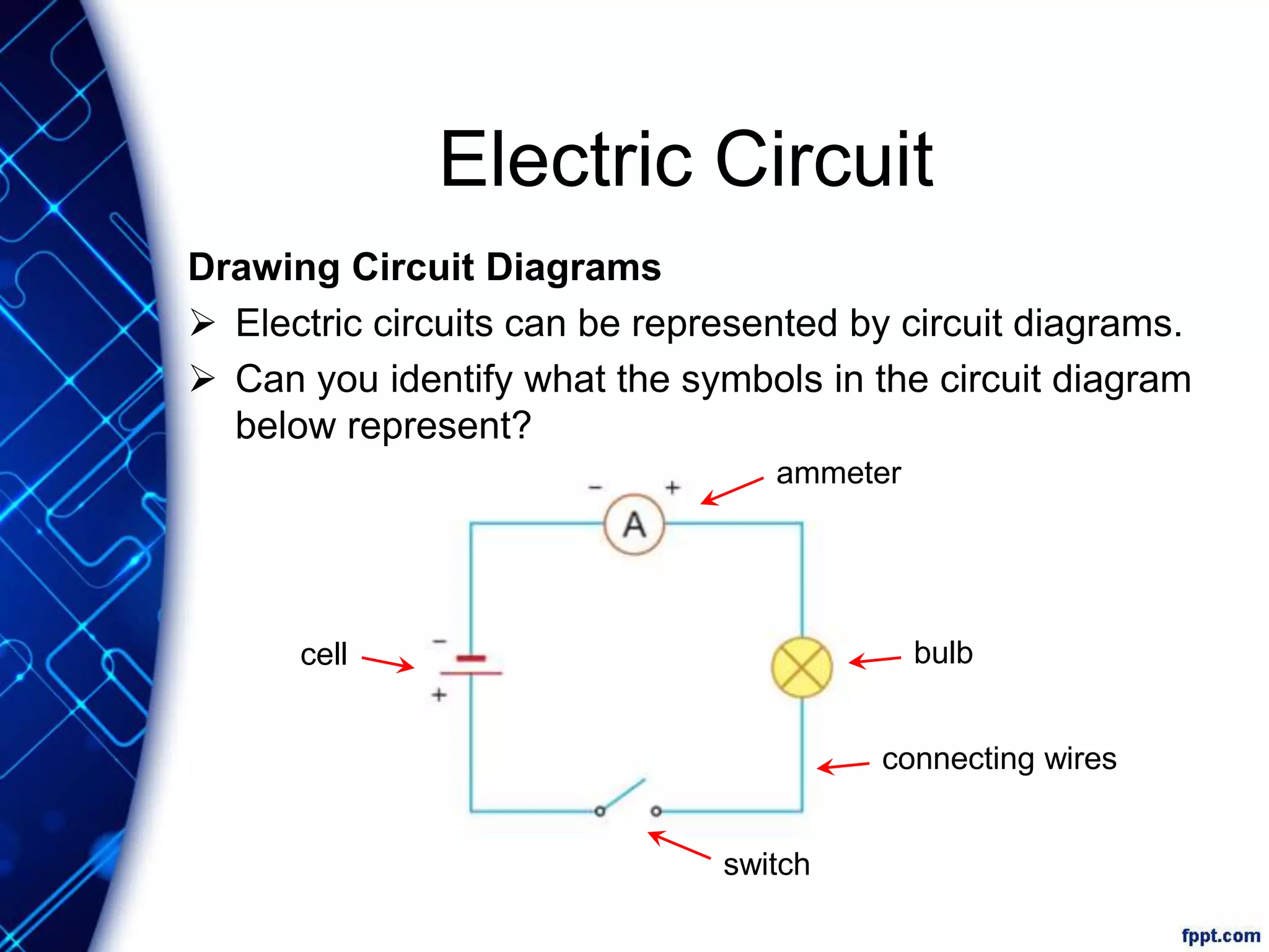
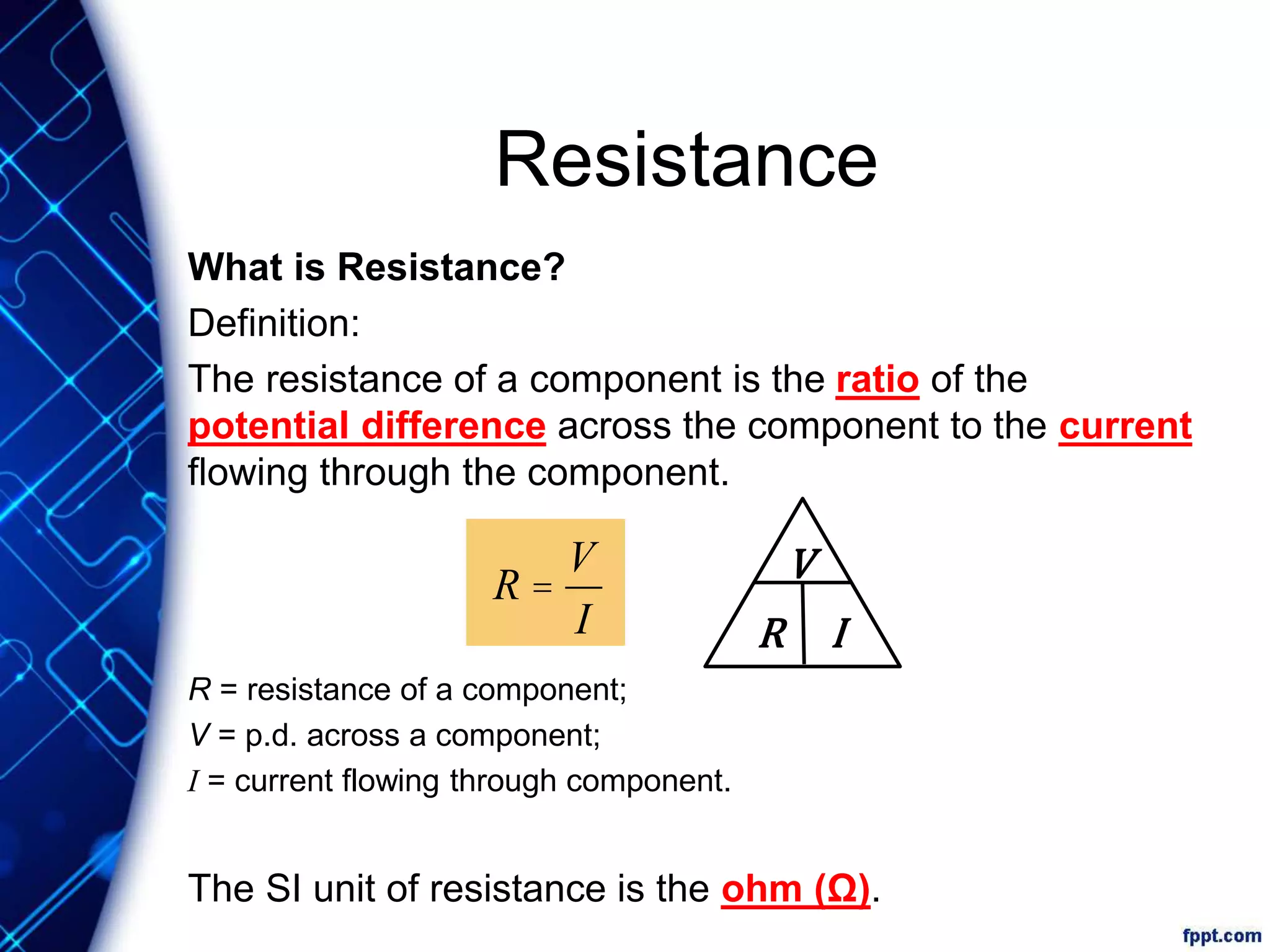
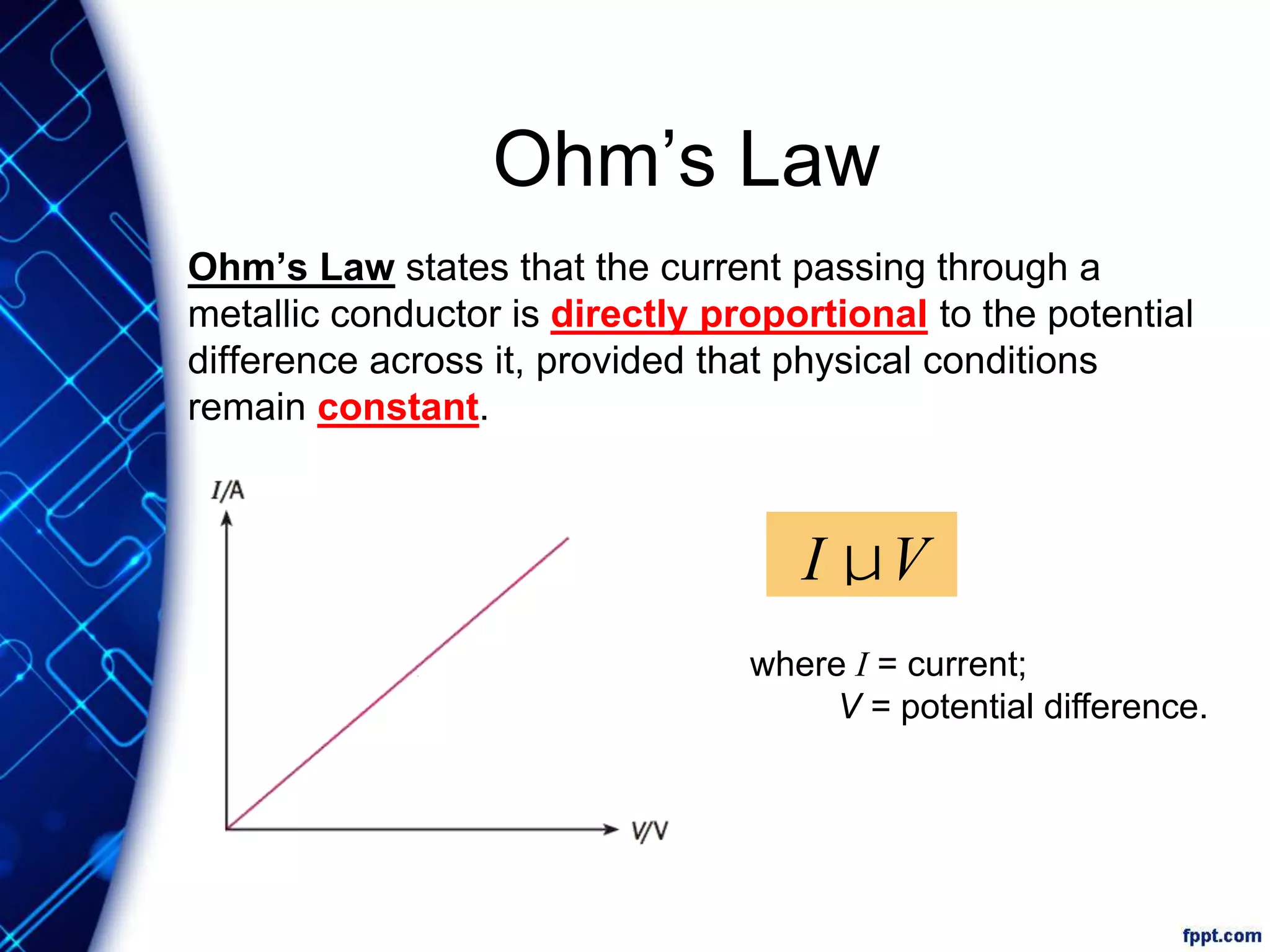
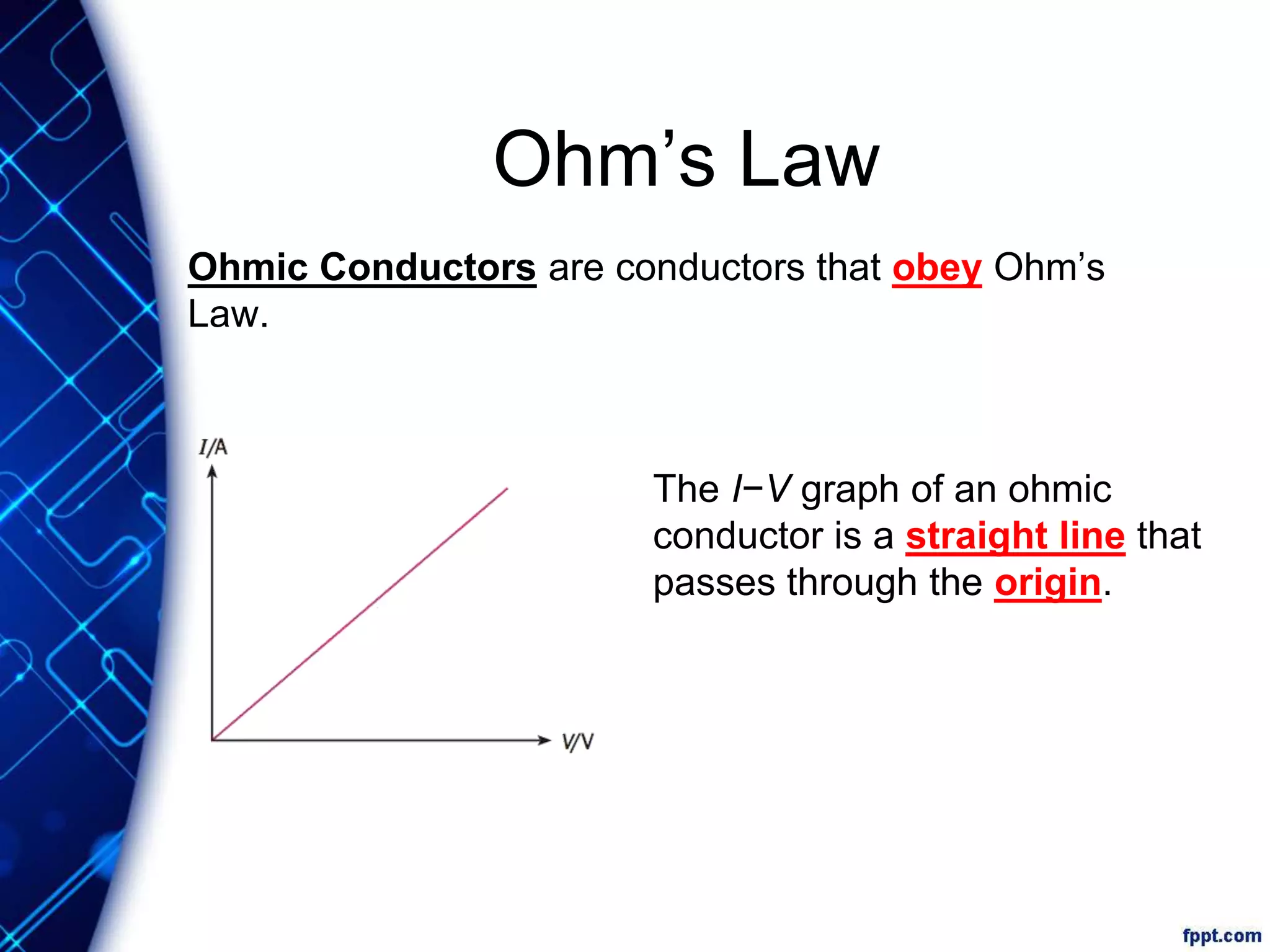
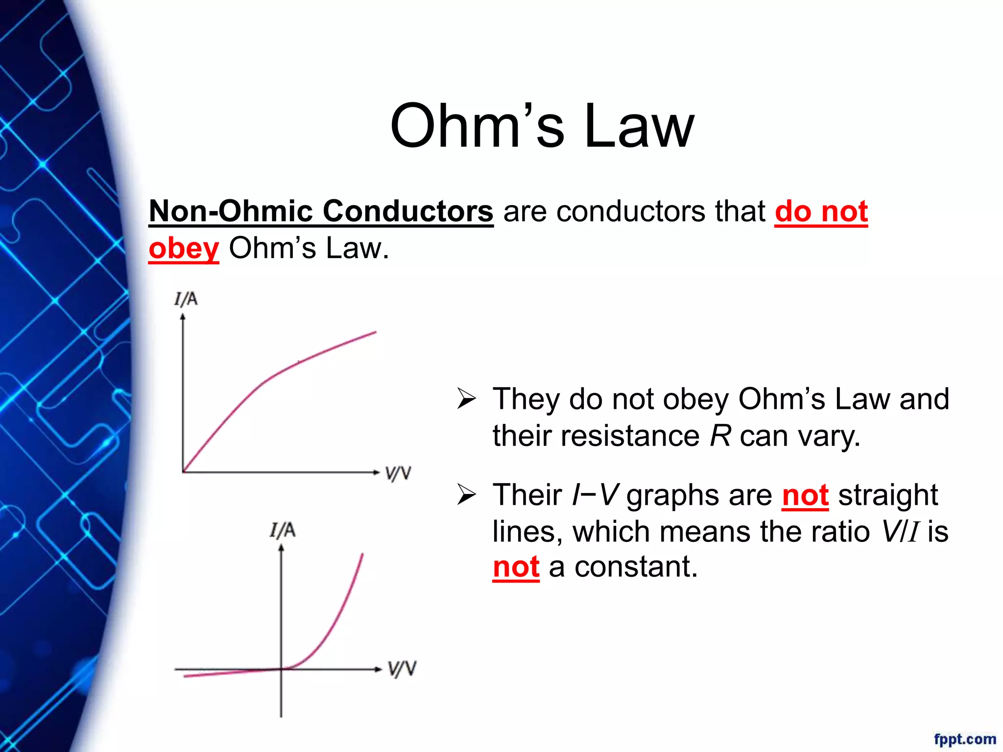
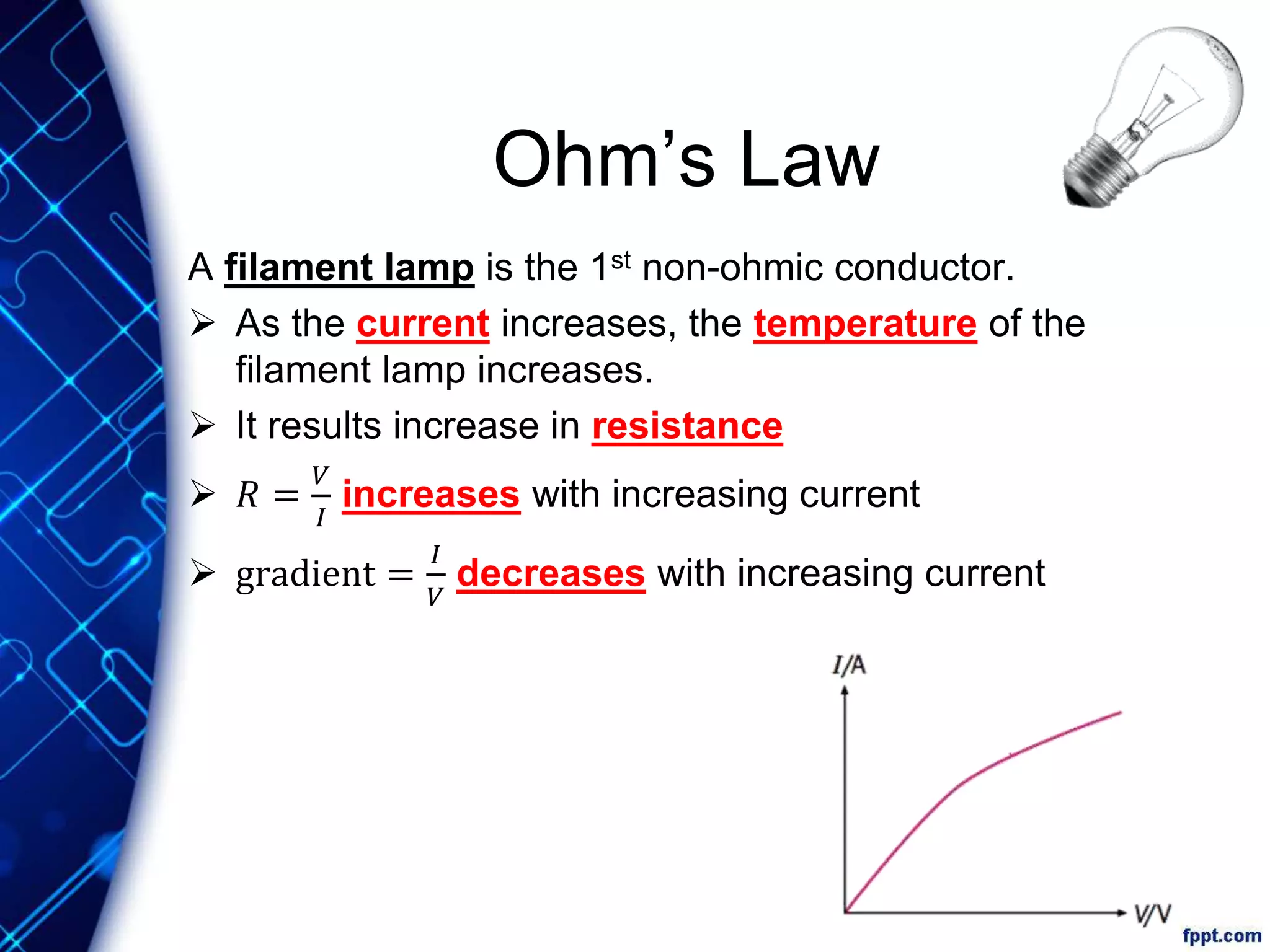
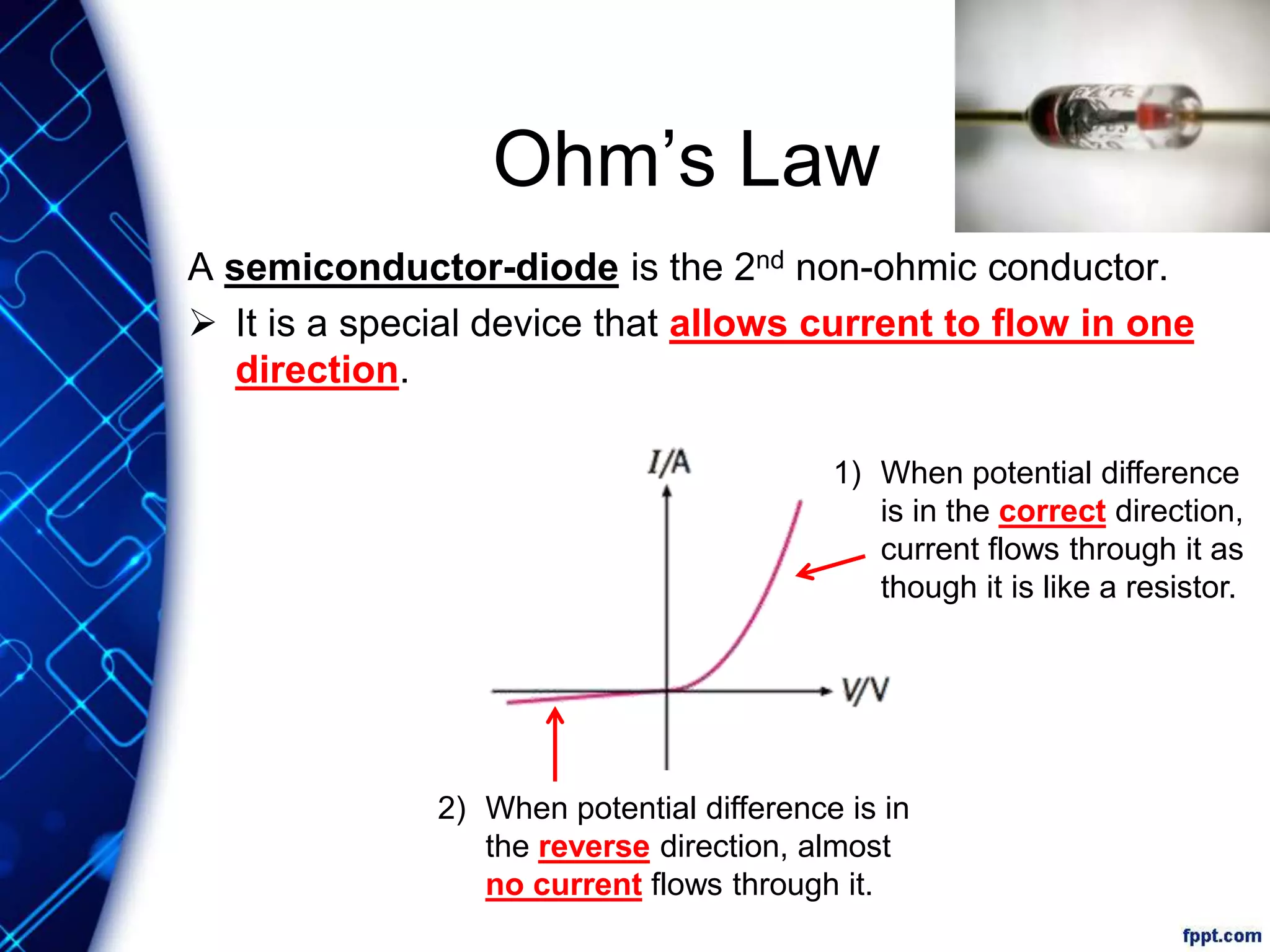
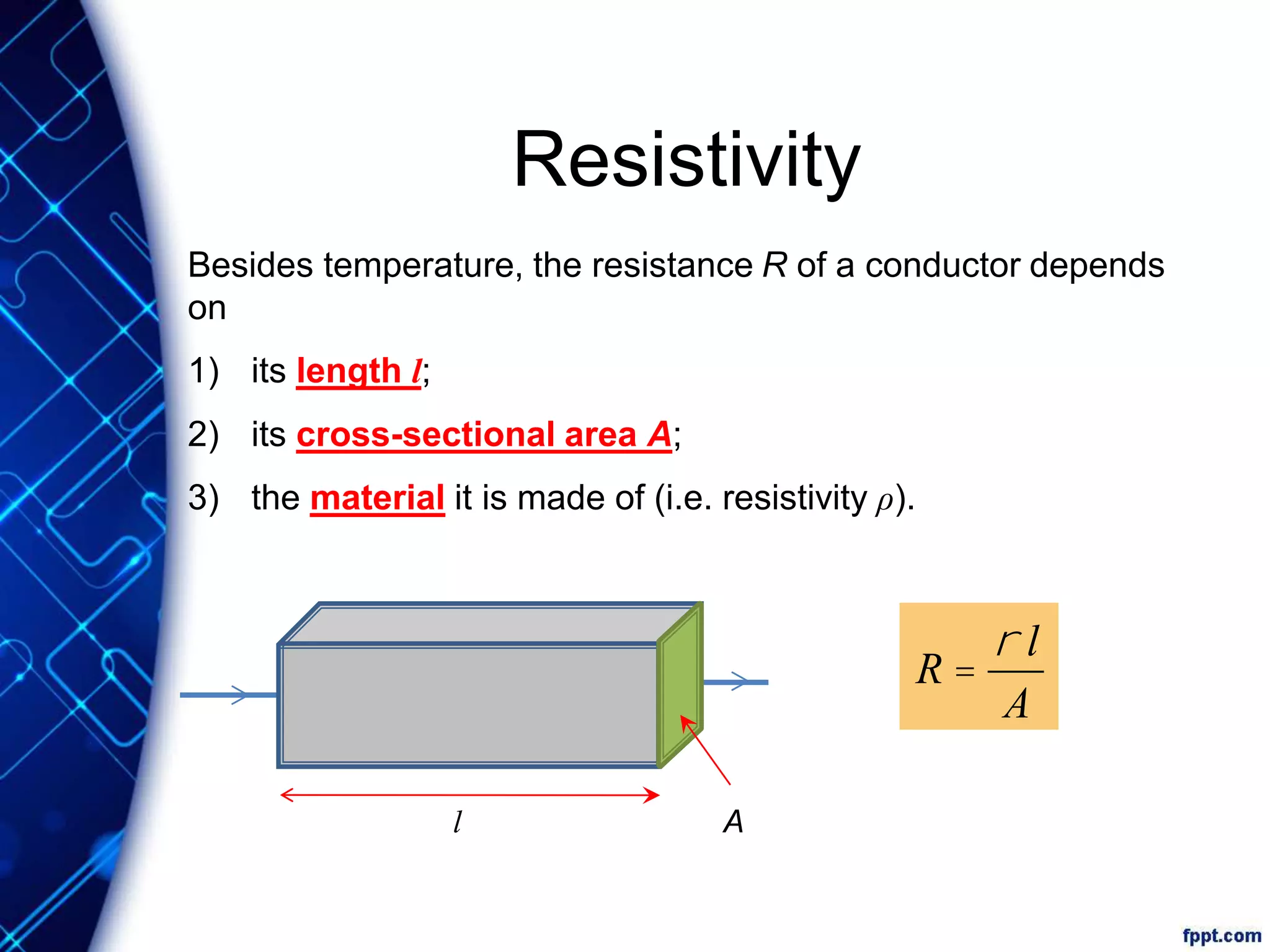
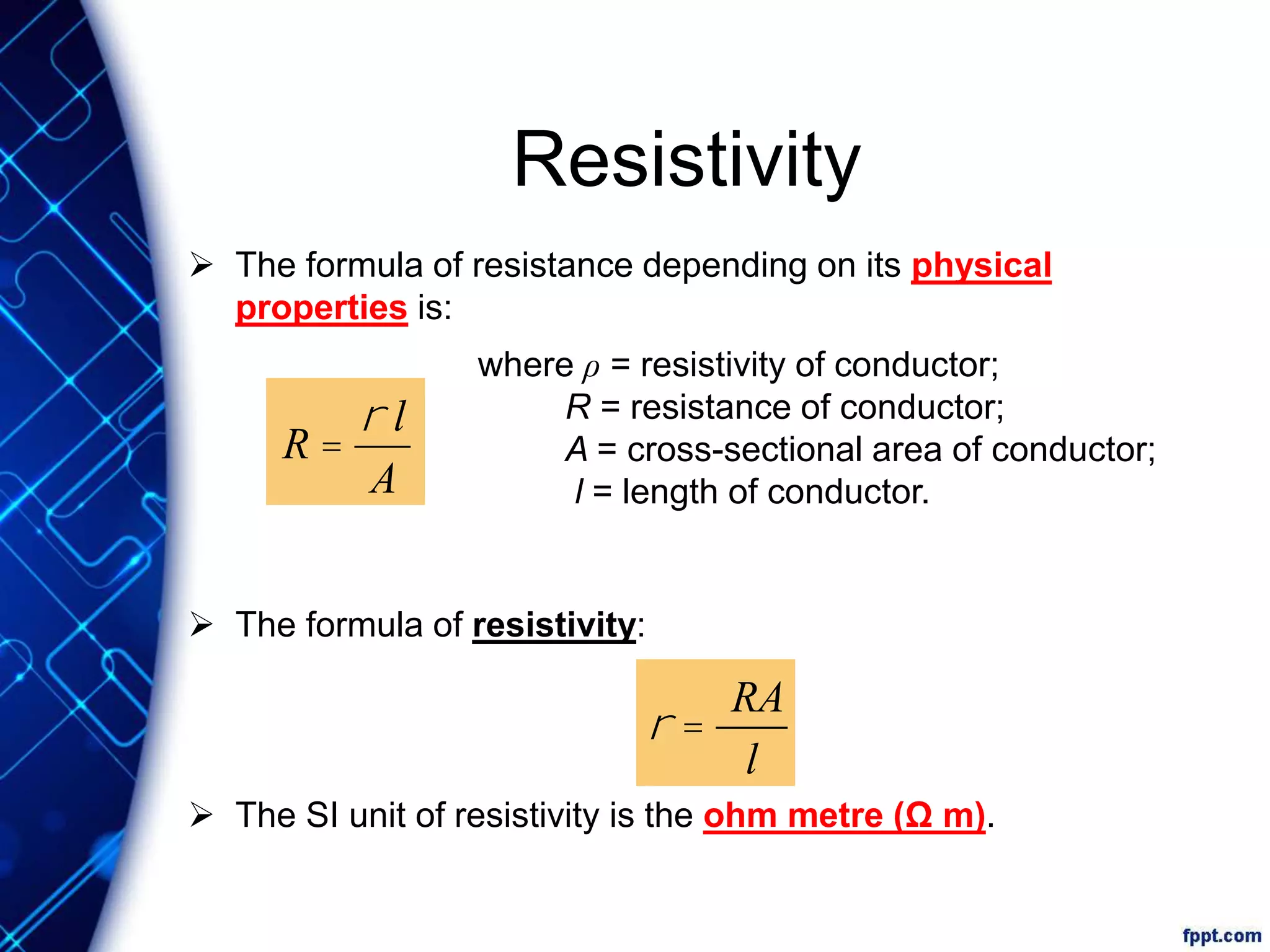
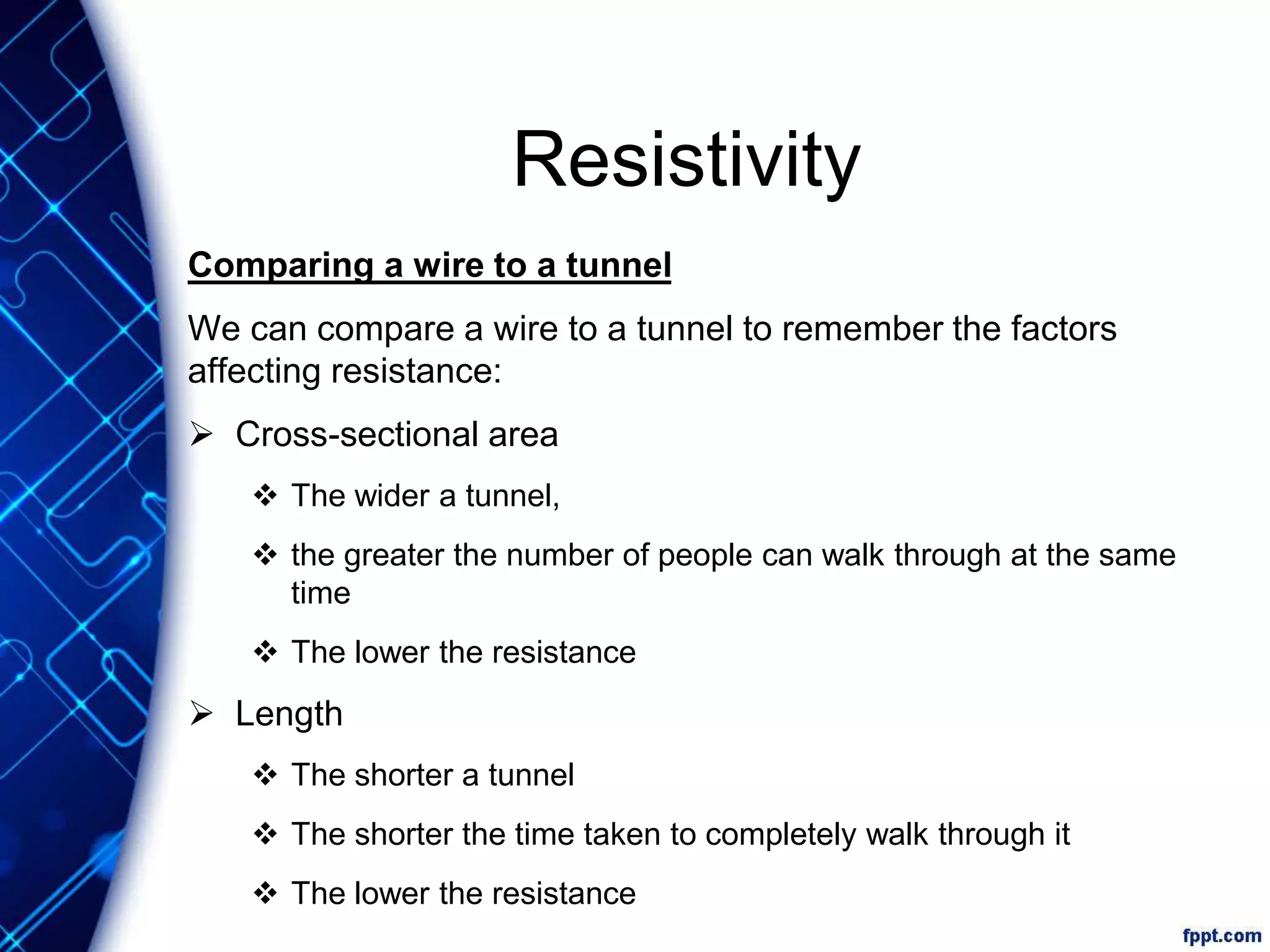
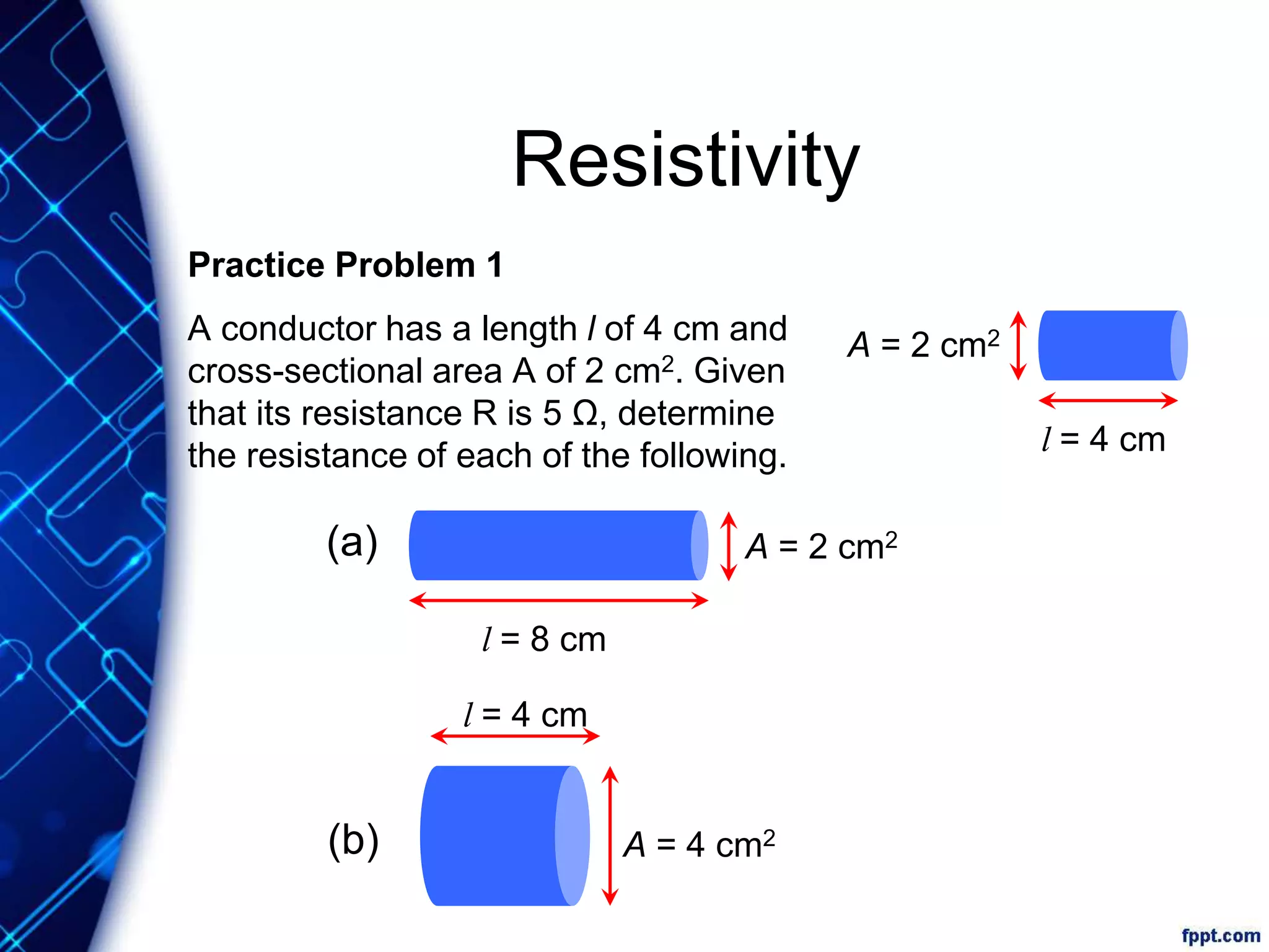
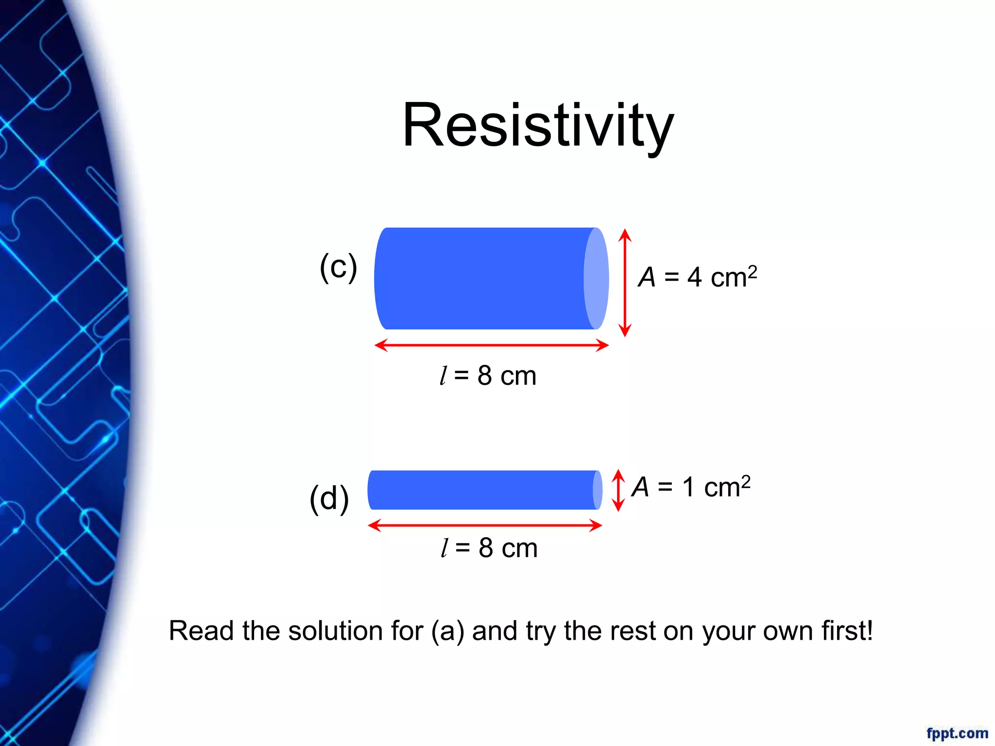
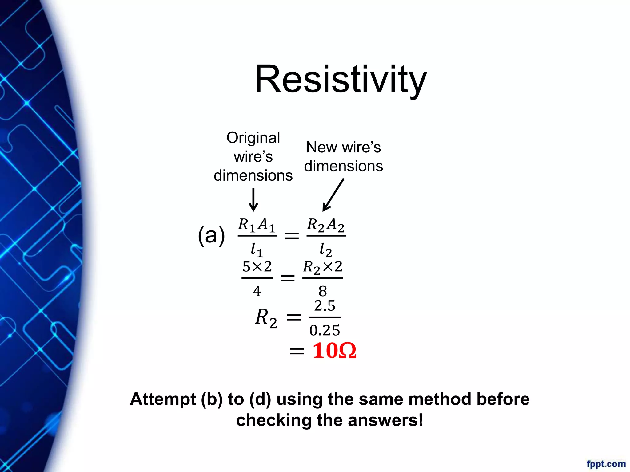
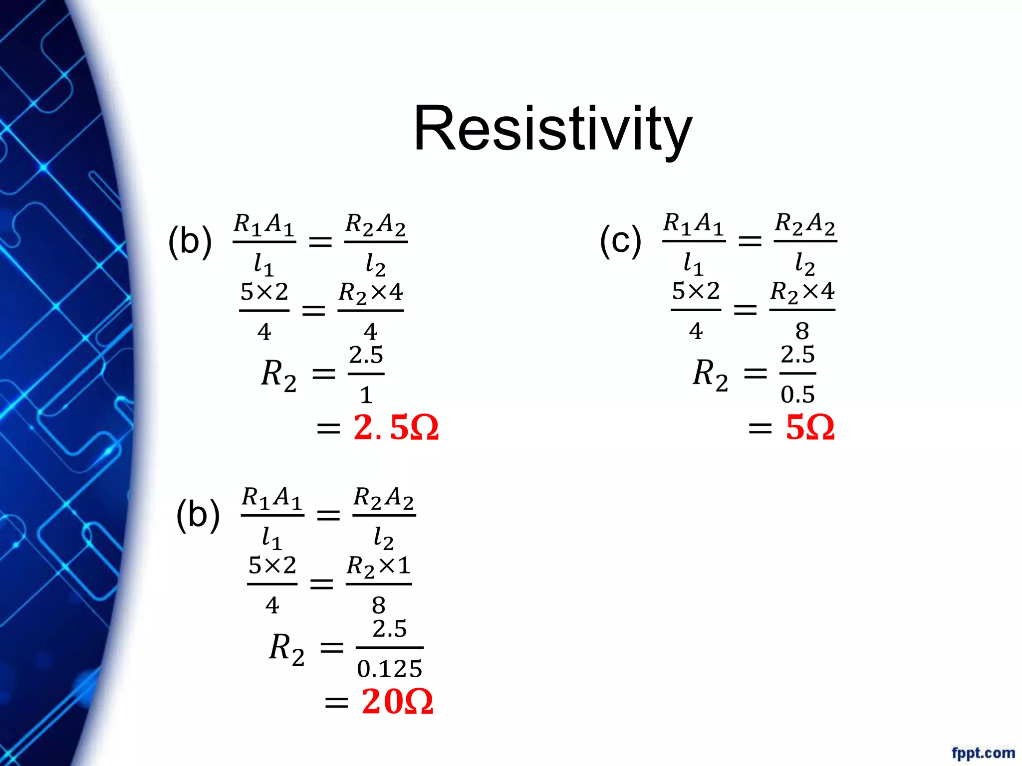
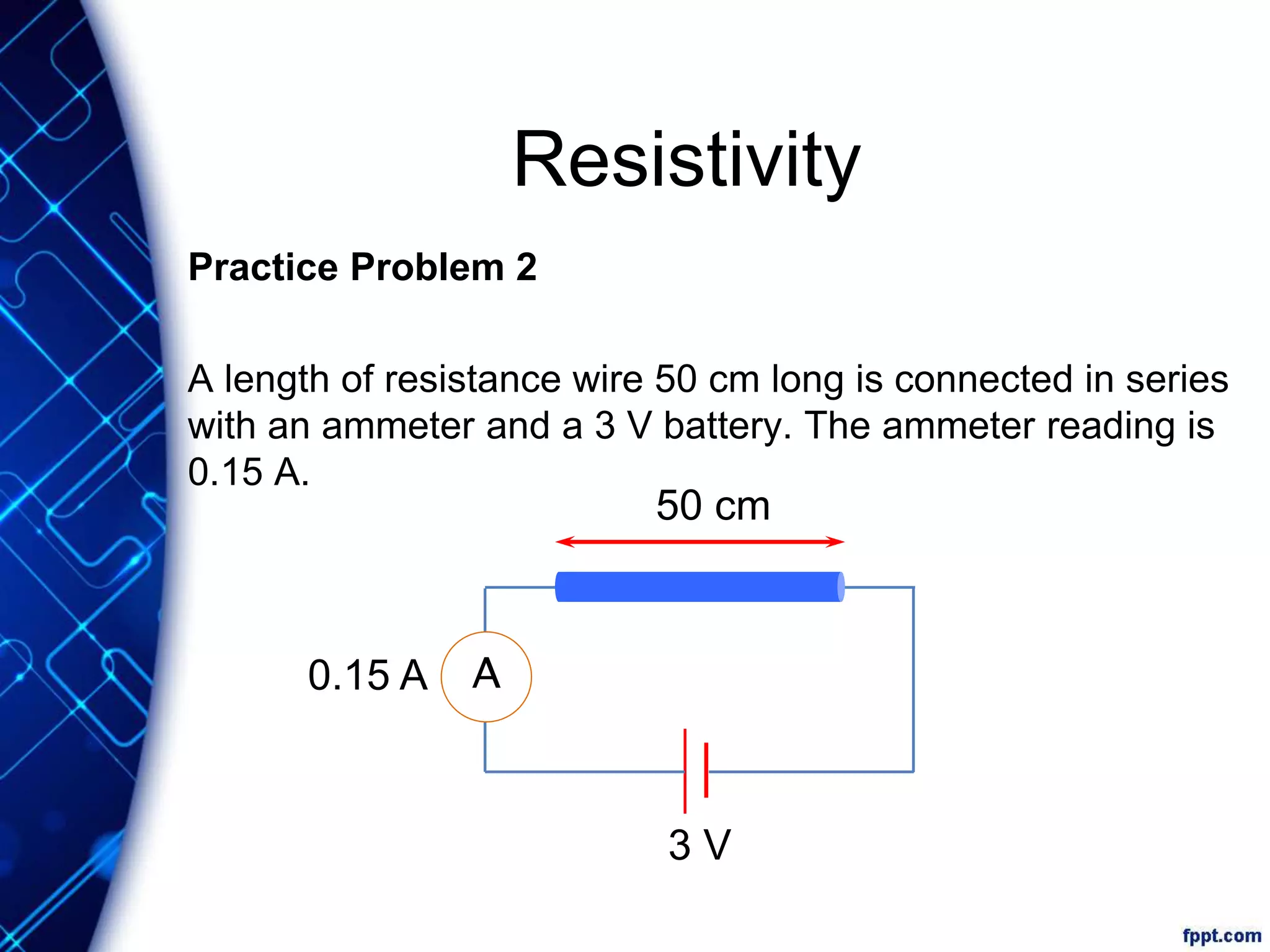
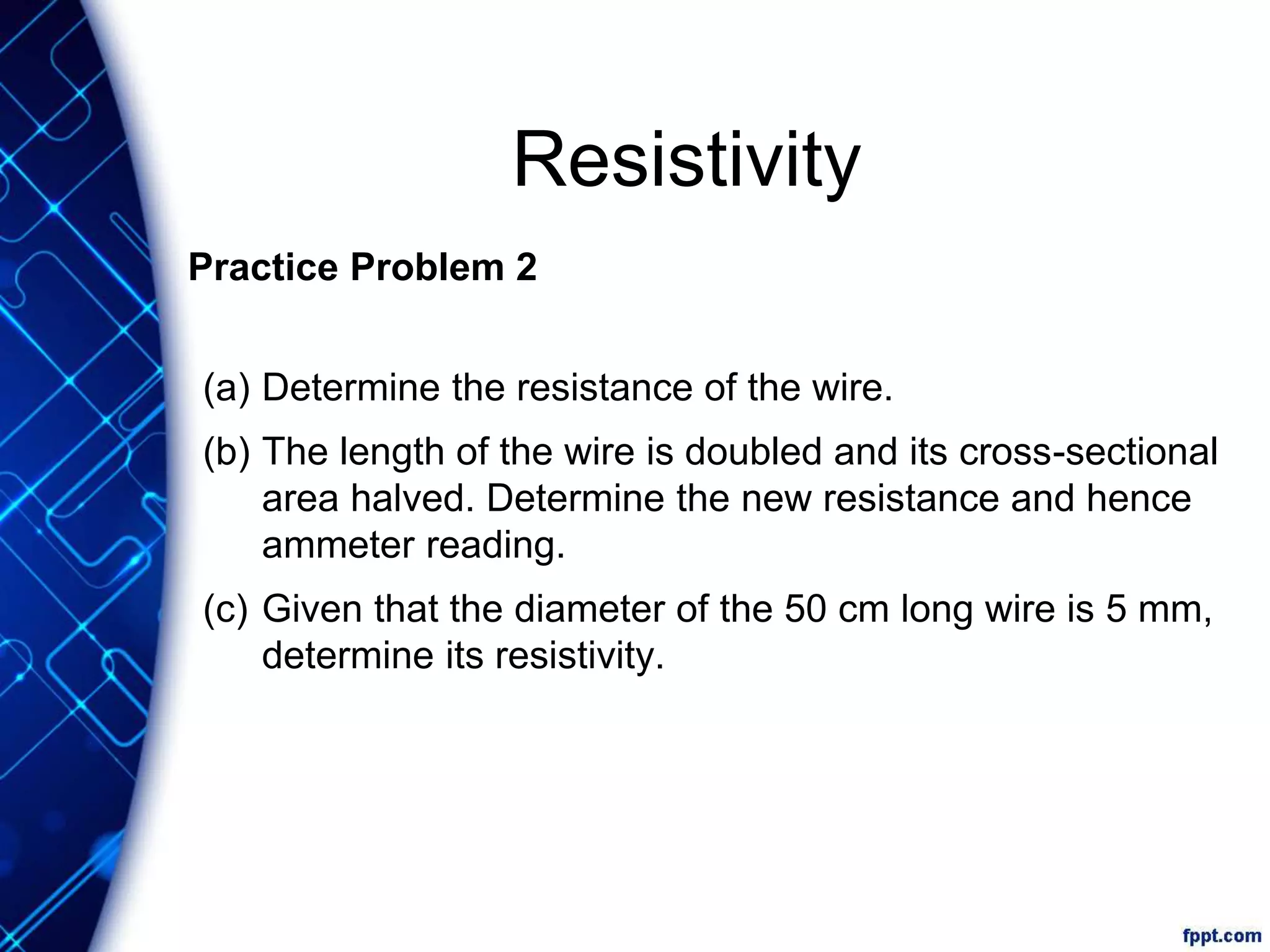
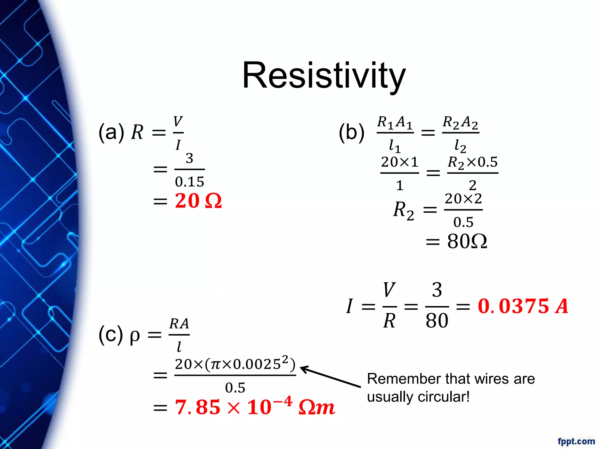
Current of Electricity
Learning Objectives
a) State that current is a rate of flow of charge and
that it is measured in amperes
b) Distinguish between conventional current and
electron flow
c) Recall and apply the relationship charge = current
× time to new situations or to solve related
problems
Electric Current
What is Electric Current?
 An electric current is formed by moving charges.
Definition:
An electric current is a measure of the rate of flow of
electric charge through a given cross-section of a
conductor.
The SI unit of electric current is the ampere (A).
I =
Q
t
where I = current;
Q = charge;
t = time taken.
Q
I t
Electric Current
Practice Problem
In one minute, 60 μC of charge passes through a point in
a circuit. Calculate the current.
Solution
I =
=
= 1 × 10⁻⁶ A
= 1 μA
Q
t
60 × 10−6 C
60 s
Electric Current
How do we measure current?
 We make use of an ammeter to measure current.
 The ammeter should be connected in series to the
circuit.
 Current must flow into positive (+)
terminal and leave negative (–)
terminal
Current inCurrent out
Electric Current
Conventional Current & Electron Flow
 Before the discovery of electrons,
scientists believed that electric current
was caused by the movement of
positive charges.
 Although this idea was later proven
wrong, the idea remains.
Conventional Current Flow Electron Flow
Movement of positive charges
From positive end of battery to
negative end of battery
Movement of electrons (–)
From negative end of battery to
positive end of battery
Electric Circuit
Main components of a circuit
 A typical electric circuit consists of four main
components.
A source of electromotive force
that drives electric charges around
the circuit.
A load in which moving charges
can do a useful job.
Conductors that connect the
components together.
A method of opening or closing the
circuit.
Dry cell
Wires
Switch
Bulb
Electric Circuit
Drawing Circuit Diagrams
 Electric circuits can be represented by circuit diagrams.
 Can you identify what the symbols in the circuit diagram
below represent?
ammeter
bulb
connecting wires
switch
cell
Electric Circuit
Drawing Circuit Diagrams
 Some common components and their symbols are
listed in the tables below.
Symbol Device
switch
cell
battery
d.c. power
supply
a.c. power
supply
light bulb
Symbol Device
wires
joined
wires
crossed
fixed
resistor
Variable resistor
(rheostat)
fuse
coil of wire
Symbol Device
galvanometer
ammeter
voltmeter
two-way
switch
earth
connector
capacitor
Electric Circuit
Interpreting Circuit Diagrams
 Open circuit
A circuit in which current is unable to flow through due
to breaks in the circuit.
Electric Circuit
Interpreting Circuit Diagrams
 Short circuit
An alternative path of lower resistance is present
and hence, current flows through wire X instead of the
bulb.
Learning Objectives
d) Define electromotive force (e.m.f.) as the work
done by a source in driving a unit charge around a
complete circuit
e) calculate the total e.m.f. where several sources
are arranged in series
f) State that the e.m.f. of a source and the potential
difference (p.d.) across a circuit component is
measured in volts
g) Define the p.d. across a component in a circuit as
the work done to drive a unit charge through the
component
Electromotive Force &
Potential Difference
What is the role of the battery in the
circuit?
Why do you need a battery to make the bulb
light up?
We can compare flow of charges to flow of water.
Electromotive Force &
Potential Difference
Flow of water in a pipe Flow of charge in a wire
The water in a horizontal pipe will
not flow unless there is a
difference in pressure between X
and Y.
The free electrons in a wire will
not flow unless they are forced to
do so.
Electromotive Force &
Potential Difference
Flow of water in a pipe Flow of charge in a wire
A pressure difference across X and
Y is required such that X is at a
higher pressure than Y
A source of energy is needed to
drive the charge round a circuit. It
may be a cell, a battery or a
generator
Water pump does work to drive
the water around the pipe.
Battery does work to drive
electrons around the circuit.
Electromotive Force &
Potential Difference
What is Electromotive Force?
Definition:
The electromotive force (e.m.f) of an electrical energy
source is defined as the work done by the source in driving
a unit charge around a complete circuit.
ε = e.m.f. of electrical energy source;
W = work done (amount of non-electrical energy converted to electrical
energy);
Q = amount of charge.
The SI unit of e.m.f is the volt (V).
W
e QQ
W
e
Electromotive Force &
Potential Difference
How do we measure e.m.f.?
 We make use of a voltmeter to measure e.m.f.
 The positive and negative terminals of a voltmeter
should be connected to the positive and negative
terminals respectively of the electrical source.
Electromotive Force &
Potential Difference
Group Activity
Objective
 Measure and observe the e.m.f. of different arrangements of
dry cells.
Instructions
1. In groups, set up the circuits shown below.
2. Record the voltmeter readings.
+ −
+ −
+
−
+ −
+
−
+ −
+
−
Series Arrangement Parallel Arrangement
Electromotive Force &
Potential Difference
When cells are arranged in
parallel, the resultant e.m.f.
is equal to that of a single
cell.
When cells are arranged in
series, the resultant e.m.f. is
the sum of all the e.m.f.s
of the cells.
Electromotive Force &
Potential Difference
What is Potential Difference?
Definition:
The potential difference (p.d.) across a component in an
electric circuit is the work done to drive a unit charge
through the component.
V = p.d. across a component;
W = work done (amount of non-electrical energy converted to electrical
energy);
Q = amount of charge.
The SI unit of potential difference is the volt (V).
W
V Q
V =
W
Q
Electromotive Force &
Potential Difference
How do we measure p.d.?
 We make use of a voltmeter to measure p.d.
 The voltmeter should be connected in parallel with the
component.
Electromotive Force &
Potential Difference
Potential Differences around a simple circuit
 The cells does work by pushing the electrons through
the whole circuit. They gain electrical potential energy.
 As they flow through each component, the electrical
potential energy is converted to other forms of energy.
Total e.m.f. in a circuit is
equal to the total p.d. across
each component
Electromotive Force &
Potential Difference
Potential Differences around a simple circuit
For a single charge,
Electrical potential energy
gain in cells
=
electrical potential energy
lost in components
𝑞𝜀1 + 𝑞𝜀2 = 𝑞𝑉1 + 𝑞𝑉2 + 𝑞𝑉3
𝜀1 + 𝜀2 = 𝑉1 + 𝑉2 + 𝑉3
sum of e. m. f. of all cells = sum of p. d. across all components
Electromotive Force &
Potential Difference
Electromotive Force vs. Potential Difference
Electromotive force Potential Difference
It is the work done to drive a
unit charge through two
points.
It is the work done by the
source in driving a unit charge
around a complete circuit.
Associated with two points in
an electric circuit
Associated with an electrical
energy source (e.g. a dry
cell)
Electromotive Force &
Potential Difference
What will the voltmeter reading show?
A The e.m.f. of the electrical source (the three cells in series)
B The e.m.f. of the bulb
C The potential difference across the bulb
Learning Objectives
h) State the definition that resistance = p.d. / current
i) Apply the relationship R = V / I to new situations or to
solve related problems
j) Describe an experiment to determine the resistance of
a metallic conductor using a voltmeter and an
ammeter, and make the necessary calculations
k) recall and apply the formulae for the effective
resistance of a number of resistors in series and in
parallel to new situations or to solve related problems
Learning Objectives
l) state Ohm’s Law
m) describe the effect of temperature increase on the
resistance of a metallic conductor
n) sketch and interpret the I/V characteristic graphs for a
metallic conductor at constant temperature, for a
filament lamp and for a semiconductor diode
Resistance
Question
Predict what will happen if a porous plate (an obstacle)
is placed in the path of the water flow.
Earlier, we used the
water pump analogy to
help us understand
e.m.f.
obstacle
Resistance
 Resistance is a measure of how difficult it is for an
electric current to pass through a material.
 It is the property of the material that restricts the
movement of free electrons in the material.
Resistor
added
Rate of flow of
electric charges
reduced
resistor
Current is
reduced
Ammeter
reading will
be reduced
Resistance
What is Resistance?
Definition:
The resistance of a component is the ratio of the
potential difference across the component to the current
flowing through the component.
R = resistance of a component;
V = p.d. across a component;
I = current flowing through component.
The SI unit of resistance is the ohm (Ω).
V
R I
R =
V
I
Resistance
How do I measure resistance?
A circuit is necessary to measure resistance.
 The ammeter is connected
in series with the bulb.
 The voltmeter is connected
in parallel with the bulb.
 Use 𝑅 =
𝑉
𝐼
+
−
−+
Resistance
In the circuit shown,
 All components have resistance.
 Wires and ammeter assumed zero resistance
 current flows through without any loss of energy
 Voltmeter considered infinite resistance
 no current flows through it
Light bulb Wires VoltmeterAmmeter
R = 0 Ω R = ∞ Ω
Resistance
What are resistors?
 A resistor is a conductor in a circuit that is used to
control the size of the current flowing in a circuit.
 There are two types of resistors — fixed resistors and
variable resistors (or rheostats).
some common fixed resistors a rheostat is a type of variable resistor
Resistance
Practice Problem
A 3 V source is connected to a light bulb,
as shown in the diagram.
The ammeter registers a reading of 0.2 A.
a) State the reading on the voltmeter.
b) Determine the resistance of the light bulb.
c) The circuit is switched on for five minutes.
i. Determine the amount of charge and;
ii. energy dissipated in the bulb.
+
−
−+
Resistance
Practice Question
(a) Voltmeter reading = 3 V
(b) R =
= 15 Ω
(c) (i) Q = It
= 0.2 A × 5 × 60 s
= 60 C
(ii) E = QV
= 60 C × 3 V
= 180 J
3 V
0.2 A
Ohm’s Law
Ohm’s Law states that the current passing through a
metallic conductor is directly proportional to the potential
difference across it, provided that physical conditions
remain constant.
where I = current;
V = potential difference.
I µV
Ohm’s Law
Ohmic Conductors are conductors that obey Ohm’s
Law.
The I−V graph of an ohmic
conductor is a straight line that
passes through the origin.
Ohm’s Law
Non-Ohmic Conductors are conductors that do not
obey Ohm’s Law.
 They do not obey Ohm’s Law and
their resistance R can vary.
 Their I−V graphs are not straight
lines, which means the ratio V/I is
not a constant.
Ohm’s Law
A filament lamp is the 1st non-ohmic conductor.
 As the current increases, the temperature of the
filament lamp increases.
 It results increase in resistance
 𝑅 =
𝑉
𝐼
increases with increasing current
 gradient =
𝐼
𝑉
decreases with increasing current
Ohm’s Law
A semiconductor-diode is the 2nd non-ohmic conductor.
 It is a special device that allows current to flow in one
direction.
1) When potential difference
is in the correct direction,
current flows through it as
though it is like a resistor.
2) When potential difference is in
the reverse direction, almost
no current flows through it.
Learning Objectives
o) Recall and apply the relationship of the proportionality
between resistance and the length and cross-sectional
area of a wire to new situations or to solve related
problems
Resistivity
Besides temperature, the resistance R of a conductor depends
on
1) its length l;
2) its cross-sectional area A;
3) the material it is made of (i.e. resistivity ρ).
l A
R =
r l
A
Resistivity
 The formula of resistance depending on its physical
properties is:
 The formula of resistivity:
 The SI unit of resistivity is the ohm metre (Ω m).
R =
r l
A
where ρ = resistivity of conductor;
R = resistance of conductor;
A = cross-sectional area of conductor;
l = length of conductor.
r =
RA
l
Resistivity
 Different materials have
different resistivities.
 Resistivity is a property of
the material and it is
independent of the
dimensions of the material.
 The lower the resistivity of a
material, the better it is at
conducting electricity.
Resistivity
Comparing a wire to a tunnel
We can compare a wire to a tunnel to remember the factors
affecting resistance:
 Cross-sectional area
 The wider a tunnel,
 the greater the number of people can walk through at the same
time
 The lower the resistance
 Length
 The shorter a tunnel
 The shorter the time taken to completely walk through it
 The lower the resistance
Resistivity
Tackling problems
Resistivity questions generally look like this:
1) I have a wire with resistance R1, length l1 and area A1.
2) If I use the same material but new length l2 and area A2, find
its new resistance R2.
Since it is the same material, its resistivity r must be constant.
Therefore
𝑹 𝟏 𝑨 𝟏
𝒍 𝟏
= 𝝆 =
𝑹 𝟐 𝑨 𝟐
𝒍 𝟐Original
wire’s
dimensions
New wire’s
dimensions
Resistivity
Practice Problem 1
A conductor has a length l of 4 cm and
cross-sectional area A of 2 cm2. Given
that its resistance R is 5 Ω, determine
the resistance of each of the following. l = 4 cm
A = 2 cm2
l = 4 cm
A = 4 cm2
l = 8 cm
A = 2 cm2(a)
(b)
Resistivity
l = 8 cm
A = 4 cm2(c)
l = 8 cm
A = 1 cm2
(d)
Read the solution for (a) and try the rest on your own first!
Resistivity
(a)
𝑅1 𝐴1
𝑙1
=
𝑅2 𝐴2
𝑙2
5×2
4
=
𝑅2×2
8
𝑅2 =
2.5
0.25
= 𝟏𝟎W
Original
wire’s
dimensions
New wire’s
dimensions
Attempt (b) to (d) using the same method before
checking the answers!
Resistivity
(c)
𝑅1 𝐴1
𝑙1
=
𝑅2 𝐴2
𝑙2
5×2
4
=
𝑅2×4
8
𝑅2 =
2.5
0.5
= 𝟓W
(b)
𝑅1 𝐴1
𝑙1
=
𝑅2 𝐴2
𝑙2
5×2
4
=
𝑅2×1
8
𝑅2 =
2.5
0.125
= 𝟐𝟎W
(b)
𝑅1 𝐴1
𝑙1
=
𝑅2 𝐴2
𝑙2
5×2
4
=
𝑅2×4
4
𝑅2 =
2.5
1
= 𝟐. 𝟓W
Resistivity
Practice Problem 2
A length of resistance wire 50 cm long is connected in series
with an ammeter and a 3 V battery. The ammeter reading is
0.15 A.
A
50 cm
3 V
0.15 A
Resistivity
Practice Problem 2
(a) Determine the resistance of the wire.
(b) The length of the wire is doubled and its cross-sectional
area halved. Determine the new resistance and hence
ammeter reading.
(c) Given that the diameter of the 50 cm long wire is 5 mm,
determine its resistivity.
Resistivity
(a) 𝑅 =
𝑉
𝐼
=
3
0.15
= 𝟐𝟎 W
(b)
𝑅1 𝐴1
𝑙1
=
𝑅2 𝐴2
𝑙2
20×1
1
=
𝑅2×0.5
2
𝑅2 =
20×2
0.5
= 80W
𝐼 =
𝑉
𝑅
=
3
80
= 𝟎. 𝟎𝟑𝟕𝟓 𝑨
(c) ρ =
𝑅𝐴
𝑙
=
20×(𝜋×0.00252)
0.5
= 𝟕. 𝟖𝟓 × 𝟏𝟎−𝟒
W𝒎
Remember that wires are
usually circular!

Exp SPA - Chp 17 Current of Electricity

  • 1.
  • 2.
    Learning Objectives a) Statethat current is a rate of flow of charge and that it is measured in amperes b) Distinguish between conventional current and electron flow c) Recall and apply the relationship charge = current × time to new situations or to solve related problems
  • 3.
    Electric Current What isElectric Current?  An electric current is formed by moving charges. Definition: An electric current is a measure of the rate of flow of electric charge through a given cross-section of a conductor. The SI unit of electric current is the ampere (A). I = Q t where I = current; Q = charge; t = time taken. Q I t
  • 4.
    Electric Current Practice Problem Inone minute, 60 μC of charge passes through a point in a circuit. Calculate the current. Solution I = = = 1 × 10⁻⁶ A = 1 μA Q t 60 × 10−6 C 60 s
  • 5.
    Electric Current How dowe measure current?  We make use of an ammeter to measure current.  The ammeter should be connected in series to the circuit.  Current must flow into positive (+) terminal and leave negative (–) terminal Current inCurrent out
  • 6.
    Electric Current Conventional Current& Electron Flow  Before the discovery of electrons, scientists believed that electric current was caused by the movement of positive charges.  Although this idea was later proven wrong, the idea remains. Conventional Current Flow Electron Flow Movement of positive charges From positive end of battery to negative end of battery Movement of electrons (–) From negative end of battery to positive end of battery
  • 7.
    Electric Circuit Main componentsof a circuit  A typical electric circuit consists of four main components. A source of electromotive force that drives electric charges around the circuit. A load in which moving charges can do a useful job. Conductors that connect the components together. A method of opening or closing the circuit. Dry cell Wires Switch Bulb
  • 8.
    Electric Circuit Drawing CircuitDiagrams  Electric circuits can be represented by circuit diagrams.  Can you identify what the symbols in the circuit diagram below represent? ammeter bulb connecting wires switch cell
  • 9.
    Electric Circuit Drawing CircuitDiagrams  Some common components and their symbols are listed in the tables below. Symbol Device switch cell battery d.c. power supply a.c. power supply light bulb Symbol Device wires joined wires crossed fixed resistor Variable resistor (rheostat) fuse coil of wire Symbol Device galvanometer ammeter voltmeter two-way switch earth connector capacitor
  • 10.
    Electric Circuit Interpreting CircuitDiagrams  Open circuit A circuit in which current is unable to flow through due to breaks in the circuit.
  • 11.
    Electric Circuit Interpreting CircuitDiagrams  Short circuit An alternative path of lower resistance is present and hence, current flows through wire X instead of the bulb.
  • 12.
    Learning Objectives d) Defineelectromotive force (e.m.f.) as the work done by a source in driving a unit charge around a complete circuit e) calculate the total e.m.f. where several sources are arranged in series f) State that the e.m.f. of a source and the potential difference (p.d.) across a circuit component is measured in volts g) Define the p.d. across a component in a circuit as the work done to drive a unit charge through the component
  • 13.
    Electromotive Force & PotentialDifference What is the role of the battery in the circuit? Why do you need a battery to make the bulb light up?
  • 14.
    We can compareflow of charges to flow of water. Electromotive Force & Potential Difference Flow of water in a pipe Flow of charge in a wire The water in a horizontal pipe will not flow unless there is a difference in pressure between X and Y. The free electrons in a wire will not flow unless they are forced to do so.
  • 15.
    Electromotive Force & PotentialDifference Flow of water in a pipe Flow of charge in a wire A pressure difference across X and Y is required such that X is at a higher pressure than Y A source of energy is needed to drive the charge round a circuit. It may be a cell, a battery or a generator Water pump does work to drive the water around the pipe. Battery does work to drive electrons around the circuit.
  • 16.
    Electromotive Force & PotentialDifference What is Electromotive Force? Definition: The electromotive force (e.m.f) of an electrical energy source is defined as the work done by the source in driving a unit charge around a complete circuit. ε = e.m.f. of electrical energy source; W = work done (amount of non-electrical energy converted to electrical energy); Q = amount of charge. The SI unit of e.m.f is the volt (V). W e QQ W e
  • 17.
    Electromotive Force & PotentialDifference How do we measure e.m.f.?  We make use of a voltmeter to measure e.m.f.  The positive and negative terminals of a voltmeter should be connected to the positive and negative terminals respectively of the electrical source.
  • 18.
    Electromotive Force & PotentialDifference Group Activity Objective  Measure and observe the e.m.f. of different arrangements of dry cells. Instructions 1. In groups, set up the circuits shown below. 2. Record the voltmeter readings. + − + − + − + − + − + − + −
  • 19.
    Series Arrangement ParallelArrangement Electromotive Force & Potential Difference When cells are arranged in parallel, the resultant e.m.f. is equal to that of a single cell. When cells are arranged in series, the resultant e.m.f. is the sum of all the e.m.f.s of the cells.
  • 20.
    Electromotive Force & PotentialDifference What is Potential Difference? Definition: The potential difference (p.d.) across a component in an electric circuit is the work done to drive a unit charge through the component. V = p.d. across a component; W = work done (amount of non-electrical energy converted to electrical energy); Q = amount of charge. The SI unit of potential difference is the volt (V). W V Q V = W Q
  • 21.
    Electromotive Force & PotentialDifference How do we measure p.d.?  We make use of a voltmeter to measure p.d.  The voltmeter should be connected in parallel with the component.
  • 22.
    Electromotive Force & PotentialDifference Potential Differences around a simple circuit  The cells does work by pushing the electrons through the whole circuit. They gain electrical potential energy.  As they flow through each component, the electrical potential energy is converted to other forms of energy. Total e.m.f. in a circuit is equal to the total p.d. across each component
  • 23.
    Electromotive Force & PotentialDifference Potential Differences around a simple circuit For a single charge, Electrical potential energy gain in cells = electrical potential energy lost in components 𝑞𝜀1 + 𝑞𝜀2 = 𝑞𝑉1 + 𝑞𝑉2 + 𝑞𝑉3 𝜀1 + 𝜀2 = 𝑉1 + 𝑉2 + 𝑉3 sum of e. m. f. of all cells = sum of p. d. across all components
  • 24.
    Electromotive Force & PotentialDifference Electromotive Force vs. Potential Difference Electromotive force Potential Difference It is the work done to drive a unit charge through two points. It is the work done by the source in driving a unit charge around a complete circuit. Associated with two points in an electric circuit Associated with an electrical energy source (e.g. a dry cell)
  • 25.
    Electromotive Force & PotentialDifference What will the voltmeter reading show? A The e.m.f. of the electrical source (the three cells in series) B The e.m.f. of the bulb C The potential difference across the bulb
  • 26.
    Learning Objectives h) Statethe definition that resistance = p.d. / current i) Apply the relationship R = V / I to new situations or to solve related problems j) Describe an experiment to determine the resistance of a metallic conductor using a voltmeter and an ammeter, and make the necessary calculations k) recall and apply the formulae for the effective resistance of a number of resistors in series and in parallel to new situations or to solve related problems
  • 27.
    Learning Objectives l) stateOhm’s Law m) describe the effect of temperature increase on the resistance of a metallic conductor n) sketch and interpret the I/V characteristic graphs for a metallic conductor at constant temperature, for a filament lamp and for a semiconductor diode
  • 28.
    Resistance Question Predict what willhappen if a porous plate (an obstacle) is placed in the path of the water flow. Earlier, we used the water pump analogy to help us understand e.m.f. obstacle
  • 29.
    Resistance  Resistance isa measure of how difficult it is for an electric current to pass through a material.  It is the property of the material that restricts the movement of free electrons in the material. Resistor added Rate of flow of electric charges reduced resistor Current is reduced Ammeter reading will be reduced
  • 30.
    Resistance What is Resistance? Definition: Theresistance of a component is the ratio of the potential difference across the component to the current flowing through the component. R = resistance of a component; V = p.d. across a component; I = current flowing through component. The SI unit of resistance is the ohm (Ω). V R I R = V I
  • 31.
    Resistance How do Imeasure resistance? A circuit is necessary to measure resistance.  The ammeter is connected in series with the bulb.  The voltmeter is connected in parallel with the bulb.  Use 𝑅 = 𝑉 𝐼 + − −+
  • 32.
    Resistance In the circuitshown,  All components have resistance.  Wires and ammeter assumed zero resistance  current flows through without any loss of energy  Voltmeter considered infinite resistance  no current flows through it Light bulb Wires VoltmeterAmmeter R = 0 Ω R = ∞ Ω
  • 33.
    Resistance What are resistors? A resistor is a conductor in a circuit that is used to control the size of the current flowing in a circuit.  There are two types of resistors — fixed resistors and variable resistors (or rheostats). some common fixed resistors a rheostat is a type of variable resistor
  • 34.
    Resistance Practice Problem A 3V source is connected to a light bulb, as shown in the diagram. The ammeter registers a reading of 0.2 A. a) State the reading on the voltmeter. b) Determine the resistance of the light bulb. c) The circuit is switched on for five minutes. i. Determine the amount of charge and; ii. energy dissipated in the bulb. + − −+
  • 35.
    Resistance Practice Question (a) Voltmeterreading = 3 V (b) R = = 15 Ω (c) (i) Q = It = 0.2 A × 5 × 60 s = 60 C (ii) E = QV = 60 C × 3 V = 180 J 3 V 0.2 A
  • 36.
    Ohm’s Law Ohm’s Lawstates that the current passing through a metallic conductor is directly proportional to the potential difference across it, provided that physical conditions remain constant. where I = current; V = potential difference. I µV
  • 37.
    Ohm’s Law Ohmic Conductorsare conductors that obey Ohm’s Law. The I−V graph of an ohmic conductor is a straight line that passes through the origin.
  • 38.
    Ohm’s Law Non-Ohmic Conductorsare conductors that do not obey Ohm’s Law.  They do not obey Ohm’s Law and their resistance R can vary.  Their I−V graphs are not straight lines, which means the ratio V/I is not a constant.
  • 39.
    Ohm’s Law A filamentlamp is the 1st non-ohmic conductor.  As the current increases, the temperature of the filament lamp increases.  It results increase in resistance  𝑅 = 𝑉 𝐼 increases with increasing current  gradient = 𝐼 𝑉 decreases with increasing current
  • 40.
    Ohm’s Law A semiconductor-diodeis the 2nd non-ohmic conductor.  It is a special device that allows current to flow in one direction. 1) When potential difference is in the correct direction, current flows through it as though it is like a resistor. 2) When potential difference is in the reverse direction, almost no current flows through it.
  • 41.
    Learning Objectives o) Recalland apply the relationship of the proportionality between resistance and the length and cross-sectional area of a wire to new situations or to solve related problems
  • 42.
    Resistivity Besides temperature, theresistance R of a conductor depends on 1) its length l; 2) its cross-sectional area A; 3) the material it is made of (i.e. resistivity ρ). l A R = r l A
  • 43.
    Resistivity  The formulaof resistance depending on its physical properties is:  The formula of resistivity:  The SI unit of resistivity is the ohm metre (Ω m). R = r l A where ρ = resistivity of conductor; R = resistance of conductor; A = cross-sectional area of conductor; l = length of conductor. r = RA l
  • 44.
    Resistivity  Different materialshave different resistivities.  Resistivity is a property of the material and it is independent of the dimensions of the material.  The lower the resistivity of a material, the better it is at conducting electricity.
  • 45.
    Resistivity Comparing a wireto a tunnel We can compare a wire to a tunnel to remember the factors affecting resistance:  Cross-sectional area  The wider a tunnel,  the greater the number of people can walk through at the same time  The lower the resistance  Length  The shorter a tunnel  The shorter the time taken to completely walk through it  The lower the resistance
  • 46.
    Resistivity Tackling problems Resistivity questionsgenerally look like this: 1) I have a wire with resistance R1, length l1 and area A1. 2) If I use the same material but new length l2 and area A2, find its new resistance R2. Since it is the same material, its resistivity r must be constant. Therefore 𝑹 𝟏 𝑨 𝟏 𝒍 𝟏 = 𝝆 = 𝑹 𝟐 𝑨 𝟐 𝒍 𝟐Original wire’s dimensions New wire’s dimensions
  • 47.
    Resistivity Practice Problem 1 Aconductor has a length l of 4 cm and cross-sectional area A of 2 cm2. Given that its resistance R is 5 Ω, determine the resistance of each of the following. l = 4 cm A = 2 cm2 l = 4 cm A = 4 cm2 l = 8 cm A = 2 cm2(a) (b)
  • 48.
    Resistivity l = 8cm A = 4 cm2(c) l = 8 cm A = 1 cm2 (d) Read the solution for (a) and try the rest on your own first!
  • 49.
    Resistivity (a) 𝑅1 𝐴1 𝑙1 = 𝑅2 𝐴2 𝑙2 5×2 4 = 𝑅2×2 8 𝑅2= 2.5 0.25 = 𝟏𝟎W Original wire’s dimensions New wire’s dimensions Attempt (b) to (d) using the same method before checking the answers!
  • 50.
    Resistivity (c) 𝑅1 𝐴1 𝑙1 = 𝑅2 𝐴2 𝑙2 5×2 4 = 𝑅2×4 8 𝑅2= 2.5 0.5 = 𝟓W (b) 𝑅1 𝐴1 𝑙1 = 𝑅2 𝐴2 𝑙2 5×2 4 = 𝑅2×1 8 𝑅2 = 2.5 0.125 = 𝟐𝟎W (b) 𝑅1 𝐴1 𝑙1 = 𝑅2 𝐴2 𝑙2 5×2 4 = 𝑅2×4 4 𝑅2 = 2.5 1 = 𝟐. 𝟓W
  • 51.
    Resistivity Practice Problem 2 Alength of resistance wire 50 cm long is connected in series with an ammeter and a 3 V battery. The ammeter reading is 0.15 A. A 50 cm 3 V 0.15 A
  • 52.
    Resistivity Practice Problem 2 (a)Determine the resistance of the wire. (b) The length of the wire is doubled and its cross-sectional area halved. Determine the new resistance and hence ammeter reading. (c) Given that the diameter of the 50 cm long wire is 5 mm, determine its resistivity.
  • 53.
    Resistivity (a) 𝑅 = 𝑉 𝐼 = 3 0.15 =𝟐𝟎 W (b) 𝑅1 𝐴1 𝑙1 = 𝑅2 𝐴2 𝑙2 20×1 1 = 𝑅2×0.5 2 𝑅2 = 20×2 0.5 = 80W 𝐼 = 𝑉 𝑅 = 3 80 = 𝟎. 𝟎𝟑𝟕𝟓 𝑨 (c) ρ = 𝑅𝐴 𝑙 = 20×(𝜋×0.00252) 0.5 = 𝟕. 𝟖𝟓 × 𝟏𝟎−𝟒 W𝒎 Remember that wires are usually circular!

Editor's Notes

  • #26 Ask students to tackle these questions in pairs, before sharing the answer with the class. Answer A and C For the circuit shown, the voltmeter measures both the e.m.f. of the battery as well as the p.d. across the bulb; the e.m.f. of the battery and the p.d. across the bulb is the same in this case. As the bulb is not an electrical source, it does not have e.m.f.