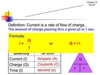
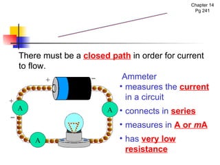
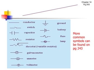
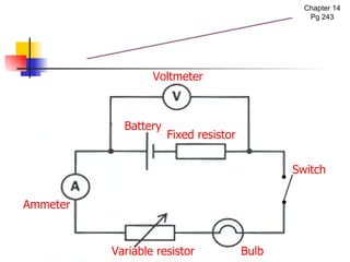
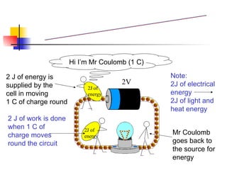
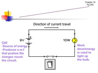
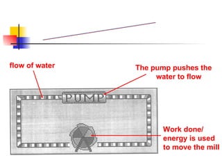
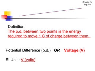
The document covers the fundamentals of electric current, including the definitions of current, electromotive force (e.m.f.), potential difference (p.d.), and resistance, along with their respective formulas and units. It provides examples demonstrating how to calculate current, charge, and resistance using various scenarios. Additionally, it explains measurement instruments like ammeters and voltmeters and their functions in electric circuits.
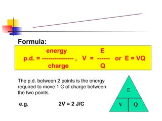
![Example 1: A current of 10 A flows through an electric heater for 10 minutes. What is the total charge circulated through the heater? [Solution] t = 10 min x 60 = 600 s I = 10 A Q = I t = 10 A x 600 s = 6000 C The total charge is 6000 C Measurement of Current Chapter 14 Q _______ I t](https://image.slidesharecdn.com/chpt16currentelectricityna-100501220431-phpapp02/85/Current-Electricity-NA-5-320.jpg)
![Example 2: In an electrical circuit, a charge of 60C flows past a point in 10s. What is the current in the circuit? Measurement of Current Chapter 14 [Solution] t = 10 s ; Q = 60 C Q = I t I = = 60 / 10 = 6 A The current is 6 A Q _______ I t Q t](https://image.slidesharecdn.com/chpt16currentelectricityna-100501220431-phpapp02/85/Current-Electricity-NA-6-320.jpg)
![Example 3: A lightning flash carries 25 C of charge and lasts for 0.01 s. What is the current? [Solution] Q = 25 C ; t = 0.01 s Q = I t 25 C = I x 0.01s 25 / 0.01 = I I = 2500A Current is 2500A Measurement of Current Chapter 14](https://image.slidesharecdn.com/chpt16currentelectricityna-100501220431-phpapp02/85/Current-Electricity-NA-7-320.jpg)
![Example 4: A current of 2 A is flowing through a conductor. How long does it take for 10 C of charge to pass any point? [Solution] I = 2 A ; Q = 10 C Q = I t 10C = 2A x t 10 / 2 = t t = 5 s Time taken is 5 s Measurement of Current Chapter 14](https://image.slidesharecdn.com/chpt16currentelectricityna-100501220431-phpapp02/85/Current-Electricity-NA-8-320.jpg)
![The diagram shows a battery with an electromotive force of 6 V in a circuit. How much energy is needed to drive 30C of charge round the circuit? E = VQ = 6V x 30C = 180 J or [Solution] Example 1 6 V](https://image.slidesharecdn.com/chpt16currentelectricityna-100501220431-phpapp02/85/Current-Electricity-NA-22-320.jpg)


![Electric current, potential difference and reietance [Autosaved] [Autosaved]....](https://cdn.slidesharecdn.com/ss_thumbnails/electriccurrentpotentialdifferenceandreietanceautosavedautosaved-230603173933-3538dcc3-thumbnail.jpg?width=640&height=640&fit=bounds)


