SlideShare a Scribd company logo
CURRENT ELECTRICITY - I
1. Electric Current
2. Conventional Current
3. Drift Velocity of electrons and current
4. Current Density
5. Ohm’s Law
6. Resistance, Resistivity, Conductance &
   Conductivity
7. Temperature dependence of resistance
8. Colour Codes for Carbon Resistors
9. Series and Parallel combination of
   resistors
10. EMF and Potential Difference of a cell
11. Internal Resistance of a cell
12. Series and Parallel combination of cells
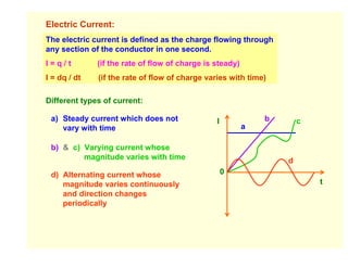
Electric Current:
The electric current is defined as the charge flowing through
any section of the conductor in one second.
I=q/t         (if the rate of flow of charge is steady)
I = dq / dt   (if the rate of flow of charge varies with time)

Different types of current:

 a) Steady current which does not               I             b       c
    vary with time                                        a

 b) & c) Varying current whose
         magnitude varies with time                               d
 d) Alternating current whose                       0
    magnitude varies continuously                                         t
    and direction changes
    periodically
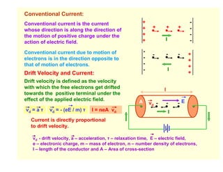
Conventional Current:
Conventional current is the current                    +                              -
                                                       +       +         +       +    -
whose direction is along the direction of
the motion of positive charge under the                +                              -
                                                       +             I                -
action of electric field.
                                                          -
Conventional current due to motion of                     -    -         -       -    +
electrons is in the direction opposite to                 -                           +
that of motion of electrons.                                                          +
                                                          -              I
Drift Velocity and Current:                                                           +
Drift velocity is defined as the velocity
with which the free electrons get drifted                            l
towards the positive terminal under the
effect of the applied electric field.                 A       vd -       -       -E
vd = a τ   vd = - (eE / m) τ   I = neA vd                                    I
  Current is directly proportional
  to drift velocity.

   vd - drift velocity, a – acceleration, τ – relaxation time, E – electric field,
   e – electronic charge, m – mass of electron, n – number density of electrons,
   l – length of the conductor and A – Area of cross-section
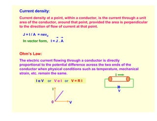
Current density:
Current density at a point, within a conductor, is the current through a unit
area of the conductor, around that point, provided the area is perpendicular
to the direction of flow of current at that point.

  J = I / A = nevd
  In vector form, I = J . A


Ohm’s Law:
The electric current flowing through a conductor is directly
proportional to the potential difference across the two ends of the
conductor when physical conditions such as temperature, mechanical
strain, etc. remain the same.                             I
          IαV    or V α I or V = R I

                     I                                     V


                     0        V
Resistance:
The resistance of conductor is the opposition offered by the
conductor to the flow of electric current through it.

                      R=V / I

Resistance in terms of physical features of the conductor:
     I = neA | vd |                                           m
                                                  where ρ =
                                         l                     ne2τ
                                  R =ρ            is resistivity or
     I = neA (e |E| / m) τ               A
                                                  specific resistance
        ne2Aτ V
     I=                         Resistance is directly proportional to
          m l
                                length and inversely proportional to
     V    ml                    cross-sectional area of the conductor
       =                        and depends on nature of material.
     I   ne2Aτ
            m    l              Resistivity depends upon nature of
     R =                        material and not on the geometrical
           ne2τ A               dimensions of the conductor.
Relations between vd , ρ, l, E, J and V:
                                                                When temperature
ρ = E / J = E / nevd              (since, J = I / A = nevd )    increases,
                                                                vd decreases and ρ
vd = E /(neρ)
                                                                increases.
vd = V /(neρl)                    (since, E = V / l )           When l increases, vd
                                                                decreases.

Conductance and conductivity:
Conductance is the reciprocal of resistance. Its S.I unit is mho.
Conductivity is the reciprocal of resistivity. Its S.I unit is mho / m.

Temperature dependence of Resistances:
       m      l        When temperature increases, the no. of collisions
R =                    increases due to more internal energy and relaxation time
      ne2τ A
                       decreases. Therefore, Resistance increases.
Temperature coefficient of Resistance:              R0 – Resistance at 0°
                                                                        C
      Rt – R0                 R2 – R1               Rt – Resistance at t°
                                                                        C
α=                or   α=
       R0 t                  R1t2 – R2t1            R1 – Resistance at t1°
                                                                         C

      If R2 < R1, then α is – ve.                   R2 – Resistance at t2°
                                                                         C
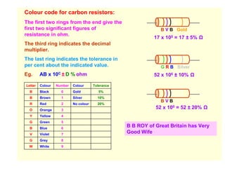
Colour code for carbon resistors:
The first two rings from the end give the
first two significant figures of                                B V B Gold
resistance in ohm.
                                                             17 x 100 = 17 ± 5%
The third ring indicates the decimal
multiplier.
The last ring indicates the tolerance in
per cent about the indicated value.                             G R B Silver
Eg.      AB x 10C ± D % ohm                                  52 x 106 ± 10%

Letter   Colour   Number   Colour      Tolerance
  B      Black      0      Gold           5%
  B      Brown      1      Silver        10%
                                                                BVB
  R      Red        2      No colour     20%
  O      Orange     3
                                                              52 x 100 = 52 ± 20%
  Y      Yellow     4
  G      Green      5
  B      Blue       6
                                                   B B ROY of Great Britain has Very
  V      Violet     7
                                                   Good Wife
  G      Grey       8
  W      White      9
Another Colour code for carbon resistors:
i)   The colour of the body gives the first
     significant figure.                           Red Ends   Yellow Body     Gold Ring
ii) The colour of the ends gives the second
                                                                 Blue Dot
    significant figure.
iii) The colour of the dot gives the decimal                  YRB Gold
     multipier.
                                                              42 x 106 ± 5%
iv) The colour of the ring gives the
    tolerance.

Series combination of resistors:
                                              R = R1 + R2 + R3

        R1         R2        R3               R is greater than the greatest of all.

Parallel combination of resistors:
                   R1
                                              1/R =1/R1 + 1/R2 + 1/R3
                   R2
                                              R is smaller than the smallest of all.
                   R3
Sources of emf:

The electro motive force is the maximum potential difference between the
two electrodes of the cell when no current is drawn from the cell.

Comparison of EMF and P.D:
     EMF                                Potential Difference
 1   EMF is the maximum potential       P.D is the difference of potentials
     difference between the two         between any two points in a closed
     electrodes of the cell when no     circuit.
     current is drawn from the cell
     i.e. when the circuit is open.
 2   It is independent of the           It is proportional to the resistance
     resistance of the circuit.         between the given points.

 3   The term ‘emf’ is used only for    It is measured between any two
     the source of emf.                 points of the circuit.

 4   It is greater than the potential   However, p.d. is greater than emf
     difference between any two         when the cell is being charged.
     points in a circuit.
Internal Resistance of a cell:
The opposition offered by the electrolyte of the cell to the flow of electric
current through it is called the internal resistance of the cell.
Factors affecting Internal Resistance of a cell:
i)   Larger the separation between the electrodes of the cell, more the length
     of the electrolyte through which current has to flow and consequently a
     higher value of internal resistance.
ii) Greater the conductivity of the electrolyte, lesser is the internal resistance
    of the cell. i.e. internal resistance depends on the nature of the electrolyte.
iii) The internal resistance of a cell is inversely proportional to the common
     area of the electrodes dipping in the electrolyte.
iv) The internal resistance of a cell depends on the nature of the electrodes.
    E =V+v
       = IR + Ir                                              E r
       = I (R + r)                                               v
                                                     I                      I
     I = E / (R + r)
                                                               R
     This relation is called circuit equation.
                                                                V
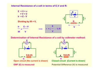
Internal Resistance of a cell in terms of E,V and R:

      E =V+v                                                            E r
         = V + Ir
      Ir = E - V                                                         v
                                                              I                  I
      Dividing by IR = V,                                               R

      Ir       E–V                       E                               V
           =                      r =(           - 1) R
      IR           V                     V


Determination of Internal Resistance of a cell by voltmeter method:
                       V                                      V
               +                                          +

                           r                                      r

                                             I                               I
                       R.B (R)                                R.B (R)

           K                                     K
  Open circuit (No current is drawn)     Closed circuit (Current is drawn)
  EMF (E) is measured                    Potential Difference (V) is measured
Cells in Series combination:
Cells are connected in series when they are joined end to end so that the
same quantity of electricity must flow through each cell.
NOTE:
                                                    E r            E r           E r
1. The emf of the battery is the
   sum of the individual emfs
                                      I                                                          I
2. The current in each cell is the
   same and is identical with the                                   R
   current in the entire
   arrangement.                                                     V
3. The total internal resistance of
   the battery is the sum of the
   individual internal resistances.

  Total emf of the battery                       = nE       (for n no. of identical cells)
  Total Internal resistance of the battery = nr
  Total resistance of the circuit                = nr + R

                            (i) If R << nr, then I = E / r (ii) If nr << R, then I = n (E / R)
                   nE
   Current I =               Conclusion: When internal resistance is negligible in
                 nr + R      comparison to the external resistance, then the cells are
                             connected in series to get maximum current.
Cells in Parallel combination:
Cells are said to be connected in parallel when they are joined positive to
positive and negative to negative such that current is divided between the cells.
                                                                              E r
NOTE:
1. The emf of the battery is the same as that of a
   single cell.
                                                                              E r
2. The current in the external circuit is divided equally
   among the cells.
3. The reciprocal of the total internal resistance is the                     E r
   sum of the reciprocals of the individual internal            I                                 I
   resistances.

Total emf of the battery                        = E                             R

Total Internal resistance of the battery = r / n                                V
Total resistance of the circuit                = (r / n) + R


                            (i) If R << r/n, then I = n(E / r) (ii) If r/n << R, then I = E / R
                   nE
   Current I =               Conclusion: When external resistance is negligible in
                  nR + r     comparison to the internal resistance, then the cells are
                             connected in parallel to get maximum current.
CURRENT ELECTRICITY - II


1. Kirchhoff’s Laws of electricity
2. Wheatstone Bridge
3. Metre Bridge
4. Potentiometer
   i) Principle
   ii) Comparison of emf of primary cells
KIRCHHOFF’S LAWS:
I Law or Current Law or Junction Rule:
The algebraic sum of electric currents at a junction in any
electrical network is always zero.

                                I1        I2

                                               I3   I1 - I2 - I3 + I4 - I5 = 0
                                     O
                           I5
                                     I4
  Sign Conventions:
  1. The incoming currents towards the junction are taken positive.
  2. The outgoing currents away from the junction are taken negative.


  Note: The charges cannot accumulate at a junction. The number
  of charges that arrive at a junction in a given time must leave in
  the same time in accordance with conservation of charges.
II Law or Voltage Law or Loop Rule:
The algebraic sum of all the potential drops and emf’s along any
closed path in an electrical network is always zero.
       I1 E1      R1        I1
   A                           B              Loop ABCA:

                       R2                       - E1 + I1.R1 + (I1 + I2).R2 = 0
  I2         I1 + I2                 I1
                                                Loop ACDA:
   D                             C
        I2             R3   I2                  - (I1 + I2).R2 - I2.R3 + E2 = 0
               E2
Sign Conventions:
1. The emf is taken negative when we traverse from positive to negative
   terminal of the cell through the electrolyte.
2. The emf is taken positive when we traverse from negative to positive
   terminal of the cell through the electrolyte.

   The potential falls along the direction of current in a current path
   and it rises along the direction opposite to the current path.

3. The potential fall is taken negative.     Note: The path can be traversed
4. The potential rise is taken positive.     in clockwise or anticlockwise
                                             direction of the loop.
B
Wheatstone Bridge:
                                                            P                      Q
Currents through the arms are assumed by           I1                                       I1 - Ig
applying Kirchhoff’s Junction Rule.                                      Ig

Applying Kirchhoff’s Loop Rule for:            A                         G                        C
Loop ABDA:
-I1.P - Ig.G + (I - I1).R = 0                       R                                  S
                                                        I - I1
                                               I                              I - I1 + Ig             I
Loop BCDB:
- (I1 - Ig).Q + (I - I1 + Ig).S + Ig.G = 0                               D


When Ig = 0, the bridge is said to balanced.                 I                     I
                                                                     E


  By manipulating the above equations, we get       P            R
                                                    Q            S
Metre Bridge:                             R.B (R)                        X

 Metre Bridge is based
 on the principle of                                                 G
 Wheatstone Bridge.
                                 A                                              B
When the galvanometer                          l cm              J 100 - l cm
current is made zero by
adjusting the jockey
                                                                 K
position on the metre-                        E
bridge wire for the given
values of known and
unknown resistances,

      R     RAJ             R   AJ           R           l           (Since,
                                                                     Resistance α
      X     RJB             X   JB           X         100 - l       length)


                  Therefore,     X = R (100 – l) ⁄ l
Potentiometer:                             I
                                                           +

Principle:                                                     V
                                  E            A
                                                     0     l cm    J       100
V=IR
                                  A            200
  = I ρl/A                             +                                   300
If the constant current flows     Rh           B     400
through the potentiometer wire
of uniform cross sectional area
(A) and uniform composition                K
of material (ρ), then


V = Kl or      Vαl

V /l is a constant.
                                                               V
The potential difference across any length of a wire
of uniform cross-section and uniform composition is
proportional to its length when a constant current
                                                               0
flows through it.                                                      l
Comparison of emf’s using
                                                               E1
Potentiometer:                                                        R.B
                                               I               +                  G
The balance point is                                           +
obtained for the cell when                                     E2
the potential at a point on           E             A
                                                         0                l2 J2   100
the potentiometer wire is
equal and opposite to the             A            200          l1   J1
emf of the cell.                           +
                                                                                  300
                                      Rh            B
          E1 = VAJ1 = I ρl1 /A                           400

          E2 = VAJ2 = I ρl2 /A
                                                K
          E1 / E2 = l1 /l2
Note:
The balance point will not be obtained on the potentiometer wire if the fall
of potential along the potentiometer wire is less than the emf of the cell to
be measured.
The working of the potentiometer is based on null deflection method. So
the resistance of the wire becomes infinite. Thus potentiometer can be
regarded as an ideal voltmeter.

More Related Content

What's hot

Class 12th physics current electricity part 2 ppt
Class 12th physics current electricity part 2 ppt Class 12th physics current electricity part 2 ppt
Class 12th physics current electricity part 2 ppt
Arpit Meena
 
Electrostatics Class 12- Part 4
Electrostatics Class 12- Part 4Electrostatics Class 12- Part 4
Electrostatics Class 12- Part 4Self-employed
 
Semiconductor Devices Class 12 Part-1
Semiconductor Devices Class 12 Part-1Semiconductor Devices Class 12 Part-1
Semiconductor Devices Class 12 Part-1Self-employed
 
Semiconductor Devices Class 12 Part-3
Semiconductor Devices Class 12 Part-3Semiconductor Devices Class 12 Part-3
Semiconductor Devices Class 12 Part-3Self-employed
 
Class 12th physics magnetism ppt
Class 12th physics magnetism pptClass 12th physics magnetism ppt
Class 12th physics magnetism ppt
Arpit Meena
 
Alternating Currents Class 12
Alternating Currents Class 12Alternating Currents Class 12
Alternating Currents Class 12Self-employed
 
Class 12th Physics wave optics ppt
Class 12th Physics wave optics pptClass 12th Physics wave optics ppt
Class 12th Physics wave optics ppt
Arpit Meena
 
Magnetic Effects Of Current Class 12 Part-1
Magnetic Effects Of Current Class 12 Part-1Magnetic Effects Of Current Class 12 Part-1
Magnetic Effects Of Current Class 12 Part-1Self-employed
 
Chapter 2 physics 12 (a)
Chapter  2 physics 12 (a)Chapter  2 physics 12 (a)
Chapter 2 physics 12 (a)
snigdhajain22
 
Chapter 3: AC Sources and AC Characteristic
Chapter 3: AC Sources and AC CharacteristicChapter 3: AC Sources and AC Characteristic
Chapter 3: AC Sources and AC Characteristic
JeremyLauKarHei
 
Wave Optics Class 12 Part-2
Wave Optics Class 12 Part-2Wave Optics Class 12 Part-2
Wave Optics Class 12 Part-2Self-employed
 
Class 12th Physics Atom nuclei PPt
Class 12th Physics Atom nuclei PPtClass 12th Physics Atom nuclei PPt
Class 12th Physics Atom nuclei PPt
Arpit Meena
 
3m magnetic-effects-of-current-magnetism
3m magnetic-effects-of-current-magnetism3m magnetic-effects-of-current-magnetism
3m magnetic-effects-of-current-magnetismPrayash Mohapatra
 
Ray Optics Class 12 Part-1
Ray Optics Class 12 Part-1Ray Optics Class 12 Part-1
Ray Optics Class 12 Part-1Self-employed
 
Electrostatics 4
Electrostatics 4Electrostatics 4
Electrostatics 4
Shwetha Inspiring
 
PHY PUC 2 MOVING CHARGE AND MAGNETISM
PHY PUC 2 MOVING CHARGE AND MAGNETISMPHY PUC 2 MOVING CHARGE AND MAGNETISM
PHY PUC 2 MOVING CHARGE AND MAGNETISM
study material
 
Photoelectric Effect And Dual Nature Of Matter And Radiation Class 12
Photoelectric Effect And Dual Nature Of Matter And Radiation Class 12Photoelectric Effect And Dual Nature Of Matter And Radiation Class 12
Photoelectric Effect And Dual Nature Of Matter And Radiation Class 12Self-employed
 
Ray Optics Class 12 Part-2
Ray Optics Class 12 Part-2Ray Optics Class 12 Part-2
Ray Optics Class 12 Part-2Self-employed
 
Electrostatic potential and capacitance
Electrostatic potential and capacitanceElectrostatic potential and capacitance
Electrostatic potential and capacitance
EdigniteNGO
 

What's hot (20)

Class 12th physics current electricity part 2 ppt
Class 12th physics current electricity part 2 ppt Class 12th physics current electricity part 2 ppt
Class 12th physics current electricity part 2 ppt
 
Electrostatics Class 12- Part 4
Electrostatics Class 12- Part 4Electrostatics Class 12- Part 4
Electrostatics Class 12- Part 4
 
Semiconductor Devices Class 12 Part-1
Semiconductor Devices Class 12 Part-1Semiconductor Devices Class 12 Part-1
Semiconductor Devices Class 12 Part-1
 
Semiconductor Devices Class 12 Part-3
Semiconductor Devices Class 12 Part-3Semiconductor Devices Class 12 Part-3
Semiconductor Devices Class 12 Part-3
 
Class 12th physics magnetism ppt
Class 12th physics magnetism pptClass 12th physics magnetism ppt
Class 12th physics magnetism ppt
 
Alternating Currents Class 12
Alternating Currents Class 12Alternating Currents Class 12
Alternating Currents Class 12
 
Class 12th Physics wave optics ppt
Class 12th Physics wave optics pptClass 12th Physics wave optics ppt
Class 12th Physics wave optics ppt
 
Magnetic Effects Of Current Class 12 Part-1
Magnetic Effects Of Current Class 12 Part-1Magnetic Effects Of Current Class 12 Part-1
Magnetic Effects Of Current Class 12 Part-1
 
Chapter 2 physics 12 (a)
Chapter  2 physics 12 (a)Chapter  2 physics 12 (a)
Chapter 2 physics 12 (a)
 
Chapter 3: AC Sources and AC Characteristic
Chapter 3: AC Sources and AC CharacteristicChapter 3: AC Sources and AC Characteristic
Chapter 3: AC Sources and AC Characteristic
 
Magnetism
MagnetismMagnetism
Magnetism
 
Wave Optics Class 12 Part-2
Wave Optics Class 12 Part-2Wave Optics Class 12 Part-2
Wave Optics Class 12 Part-2
 
Class 12th Physics Atom nuclei PPt
Class 12th Physics Atom nuclei PPtClass 12th Physics Atom nuclei PPt
Class 12th Physics Atom nuclei PPt
 
3m magnetic-effects-of-current-magnetism
3m magnetic-effects-of-current-magnetism3m magnetic-effects-of-current-magnetism
3m magnetic-effects-of-current-magnetism
 
Ray Optics Class 12 Part-1
Ray Optics Class 12 Part-1Ray Optics Class 12 Part-1
Ray Optics Class 12 Part-1
 
Electrostatics 4
Electrostatics 4Electrostatics 4
Electrostatics 4
 
PHY PUC 2 MOVING CHARGE AND MAGNETISM
PHY PUC 2 MOVING CHARGE AND MAGNETISMPHY PUC 2 MOVING CHARGE AND MAGNETISM
PHY PUC 2 MOVING CHARGE AND MAGNETISM
 
Photoelectric Effect And Dual Nature Of Matter And Radiation Class 12
Photoelectric Effect And Dual Nature Of Matter And Radiation Class 12Photoelectric Effect And Dual Nature Of Matter And Radiation Class 12
Photoelectric Effect And Dual Nature Of Matter And Radiation Class 12
 
Ray Optics Class 12 Part-2
Ray Optics Class 12 Part-2Ray Optics Class 12 Part-2
Ray Optics Class 12 Part-2
 
Electrostatic potential and capacitance
Electrostatic potential and capacitanceElectrostatic potential and capacitance
Electrostatic potential and capacitance
 

Viewers also liked

How to prepare for board exams
How to prepare for board examsHow to prepare for board exams
How to prepare for board exams
Aditi Sharma
 
Current electricity (electricity)
Current electricity (electricity)Current electricity (electricity)
Current electricity (electricity)
Juan Apolinario Reyes
 
11 - DC Electricity
11 - DC Electricity11 - DC Electricity
11 - DC Electricitymatcol
 
Presentation1current electricity
Presentation1current electricityPresentation1current electricity
Presentation1current electricity
terna vidyalaya and junior college
 
Current electricity
Current electricityCurrent electricity
Current electricity14choiyu
 
Basic current electricity notes (3)
Basic current electricity notes  (3)Basic current electricity notes  (3)
Basic current electricity notes (3)9892642432p
 
Current and electricity
Current and electricityCurrent and electricity
Current and electricity
Seyid Kadher
 
ALL ABOUT ELECTRIC CIRCUITS AND STATIC ELECTRICITY
ALL ABOUT ELECTRIC CIRCUITS AND STATIC ELECTRICITYALL ABOUT ELECTRIC CIRCUITS AND STATIC ELECTRICITY
ALL ABOUT ELECTRIC CIRCUITS AND STATIC ELECTRICITY
Sciencetutors E-learning Media
 
Current electricity
Current   electricityCurrent   electricity
Current electricity
Prarabdh Garg
 
Engineering physics 1(Electrical conductivity)
Engineering physics 1(Electrical conductivity)Engineering physics 1(Electrical conductivity)
Engineering physics 1(Electrical conductivity)
Nexus
 
Electricity
ElectricityElectricity
Electricity
ngibellini
 
Circuits and conductors
Circuits and conductorsCircuits and conductors
Circuits and conductors
isamadero79
 
Physics - Current Electricity Notes for JEE Main 2015
Physics - Current Electricity Notes for JEE Main 2015Physics - Current Electricity Notes for JEE Main 2015
Physics - Current Electricity Notes for JEE Main 2015
Ednexa
 
Unidad 7 MAGNETISM
Unidad 7 MAGNETISMUnidad 7 MAGNETISM
Unidad 7 MAGNETISM
María José Mora
 
Unit 1 Ccurrent Electricity
Unit 1 Ccurrent ElectricityUnit 1 Ccurrent Electricity
Unit 1 Ccurrent ElectricityBruce Coulter
 
Exp SPA - Chp 17 Current of Electricity
Exp SPA - Chp 17 Current of ElectricityExp SPA - Chp 17 Current of Electricity
Exp SPA - Chp 17 Current of Electricity
harrywwh
 
Circuit (symbols,dimmer and brighter)
Circuit (symbols,dimmer and brighter)Circuit (symbols,dimmer and brighter)
Circuit (symbols,dimmer and brighter)
Maha Hussain
 
Static AND current electricity
Static AND current electricityStatic AND current electricity
Static AND current electricity
alfonsodios
 

Viewers also liked (20)

Phy1
Phy1Phy1
Phy1
 
How to prepare for board exams
How to prepare for board examsHow to prepare for board exams
How to prepare for board exams
 
Current electricity (electricity)
Current electricity (electricity)Current electricity (electricity)
Current electricity (electricity)
 
11 - DC Electricity
11 - DC Electricity11 - DC Electricity
11 - DC Electricity
 
Presentation1current electricity
Presentation1current electricityPresentation1current electricity
Presentation1current electricity
 
Current electricity
Current electricityCurrent electricity
Current electricity
 
Basic current electricity notes (3)
Basic current electricity notes  (3)Basic current electricity notes  (3)
Basic current electricity notes (3)
 
Current and electricity
Current and electricityCurrent and electricity
Current and electricity
 
Electricity
ElectricityElectricity
Electricity
 
ALL ABOUT ELECTRIC CIRCUITS AND STATIC ELECTRICITY
ALL ABOUT ELECTRIC CIRCUITS AND STATIC ELECTRICITYALL ABOUT ELECTRIC CIRCUITS AND STATIC ELECTRICITY
ALL ABOUT ELECTRIC CIRCUITS AND STATIC ELECTRICITY
 
Current electricity
Current   electricityCurrent   electricity
Current electricity
 
Engineering physics 1(Electrical conductivity)
Engineering physics 1(Electrical conductivity)Engineering physics 1(Electrical conductivity)
Engineering physics 1(Electrical conductivity)
 
Electricity
ElectricityElectricity
Electricity
 
Circuits and conductors
Circuits and conductorsCircuits and conductors
Circuits and conductors
 
Physics - Current Electricity Notes for JEE Main 2015
Physics - Current Electricity Notes for JEE Main 2015Physics - Current Electricity Notes for JEE Main 2015
Physics - Current Electricity Notes for JEE Main 2015
 
Unidad 7 MAGNETISM
Unidad 7 MAGNETISMUnidad 7 MAGNETISM
Unidad 7 MAGNETISM
 
Unit 1 Ccurrent Electricity
Unit 1 Ccurrent ElectricityUnit 1 Ccurrent Electricity
Unit 1 Ccurrent Electricity
 
Exp SPA - Chp 17 Current of Electricity
Exp SPA - Chp 17 Current of ElectricityExp SPA - Chp 17 Current of Electricity
Exp SPA - Chp 17 Current of Electricity
 
Circuit (symbols,dimmer and brighter)
Circuit (symbols,dimmer and brighter)Circuit (symbols,dimmer and brighter)
Circuit (symbols,dimmer and brighter)
 
Static AND current electricity
Static AND current electricityStatic AND current electricity
Static AND current electricity
 

Similar to 2m current electricity

Chapter vii direct current circuits new
Chapter vii direct current circuits newChapter vii direct current circuits new
Chapter vii direct current circuits newrozi arrozi
 
2currentelectricity1-140315124205-phpapp01
2currentelectricity1-140315124205-phpapp012currentelectricity1-140315124205-phpapp01
2currentelectricity1-140315124205-phpapp01Aman Meena
 
2_current_electricity_1.pptnefipnipdannaffkn
2_current_electricity_1.pptnefipnipdannaffkn2_current_electricity_1.pptnefipnipdannaffkn
2_current_electricity_1.pptnefipnipdannaffkn
Karthik537368
 
2_current_electricity_1.pptcdasdDdDddddddD
2_current_electricity_1.pptcdasdDdDddddddD2_current_electricity_1.pptcdasdDdDddddddD
2_current_electricity_1.pptcdasdDdDddddddD
Karthik537368
 
2_current_electricity_1.pptcdasdDdDddddddD
2_current_electricity_1.pptcdasdDdDddddddD2_current_electricity_1.pptcdasdDdDddddddD
2_current_electricity_1.pptcdasdDdDddddddD
Karthik537368
 
2currentelectricity1-140315124205-phpapp01 (1).pdf
2currentelectricity1-140315124205-phpapp01 (1).pdf2currentelectricity1-140315124205-phpapp01 (1).pdf
2currentelectricity1-140315124205-phpapp01 (1).pdf
2kGamer3
 
current electricity PHYSICS CHAPTER 2.ppt
current electricity     PHYSICS CHAPTER 2.pptcurrent electricity     PHYSICS CHAPTER 2.ppt
current electricity PHYSICS CHAPTER 2.ppt
HarshPawar30
 
Ch 26-current and resistance
Ch 26-current and resistanceCh 26-current and resistance
Ch 26-current and resistance
Muhammad Junaid
 
2_current_electricity_1.ppt
2_current_electricity_1.ppt2_current_electricity_1.ppt
2_current_electricity_1.ppt
TayyabShabir
 
2_current_electricity_1.ppt
2_current_electricity_1.ppt2_current_electricity_1.ppt
2_current_electricity_1.ppt
TSANROSEBASTIN
 
Tunnel Diode (Esaki Diode )
Tunnel Diode (Esaki Diode )Tunnel Diode (Esaki Diode )
Tunnel Diode (Esaki Diode )
Soudip Sinha Roy
 
ELECTRICITY.ppt-converted.pptx
ELECTRICITY.ppt-converted.pptxELECTRICITY.ppt-converted.pptx
ELECTRICITY.ppt-converted.pptx
SiddalingeshwarSiddu
 
factors affecting internal resistance/emf of the cell
factors affecting internal resistance/emf of the cellfactors affecting internal resistance/emf of the cell
factors affecting internal resistance/emf of the cell
Yogesh Baghel
 
Electicity notes by r k chaudhari sir
Electicity notes by r k chaudhari sirElecticity notes by r k chaudhari sir
Electicity notes by r k chaudhari sir
raghvendra0123
 
Chapter 02
Chapter 02Chapter 02
Chapter 02
Ahmar Iqbal
 
Ee study notes
Ee study notesEe study notes
Ee study notesCK Yang
 
C.12 PHYSICS CURRENT ELECTRICITY notes.pdf
C.12 PHYSICS CURRENT ELECTRICITY notes.pdfC.12 PHYSICS CURRENT ELECTRICITY notes.pdf
C.12 PHYSICS CURRENT ELECTRICITY notes.pdf
ZiauddinKhan34
 
Diodes and semiconductors - an introduction
Diodes and semiconductors - an introductionDiodes and semiconductors - an introduction
Diodes and semiconductors - an introduction
University of Essex
 
Resistance
ResistanceResistance
Resistance
Daniel McClelland
 
Electricity
ElectricityElectricity

Similar to 2m current electricity (20)

Chapter vii direct current circuits new
Chapter vii direct current circuits newChapter vii direct current circuits new
Chapter vii direct current circuits new
 
2currentelectricity1-140315124205-phpapp01
2currentelectricity1-140315124205-phpapp012currentelectricity1-140315124205-phpapp01
2currentelectricity1-140315124205-phpapp01
 
2_current_electricity_1.pptnefipnipdannaffkn
2_current_electricity_1.pptnefipnipdannaffkn2_current_electricity_1.pptnefipnipdannaffkn
2_current_electricity_1.pptnefipnipdannaffkn
 
2_current_electricity_1.pptcdasdDdDddddddD
2_current_electricity_1.pptcdasdDdDddddddD2_current_electricity_1.pptcdasdDdDddddddD
2_current_electricity_1.pptcdasdDdDddddddD
 
2_current_electricity_1.pptcdasdDdDddddddD
2_current_electricity_1.pptcdasdDdDddddddD2_current_electricity_1.pptcdasdDdDddddddD
2_current_electricity_1.pptcdasdDdDddddddD
 
2currentelectricity1-140315124205-phpapp01 (1).pdf
2currentelectricity1-140315124205-phpapp01 (1).pdf2currentelectricity1-140315124205-phpapp01 (1).pdf
2currentelectricity1-140315124205-phpapp01 (1).pdf
 
current electricity PHYSICS CHAPTER 2.ppt
current electricity     PHYSICS CHAPTER 2.pptcurrent electricity     PHYSICS CHAPTER 2.ppt
current electricity PHYSICS CHAPTER 2.ppt
 
Ch 26-current and resistance
Ch 26-current and resistanceCh 26-current and resistance
Ch 26-current and resistance
 
2_current_electricity_1.ppt
2_current_electricity_1.ppt2_current_electricity_1.ppt
2_current_electricity_1.ppt
 
2_current_electricity_1.ppt
2_current_electricity_1.ppt2_current_electricity_1.ppt
2_current_electricity_1.ppt
 
Tunnel Diode (Esaki Diode )
Tunnel Diode (Esaki Diode )Tunnel Diode (Esaki Diode )
Tunnel Diode (Esaki Diode )
 
ELECTRICITY.ppt-converted.pptx
ELECTRICITY.ppt-converted.pptxELECTRICITY.ppt-converted.pptx
ELECTRICITY.ppt-converted.pptx
 
factors affecting internal resistance/emf of the cell
factors affecting internal resistance/emf of the cellfactors affecting internal resistance/emf of the cell
factors affecting internal resistance/emf of the cell
 
Electicity notes by r k chaudhari sir
Electicity notes by r k chaudhari sirElecticity notes by r k chaudhari sir
Electicity notes by r k chaudhari sir
 
Chapter 02
Chapter 02Chapter 02
Chapter 02
 
Ee study notes
Ee study notesEe study notes
Ee study notes
 
C.12 PHYSICS CURRENT ELECTRICITY notes.pdf
C.12 PHYSICS CURRENT ELECTRICITY notes.pdfC.12 PHYSICS CURRENT ELECTRICITY notes.pdf
C.12 PHYSICS CURRENT ELECTRICITY notes.pdf
 
Diodes and semiconductors - an introduction
Diodes and semiconductors - an introductionDiodes and semiconductors - an introduction
Diodes and semiconductors - an introduction
 
Resistance
ResistanceResistance
Resistance
 
Electricity
ElectricityElectricity
Electricity
 

More from Prayash Mohapatra

Idea Challenge - Rules
Idea Challenge - RulesIdea Challenge - Rules
Idea Challenge - Rules
Prayash Mohapatra
 
Guidelines for attempting the English paper Class XII
Guidelines for attempting the English paper Class XIIGuidelines for attempting the English paper Class XII
Guidelines for attempting the English paper Class XIIPrayash Mohapatra
 
7m dual nature_of_matter__radiation
7m dual nature_of_matter__radiation7m dual nature_of_matter__radiation
7m dual nature_of_matter__radiationPrayash Mohapatra
 
4m electromagnetic induction__alternating_currents
4m electromagnetic induction__alternating_currents4m electromagnetic induction__alternating_currents
4m electromagnetic induction__alternating_currentsPrayash Mohapatra
 

More from Prayash Mohapatra (10)

Idea Challenge - Rules
Idea Challenge - RulesIdea Challenge - Rules
Idea Challenge - Rules
 
Guidelines for attempting the English paper Class XII
Guidelines for attempting the English paper Class XIIGuidelines for attempting the English paper Class XII
Guidelines for attempting the English paper Class XII
 
9m electronic devices
9m electronic devices9m electronic devices
9m electronic devices
 
8m atoms _nuclei
8m atoms _nuclei8m atoms _nuclei
8m atoms _nuclei
 
7m dual nature_of_matter__radiation
7m dual nature_of_matter__radiation7m dual nature_of_matter__radiation
7m dual nature_of_matter__radiation
 
6m optics
6m optics6m optics
6m optics
 
5m electromagnetic waves
5m electromagnetic waves5m electromagnetic waves
5m electromagnetic waves
 
4m electromagnetic induction__alternating_currents
4m electromagnetic induction__alternating_currents4m electromagnetic induction__alternating_currents
4m electromagnetic induction__alternating_currents
 
1m electrostatics
1m electrostatics1m electrostatics
1m electrostatics
 
10m communication systems
10m communication systems10m communication systems
10m communication systems
 

2m current electricity

  • 1. CURRENT ELECTRICITY - I 1. Electric Current 2. Conventional Current 3. Drift Velocity of electrons and current 4. Current Density 5. Ohm’s Law 6. Resistance, Resistivity, Conductance & Conductivity 7. Temperature dependence of resistance 8. Colour Codes for Carbon Resistors 9. Series and Parallel combination of resistors 10. EMF and Potential Difference of a cell 11. Internal Resistance of a cell 12. Series and Parallel combination of cells
  • 2. Electric Current: The electric current is defined as the charge flowing through any section of the conductor in one second. I=q/t (if the rate of flow of charge is steady) I = dq / dt (if the rate of flow of charge varies with time) Different types of current: a) Steady current which does not I b c vary with time a b) & c) Varying current whose magnitude varies with time d d) Alternating current whose 0 magnitude varies continuously t and direction changes periodically
  • 3. Conventional Current: Conventional current is the current + - + + + + - whose direction is along the direction of the motion of positive charge under the + - + I - action of electric field. - Conventional current due to motion of - - - - + electrons is in the direction opposite to - + that of motion of electrons. + - I Drift Velocity and Current: + Drift velocity is defined as the velocity with which the free electrons get drifted l towards the positive terminal under the effect of the applied electric field. A vd - - -E vd = a τ vd = - (eE / m) τ I = neA vd I Current is directly proportional to drift velocity. vd - drift velocity, a – acceleration, τ – relaxation time, E – electric field, e – electronic charge, m – mass of electron, n – number density of electrons, l – length of the conductor and A – Area of cross-section
  • 4. Current density: Current density at a point, within a conductor, is the current through a unit area of the conductor, around that point, provided the area is perpendicular to the direction of flow of current at that point. J = I / A = nevd In vector form, I = J . A Ohm’s Law: The electric current flowing through a conductor is directly proportional to the potential difference across the two ends of the conductor when physical conditions such as temperature, mechanical strain, etc. remain the same. I IαV or V α I or V = R I I V 0 V
  • 5. Resistance: The resistance of conductor is the opposition offered by the conductor to the flow of electric current through it. R=V / I Resistance in terms of physical features of the conductor: I = neA | vd | m where ρ = l ne2τ R =ρ is resistivity or I = neA (e |E| / m) τ A specific resistance ne2Aτ V I= Resistance is directly proportional to m l length and inversely proportional to V ml cross-sectional area of the conductor = and depends on nature of material. I ne2Aτ m l Resistivity depends upon nature of R = material and not on the geometrical ne2τ A dimensions of the conductor.
  • 6. Relations between vd , ρ, l, E, J and V: When temperature ρ = E / J = E / nevd (since, J = I / A = nevd ) increases, vd decreases and ρ vd = E /(neρ) increases. vd = V /(neρl) (since, E = V / l ) When l increases, vd decreases. Conductance and conductivity: Conductance is the reciprocal of resistance. Its S.I unit is mho. Conductivity is the reciprocal of resistivity. Its S.I unit is mho / m. Temperature dependence of Resistances: m l When temperature increases, the no. of collisions R = increases due to more internal energy and relaxation time ne2τ A decreases. Therefore, Resistance increases. Temperature coefficient of Resistance: R0 – Resistance at 0° C Rt – R0 R2 – R1 Rt – Resistance at t° C α= or α= R0 t R1t2 – R2t1 R1 – Resistance at t1° C If R2 < R1, then α is – ve. R2 – Resistance at t2° C
  • 7. Colour code for carbon resistors: The first two rings from the end give the first two significant figures of B V B Gold resistance in ohm. 17 x 100 = 17 ± 5% The third ring indicates the decimal multiplier. The last ring indicates the tolerance in per cent about the indicated value. G R B Silver Eg. AB x 10C ± D % ohm 52 x 106 ± 10% Letter Colour Number Colour Tolerance B Black 0 Gold 5% B Brown 1 Silver 10% BVB R Red 2 No colour 20% O Orange 3 52 x 100 = 52 ± 20% Y Yellow 4 G Green 5 B Blue 6 B B ROY of Great Britain has Very V Violet 7 Good Wife G Grey 8 W White 9
  • 8. Another Colour code for carbon resistors: i) The colour of the body gives the first significant figure. Red Ends Yellow Body Gold Ring ii) The colour of the ends gives the second Blue Dot significant figure. iii) The colour of the dot gives the decimal YRB Gold multipier. 42 x 106 ± 5% iv) The colour of the ring gives the tolerance. Series combination of resistors: R = R1 + R2 + R3 R1 R2 R3 R is greater than the greatest of all. Parallel combination of resistors: R1 1/R =1/R1 + 1/R2 + 1/R3 R2 R is smaller than the smallest of all. R3
  • 9. Sources of emf: The electro motive force is the maximum potential difference between the two electrodes of the cell when no current is drawn from the cell. Comparison of EMF and P.D: EMF Potential Difference 1 EMF is the maximum potential P.D is the difference of potentials difference between the two between any two points in a closed electrodes of the cell when no circuit. current is drawn from the cell i.e. when the circuit is open. 2 It is independent of the It is proportional to the resistance resistance of the circuit. between the given points. 3 The term ‘emf’ is used only for It is measured between any two the source of emf. points of the circuit. 4 It is greater than the potential However, p.d. is greater than emf difference between any two when the cell is being charged. points in a circuit.
  • 10. Internal Resistance of a cell: The opposition offered by the electrolyte of the cell to the flow of electric current through it is called the internal resistance of the cell. Factors affecting Internal Resistance of a cell: i) Larger the separation between the electrodes of the cell, more the length of the electrolyte through which current has to flow and consequently a higher value of internal resistance. ii) Greater the conductivity of the electrolyte, lesser is the internal resistance of the cell. i.e. internal resistance depends on the nature of the electrolyte. iii) The internal resistance of a cell is inversely proportional to the common area of the electrodes dipping in the electrolyte. iv) The internal resistance of a cell depends on the nature of the electrodes. E =V+v = IR + Ir E r = I (R + r) v I I I = E / (R + r) R This relation is called circuit equation. V
  • 11. Internal Resistance of a cell in terms of E,V and R: E =V+v E r = V + Ir Ir = E - V v I I Dividing by IR = V, R Ir E–V E V = r =( - 1) R IR V V Determination of Internal Resistance of a cell by voltmeter method: V V + + r r I I R.B (R) R.B (R) K K Open circuit (No current is drawn) Closed circuit (Current is drawn) EMF (E) is measured Potential Difference (V) is measured
  • 12. Cells in Series combination: Cells are connected in series when they are joined end to end so that the same quantity of electricity must flow through each cell. NOTE: E r E r E r 1. The emf of the battery is the sum of the individual emfs I I 2. The current in each cell is the same and is identical with the R current in the entire arrangement. V 3. The total internal resistance of the battery is the sum of the individual internal resistances. Total emf of the battery = nE (for n no. of identical cells) Total Internal resistance of the battery = nr Total resistance of the circuit = nr + R (i) If R << nr, then I = E / r (ii) If nr << R, then I = n (E / R) nE Current I = Conclusion: When internal resistance is negligible in nr + R comparison to the external resistance, then the cells are connected in series to get maximum current.
  • 13. Cells in Parallel combination: Cells are said to be connected in parallel when they are joined positive to positive and negative to negative such that current is divided between the cells. E r NOTE: 1. The emf of the battery is the same as that of a single cell. E r 2. The current in the external circuit is divided equally among the cells. 3. The reciprocal of the total internal resistance is the E r sum of the reciprocals of the individual internal I I resistances. Total emf of the battery = E R Total Internal resistance of the battery = r / n V Total resistance of the circuit = (r / n) + R (i) If R << r/n, then I = n(E / r) (ii) If r/n << R, then I = E / R nE Current I = Conclusion: When external resistance is negligible in nR + r comparison to the internal resistance, then the cells are connected in parallel to get maximum current.
  • 14. CURRENT ELECTRICITY - II 1. Kirchhoff’s Laws of electricity 2. Wheatstone Bridge 3. Metre Bridge 4. Potentiometer i) Principle ii) Comparison of emf of primary cells
  • 15. KIRCHHOFF’S LAWS: I Law or Current Law or Junction Rule: The algebraic sum of electric currents at a junction in any electrical network is always zero. I1 I2 I3 I1 - I2 - I3 + I4 - I5 = 0 O I5 I4 Sign Conventions: 1. The incoming currents towards the junction are taken positive. 2. The outgoing currents away from the junction are taken negative. Note: The charges cannot accumulate at a junction. The number of charges that arrive at a junction in a given time must leave in the same time in accordance with conservation of charges.
  • 16. II Law or Voltage Law or Loop Rule: The algebraic sum of all the potential drops and emf’s along any closed path in an electrical network is always zero. I1 E1 R1 I1 A B Loop ABCA: R2 - E1 + I1.R1 + (I1 + I2).R2 = 0 I2 I1 + I2 I1 Loop ACDA: D C I2 R3 I2 - (I1 + I2).R2 - I2.R3 + E2 = 0 E2 Sign Conventions: 1. The emf is taken negative when we traverse from positive to negative terminal of the cell through the electrolyte. 2. The emf is taken positive when we traverse from negative to positive terminal of the cell through the electrolyte. The potential falls along the direction of current in a current path and it rises along the direction opposite to the current path. 3. The potential fall is taken negative. Note: The path can be traversed 4. The potential rise is taken positive. in clockwise or anticlockwise direction of the loop.
  • 17. B Wheatstone Bridge: P Q Currents through the arms are assumed by I1 I1 - Ig applying Kirchhoff’s Junction Rule. Ig Applying Kirchhoff’s Loop Rule for: A G C Loop ABDA: -I1.P - Ig.G + (I - I1).R = 0 R S I - I1 I I - I1 + Ig I Loop BCDB: - (I1 - Ig).Q + (I - I1 + Ig).S + Ig.G = 0 D When Ig = 0, the bridge is said to balanced. I I E By manipulating the above equations, we get P R Q S
  • 18. Metre Bridge: R.B (R) X Metre Bridge is based on the principle of G Wheatstone Bridge. A B When the galvanometer l cm J 100 - l cm current is made zero by adjusting the jockey K position on the metre- E bridge wire for the given values of known and unknown resistances, R RAJ R AJ R l (Since, Resistance α X RJB X JB X 100 - l length) Therefore, X = R (100 – l) ⁄ l
  • 19. Potentiometer: I + Principle: V E A 0 l cm J 100 V=IR A 200 = I ρl/A + 300 If the constant current flows Rh B 400 through the potentiometer wire of uniform cross sectional area (A) and uniform composition K of material (ρ), then V = Kl or Vαl V /l is a constant. V The potential difference across any length of a wire of uniform cross-section and uniform composition is proportional to its length when a constant current 0 flows through it. l
  • 20. Comparison of emf’s using E1 Potentiometer: R.B I + G The balance point is + obtained for the cell when E2 the potential at a point on E A 0 l2 J2 100 the potentiometer wire is equal and opposite to the A 200 l1 J1 emf of the cell. + 300 Rh B E1 = VAJ1 = I ρl1 /A 400 E2 = VAJ2 = I ρl2 /A K E1 / E2 = l1 /l2 Note: The balance point will not be obtained on the potentiometer wire if the fall of potential along the potentiometer wire is less than the emf of the cell to be measured. The working of the potentiometer is based on null deflection method. So the resistance of the wire becomes infinite. Thus potentiometer can be regarded as an ideal voltmeter.