Downloaded 874 times
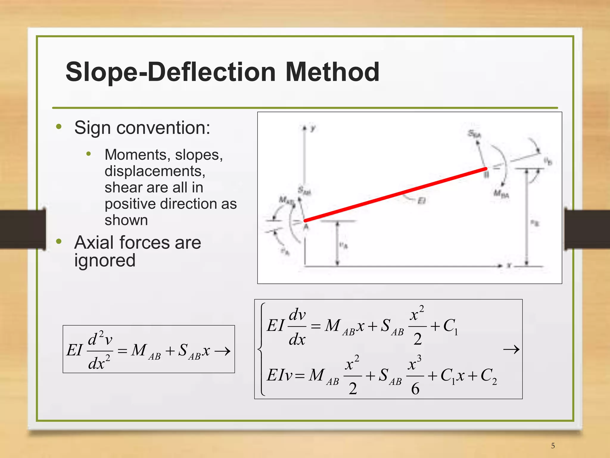
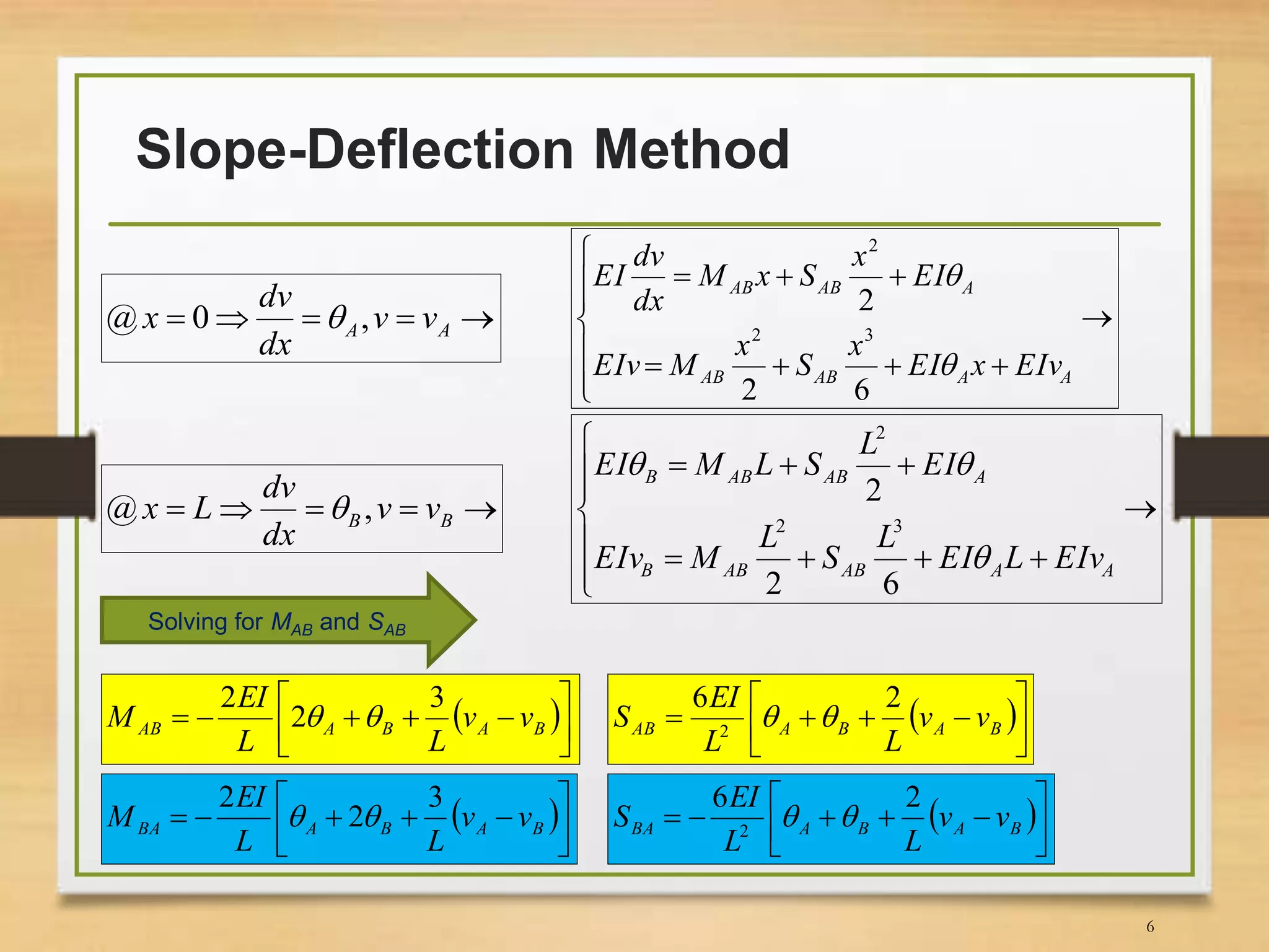
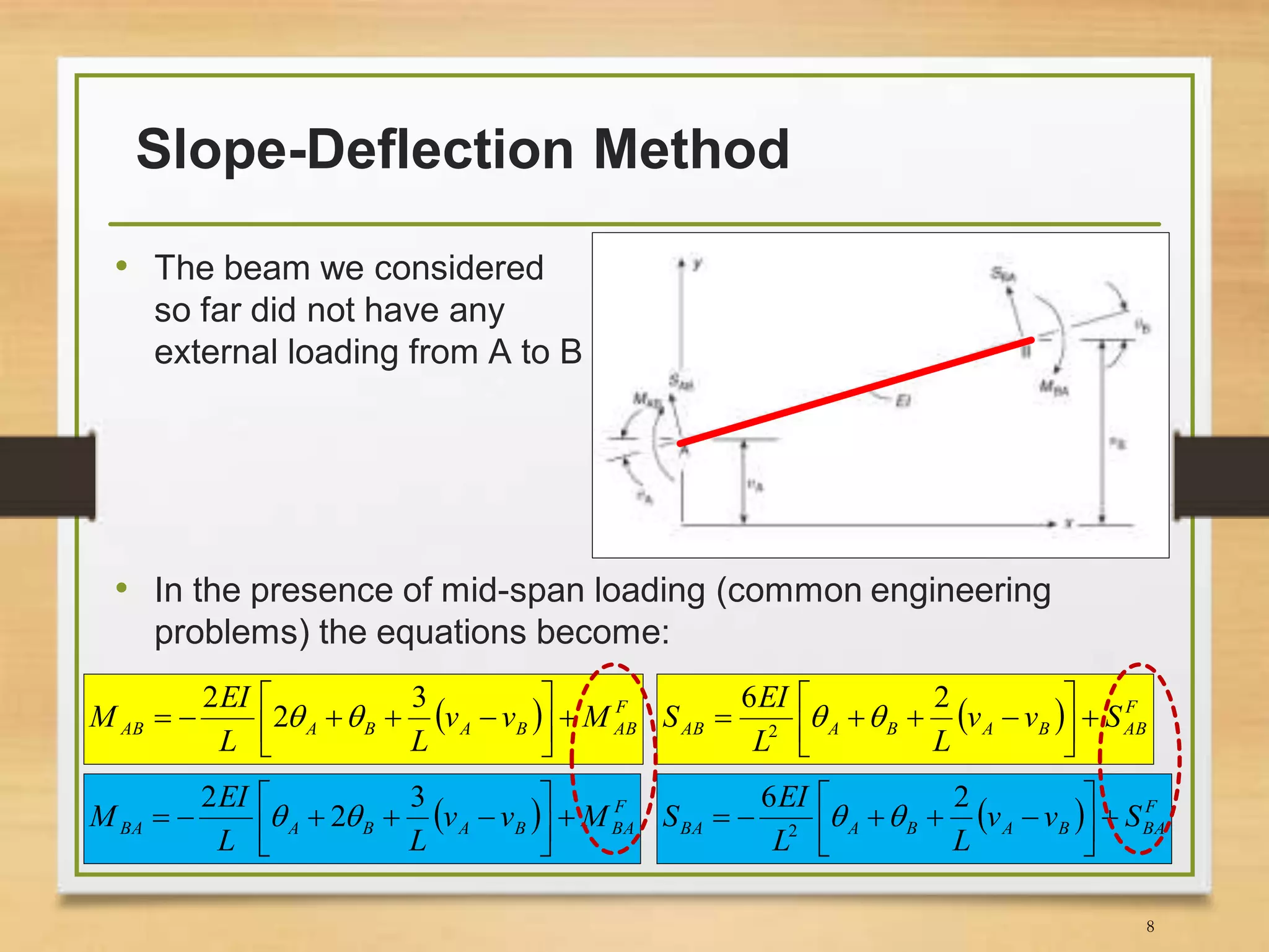

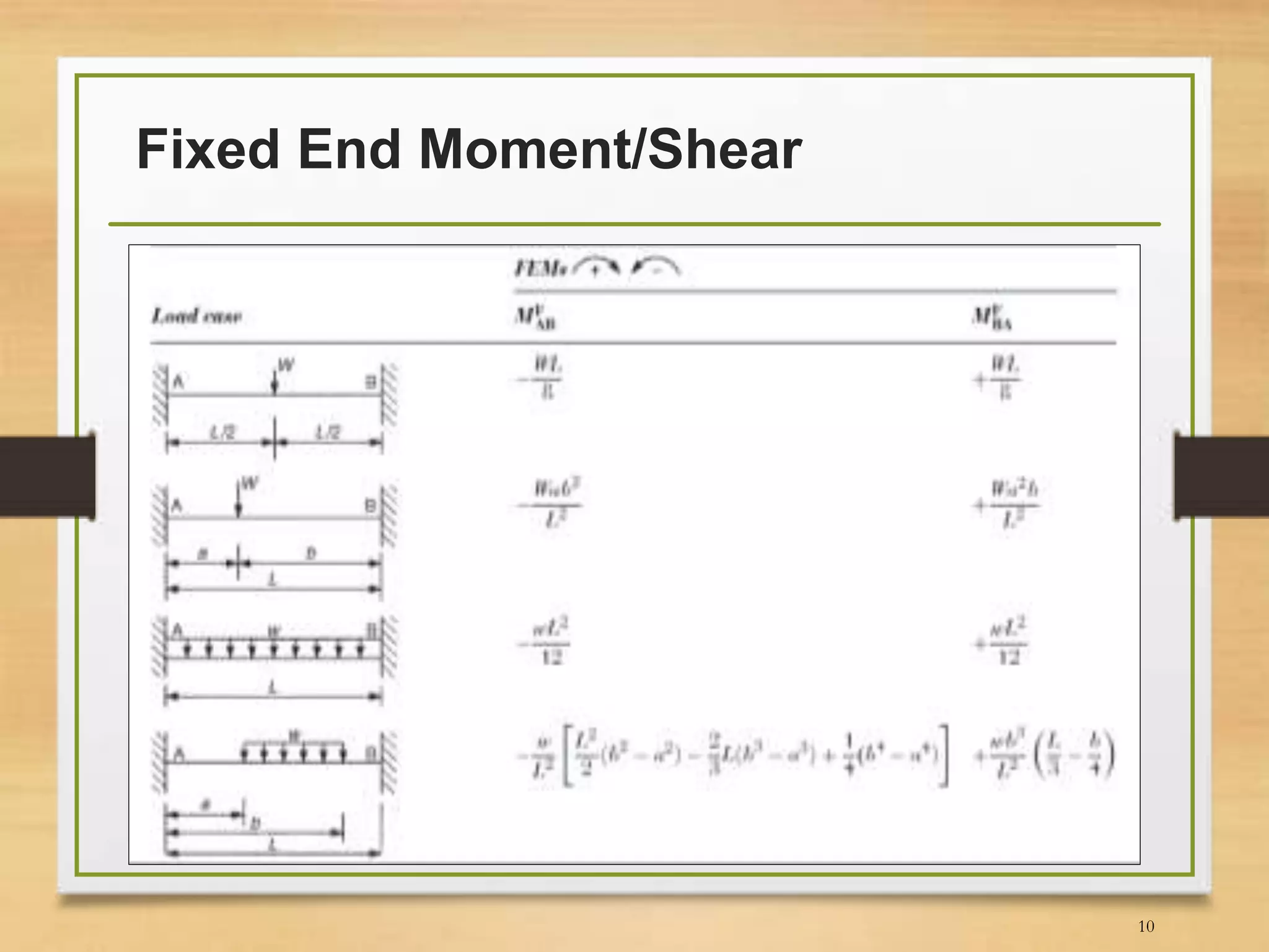
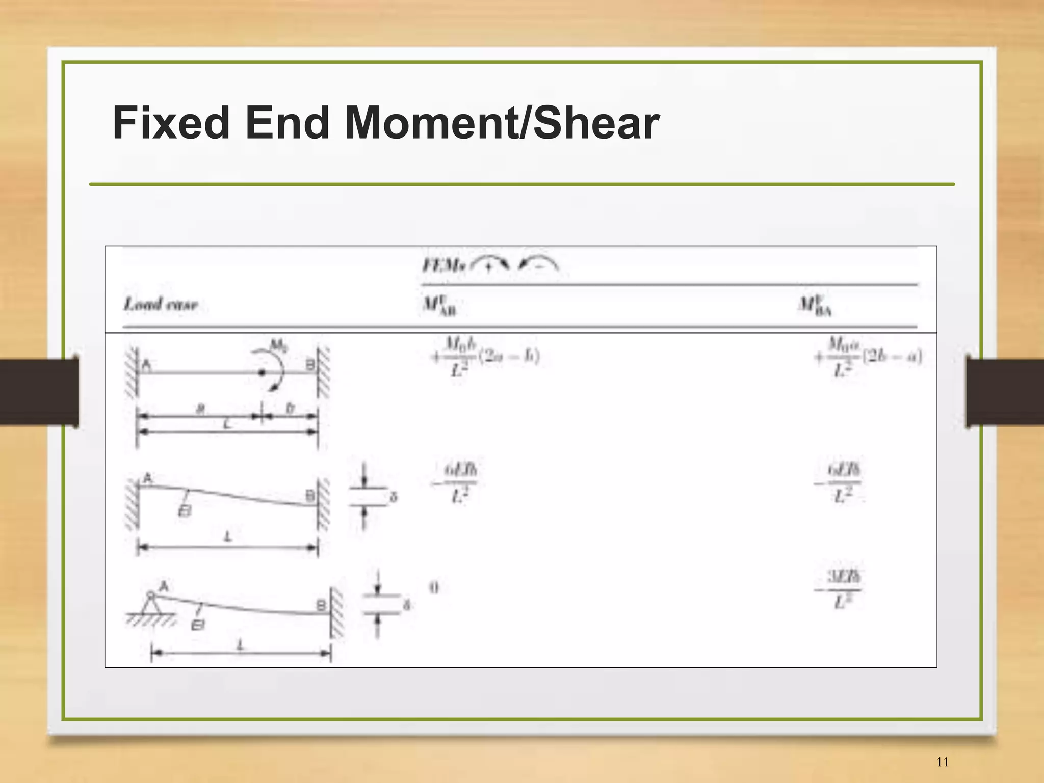
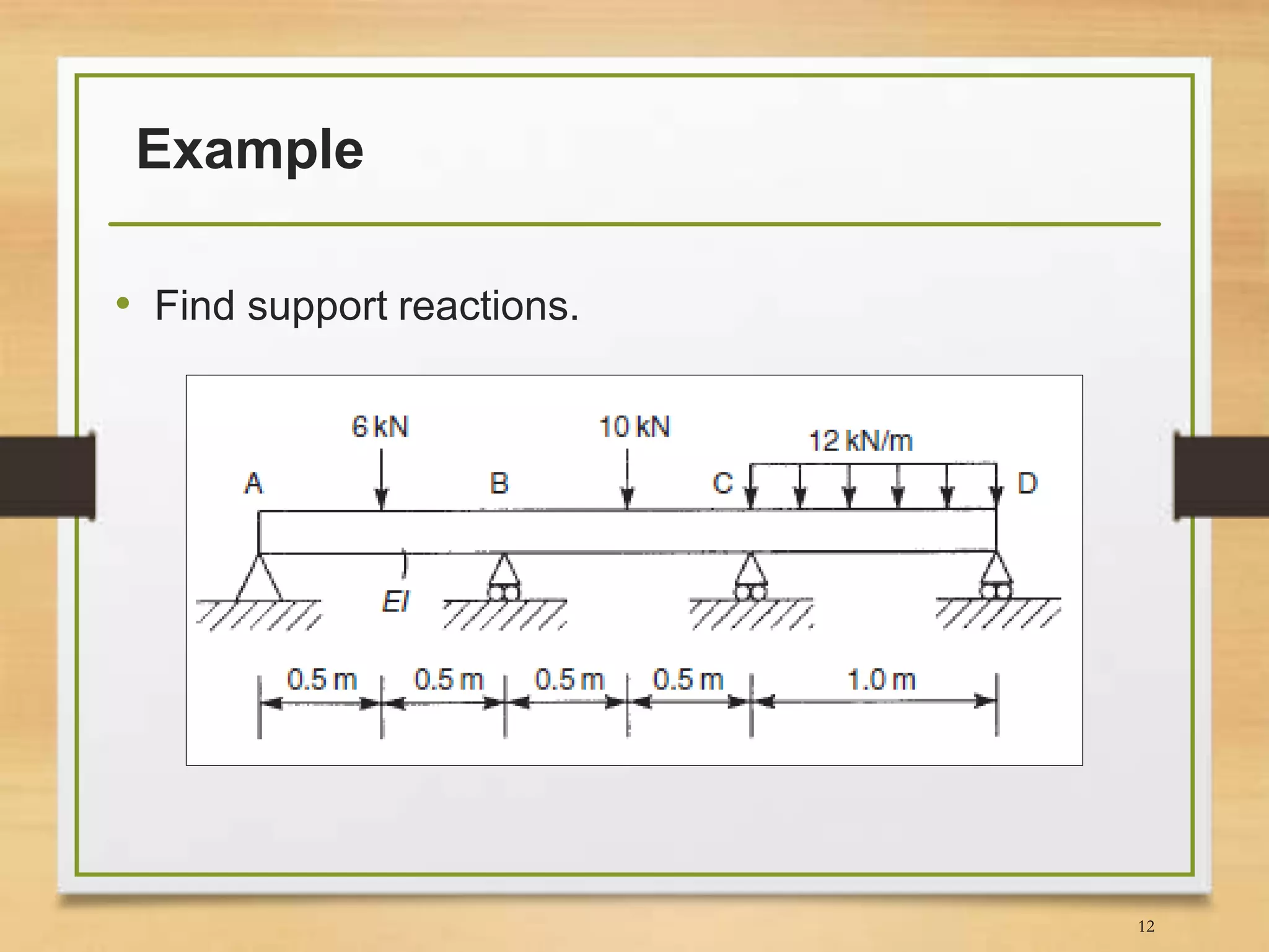
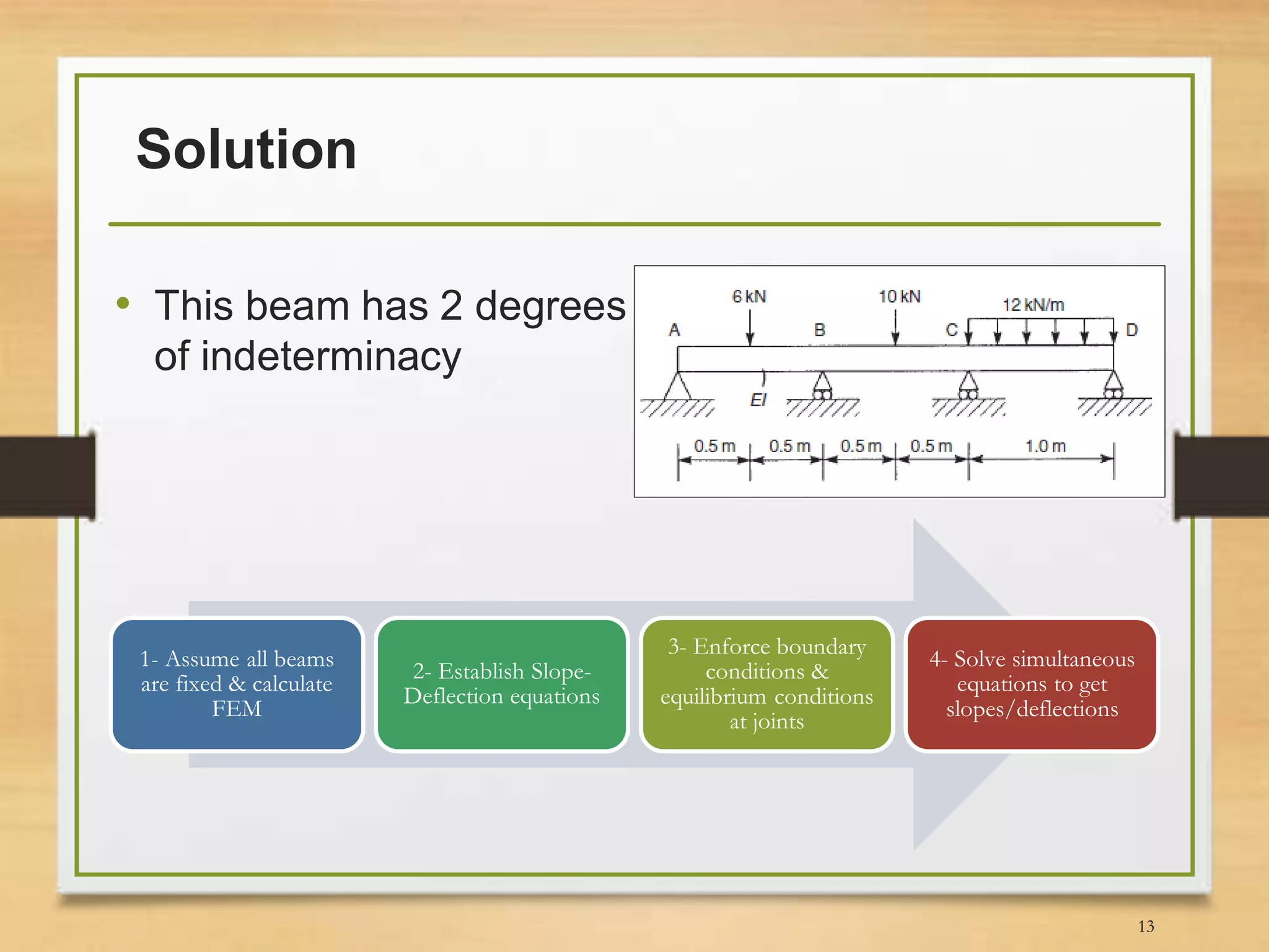
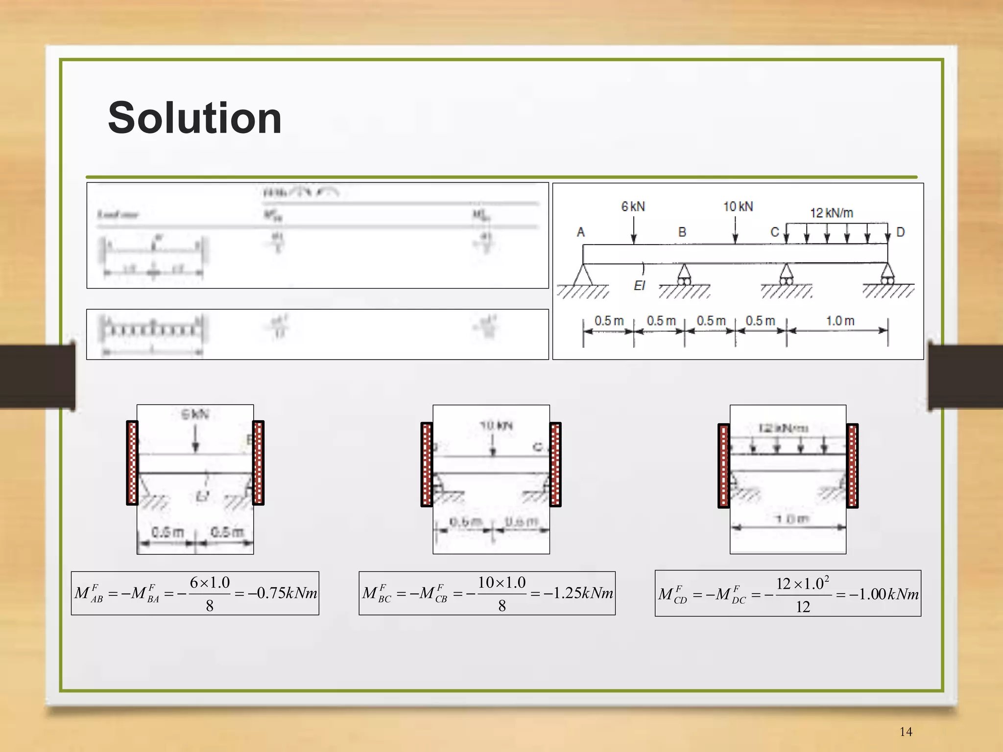

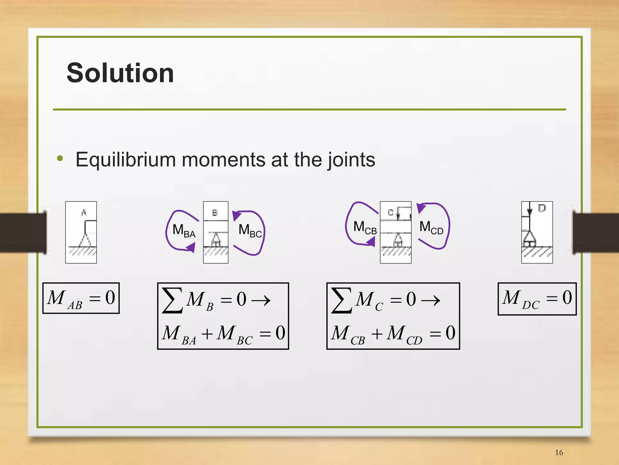
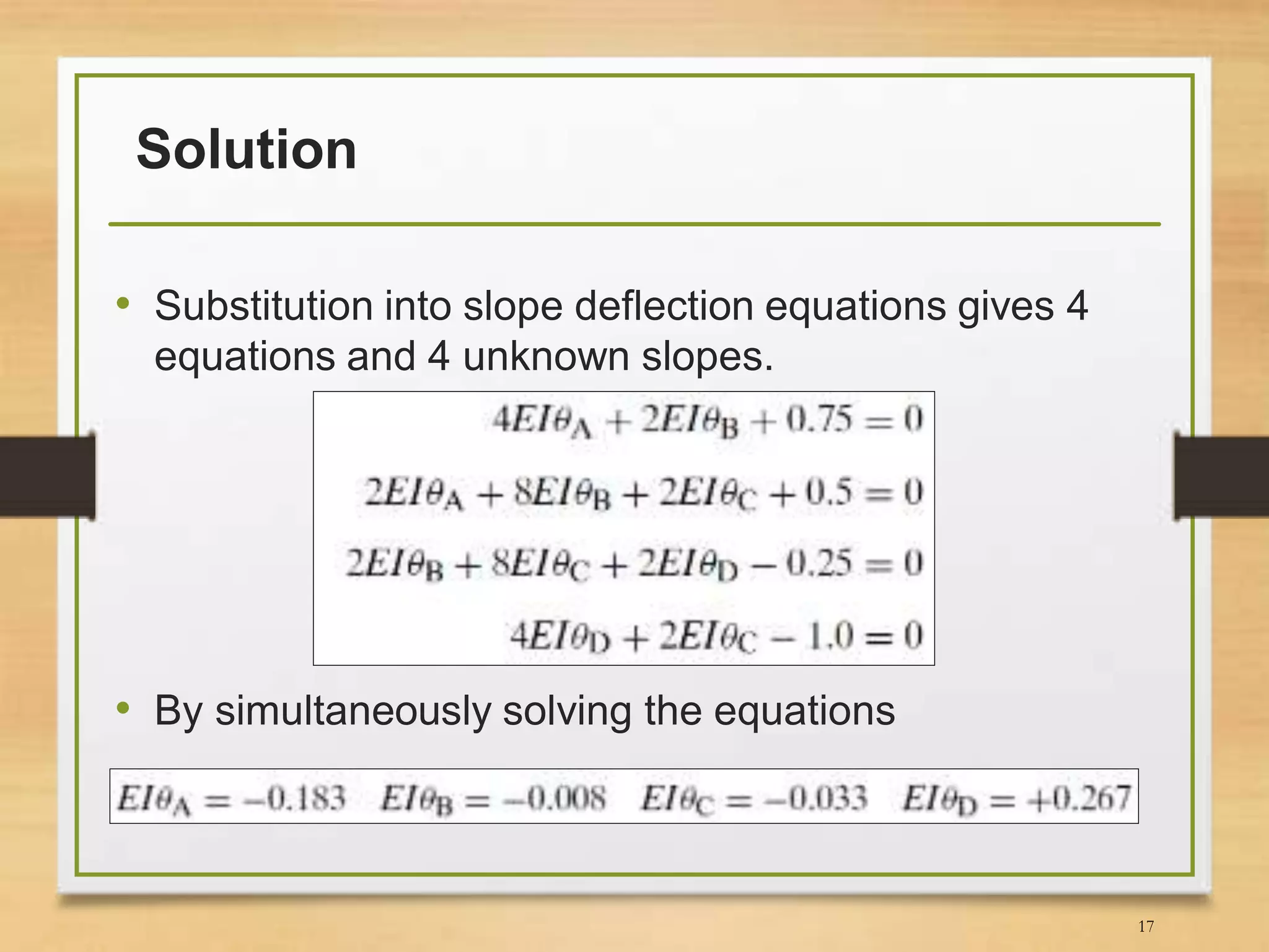
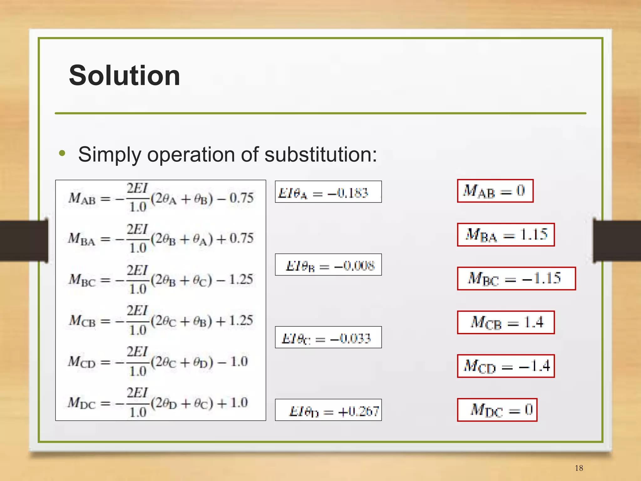


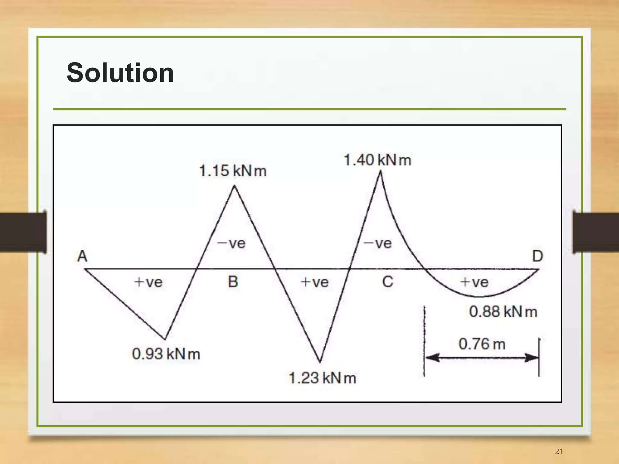
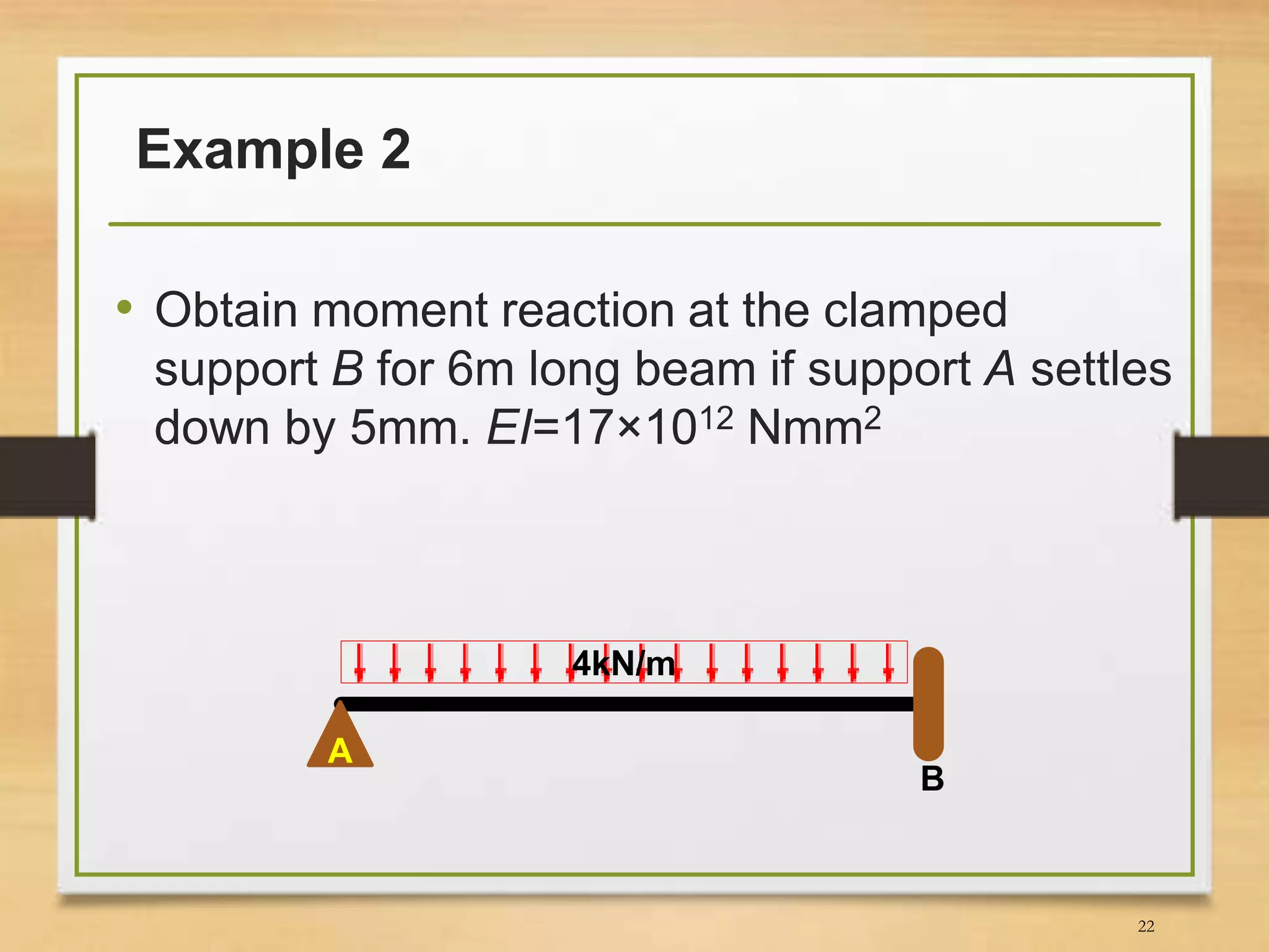


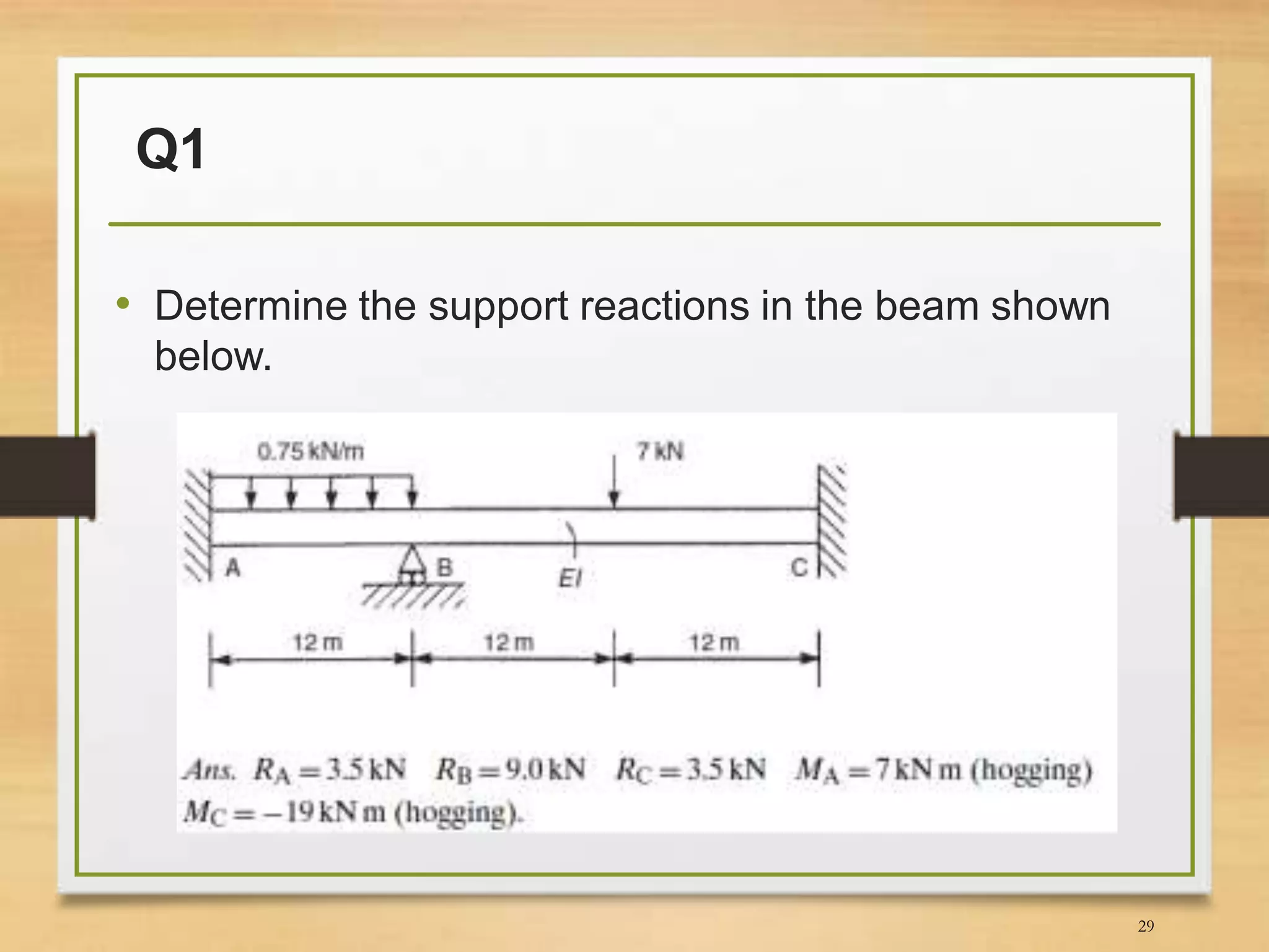
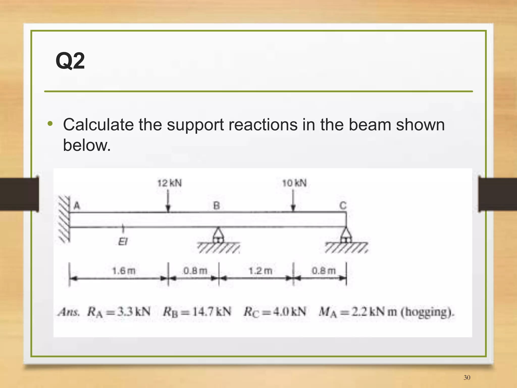

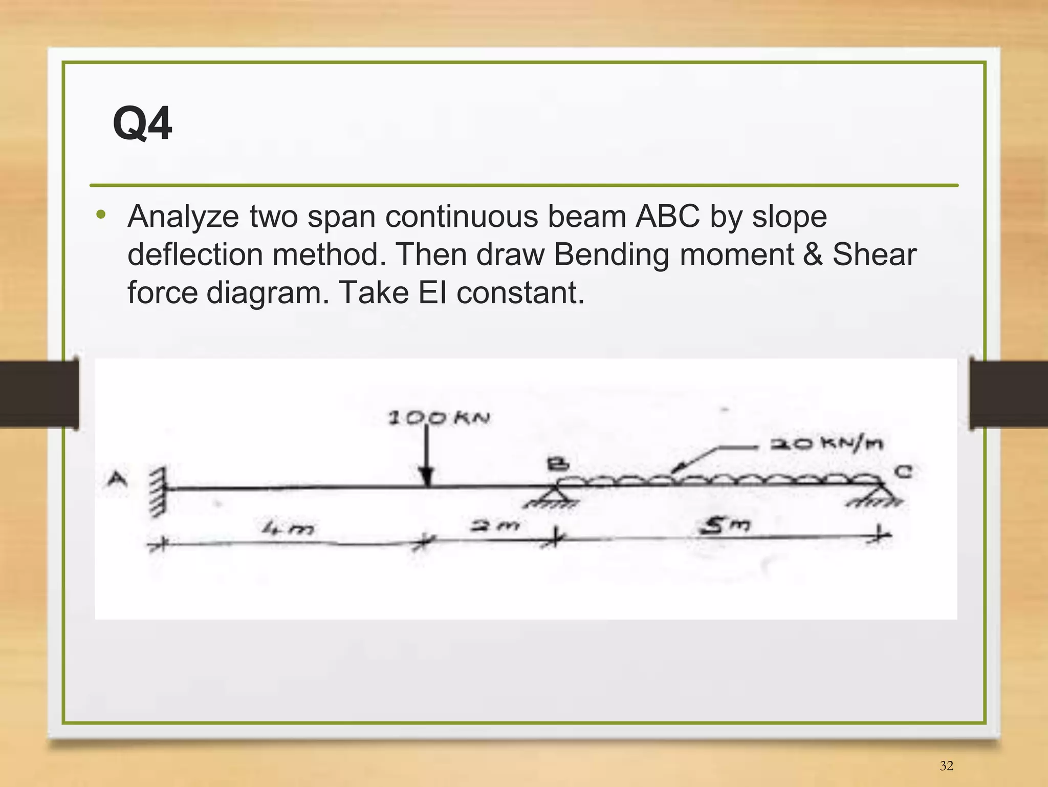

This document discusses the slope-deflection method for analyzing beams and frames. It provides the theory and equations of the slope-deflection method. Examples are included to demonstrate how to use the method to determine support reactions, member end moments, and draw bending moment and shear force diagrams.


![Geotechnical Engineering-II [Lec #25: Coulomb EP Theory - Numericals]](https://cdn.slidesharecdn.com/ss_thumbnails/25-181123050611-thumbnail.jpg?width=640&height=640&fit=bounds)


![MODULE-3.1[full].pdf](https://cdn.slidesharecdn.com/ss_thumbnails/module-3-220914062152-19974272-thumbnail.jpg?width=640&height=640&fit=bounds)


