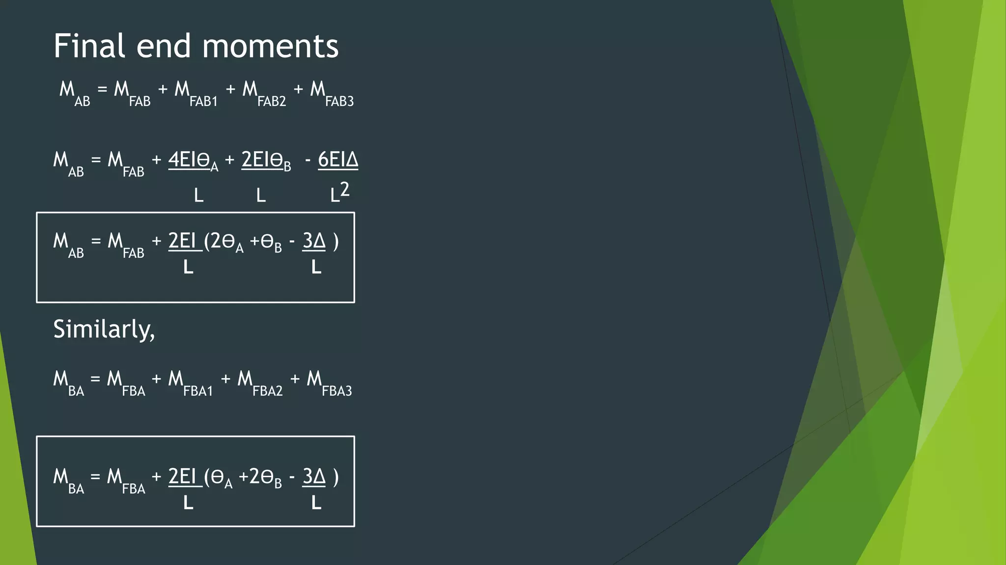
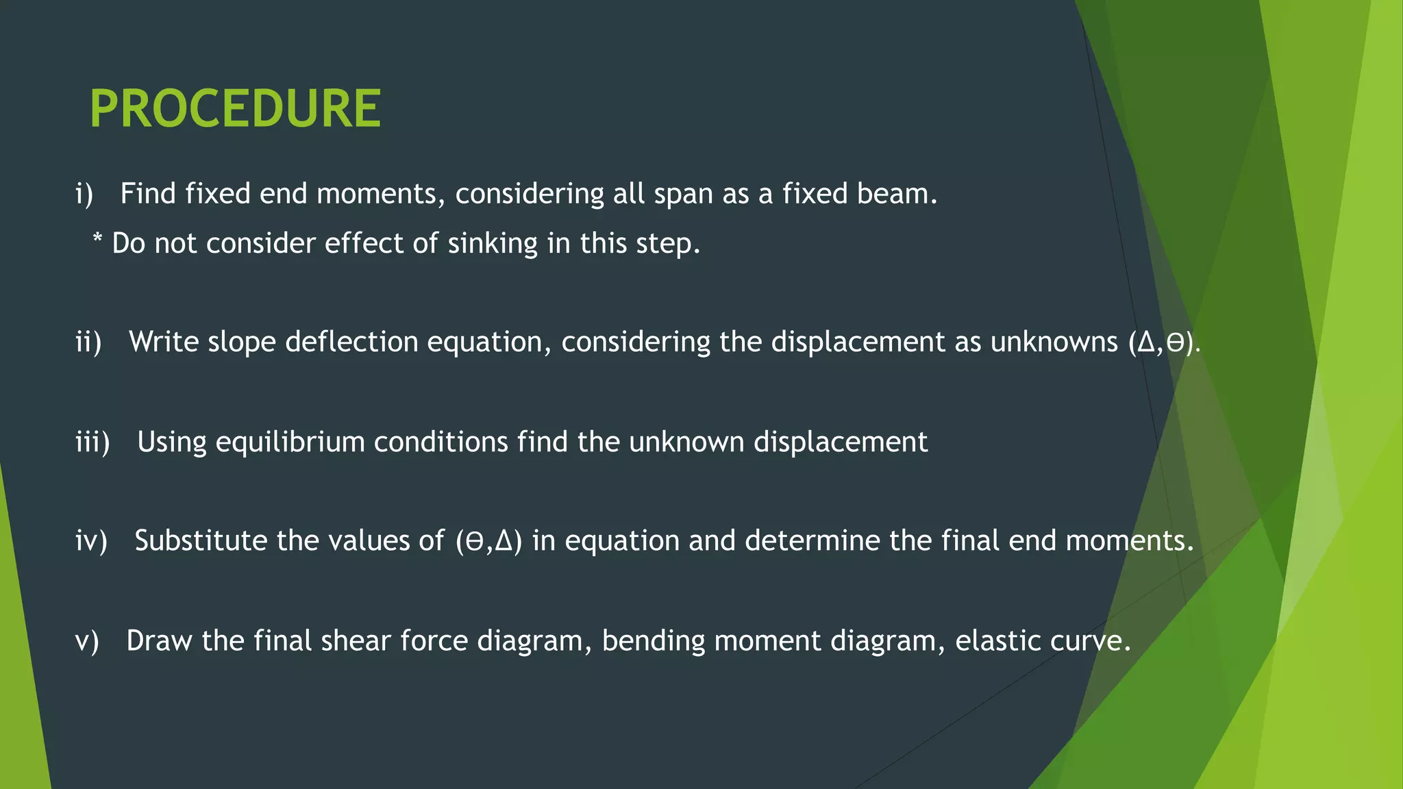
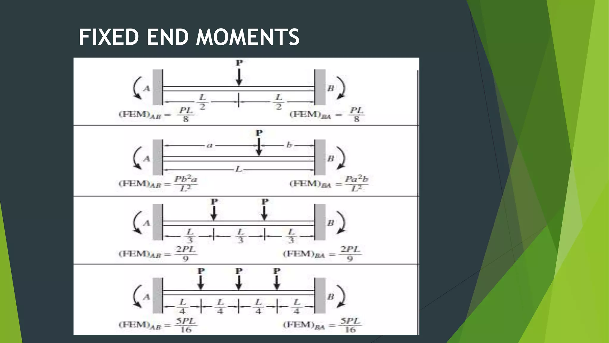
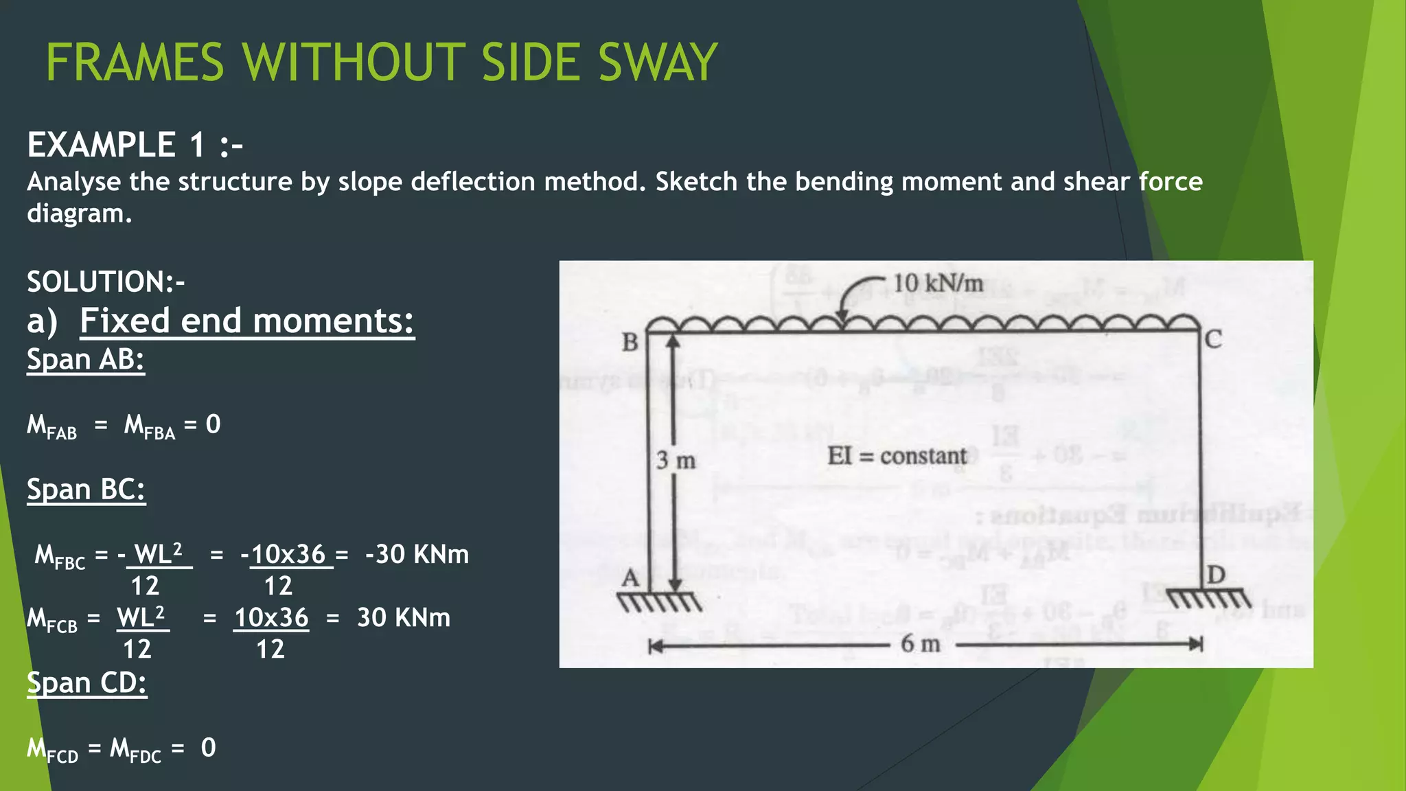
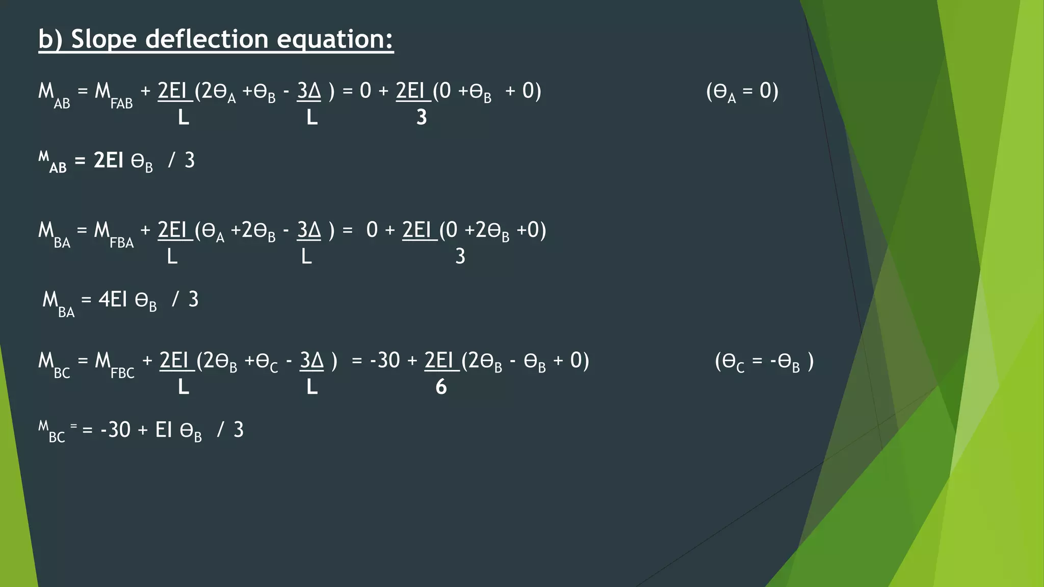
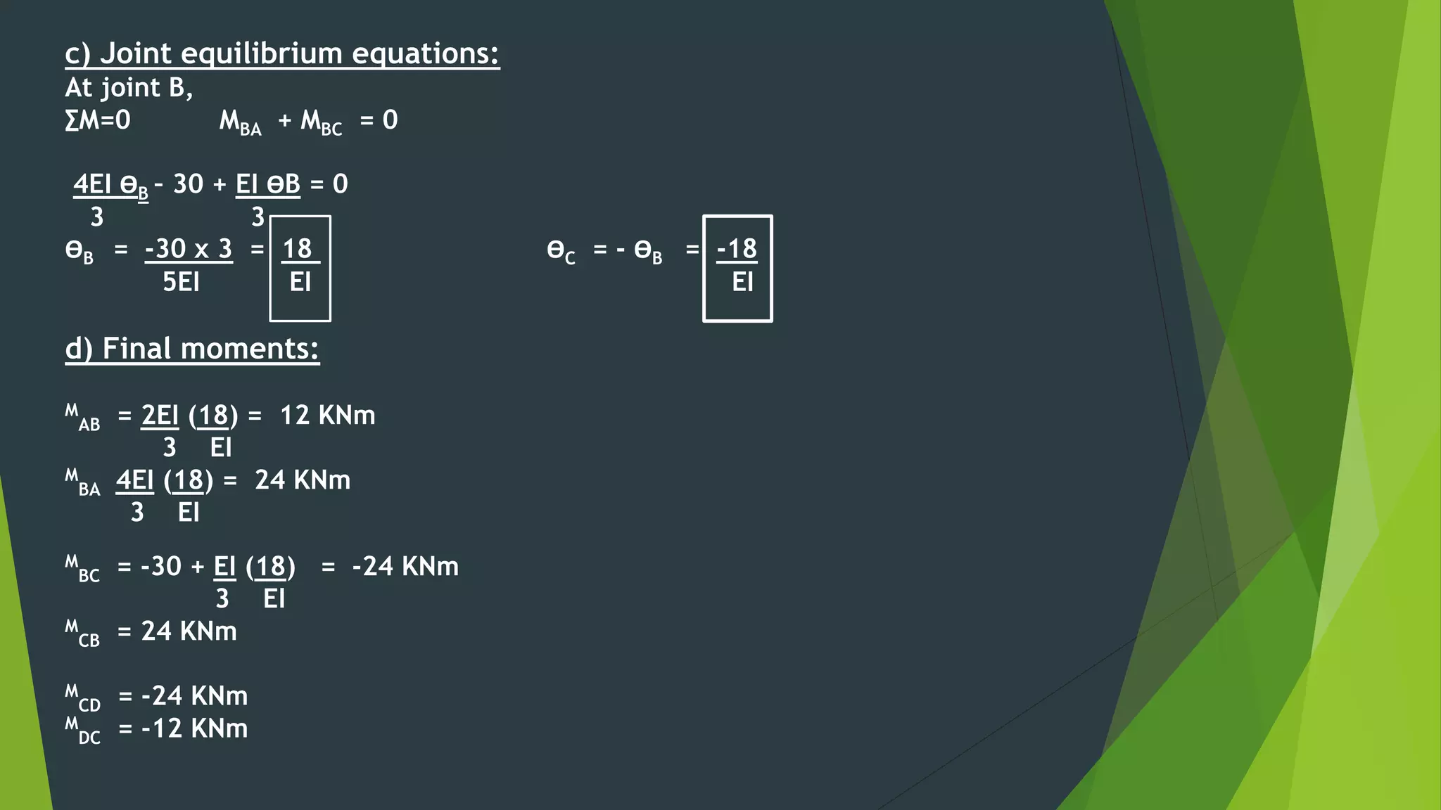
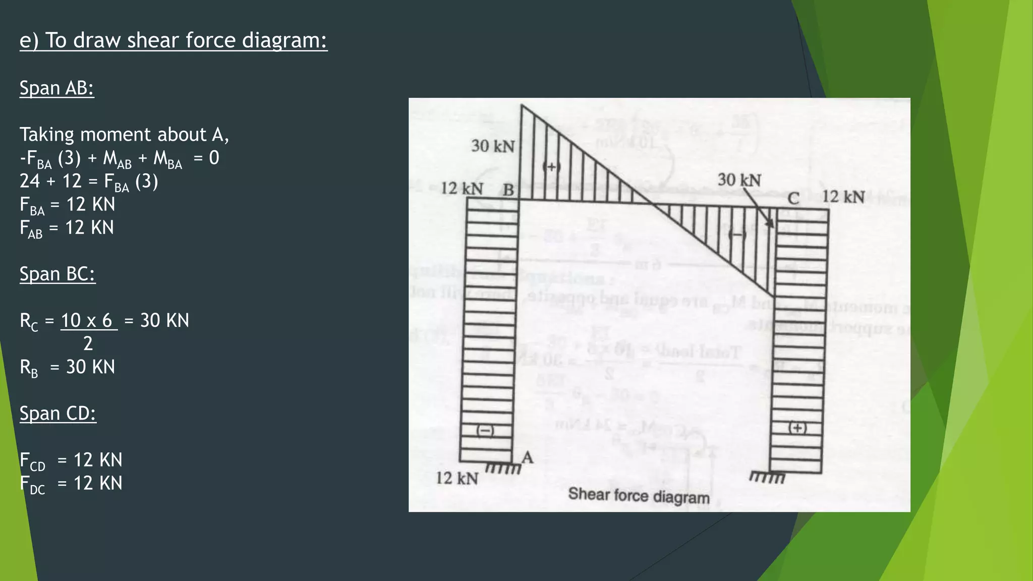
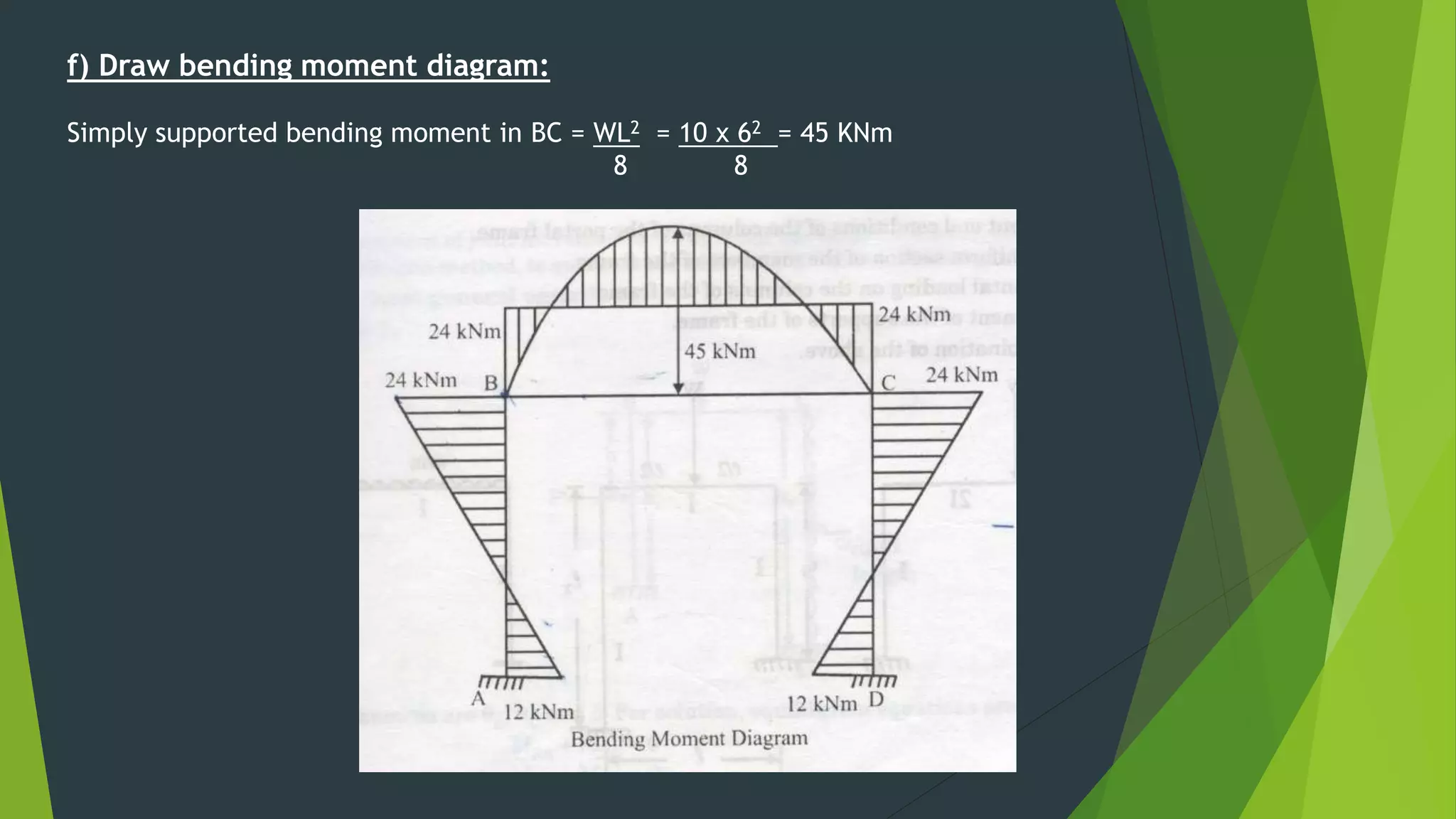
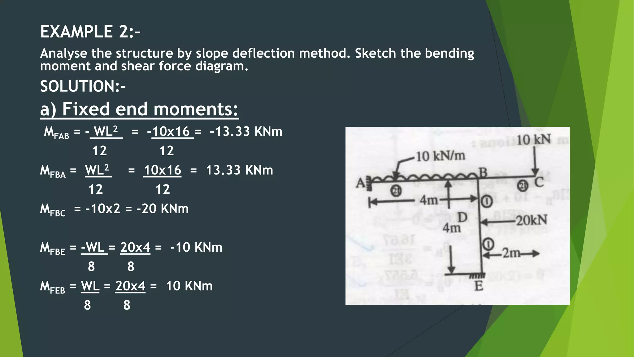
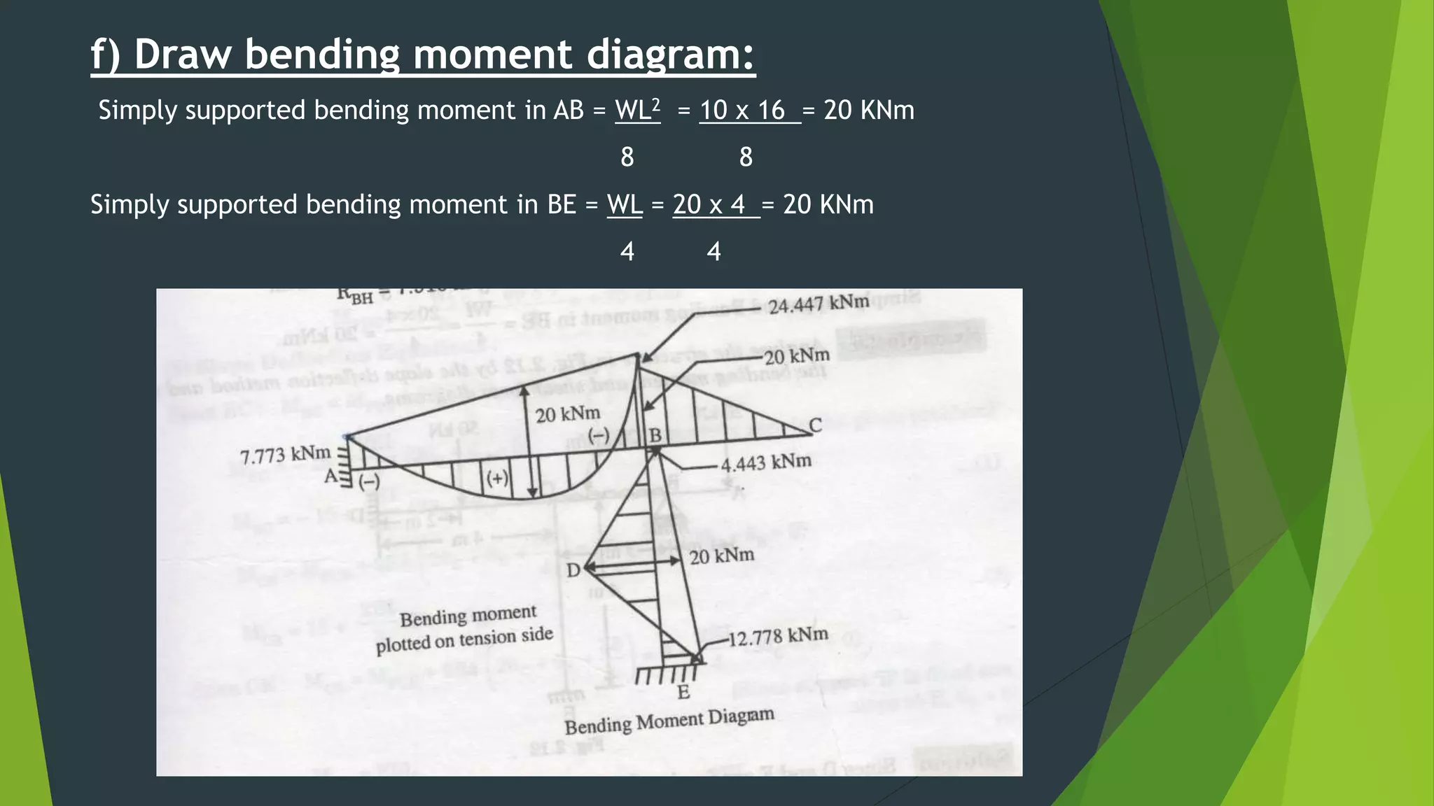
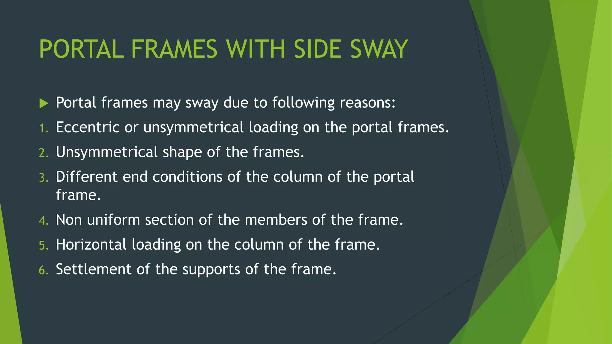
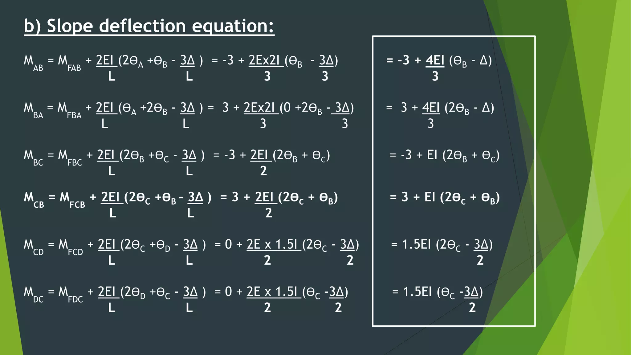
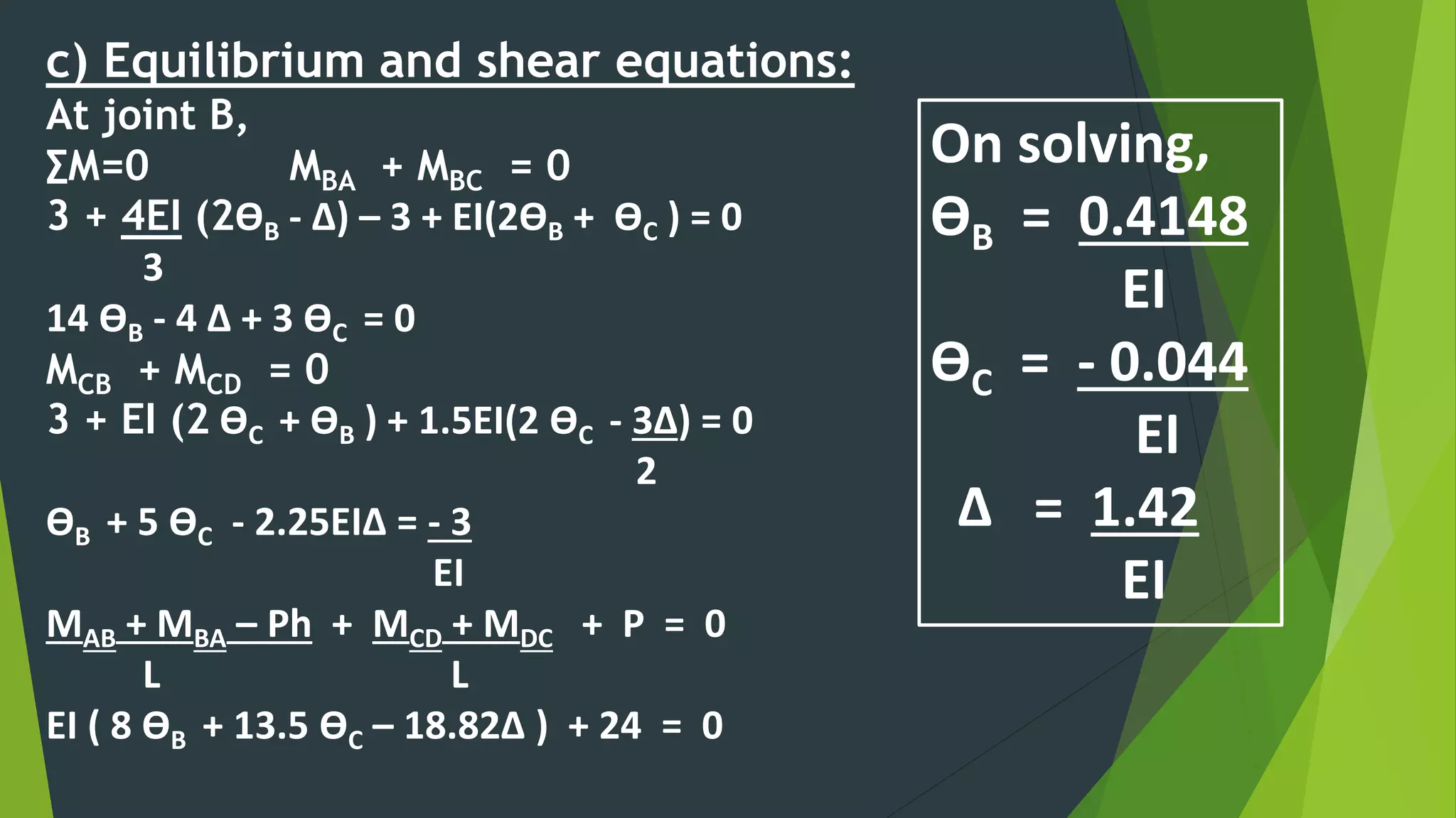
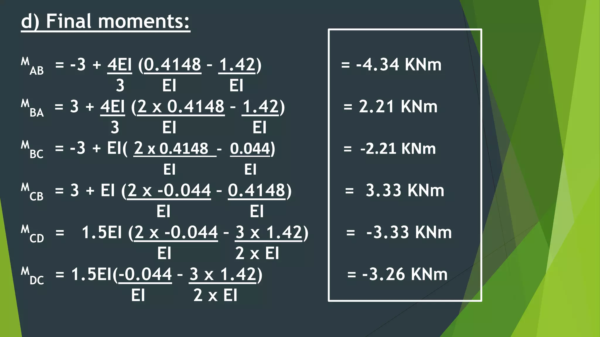
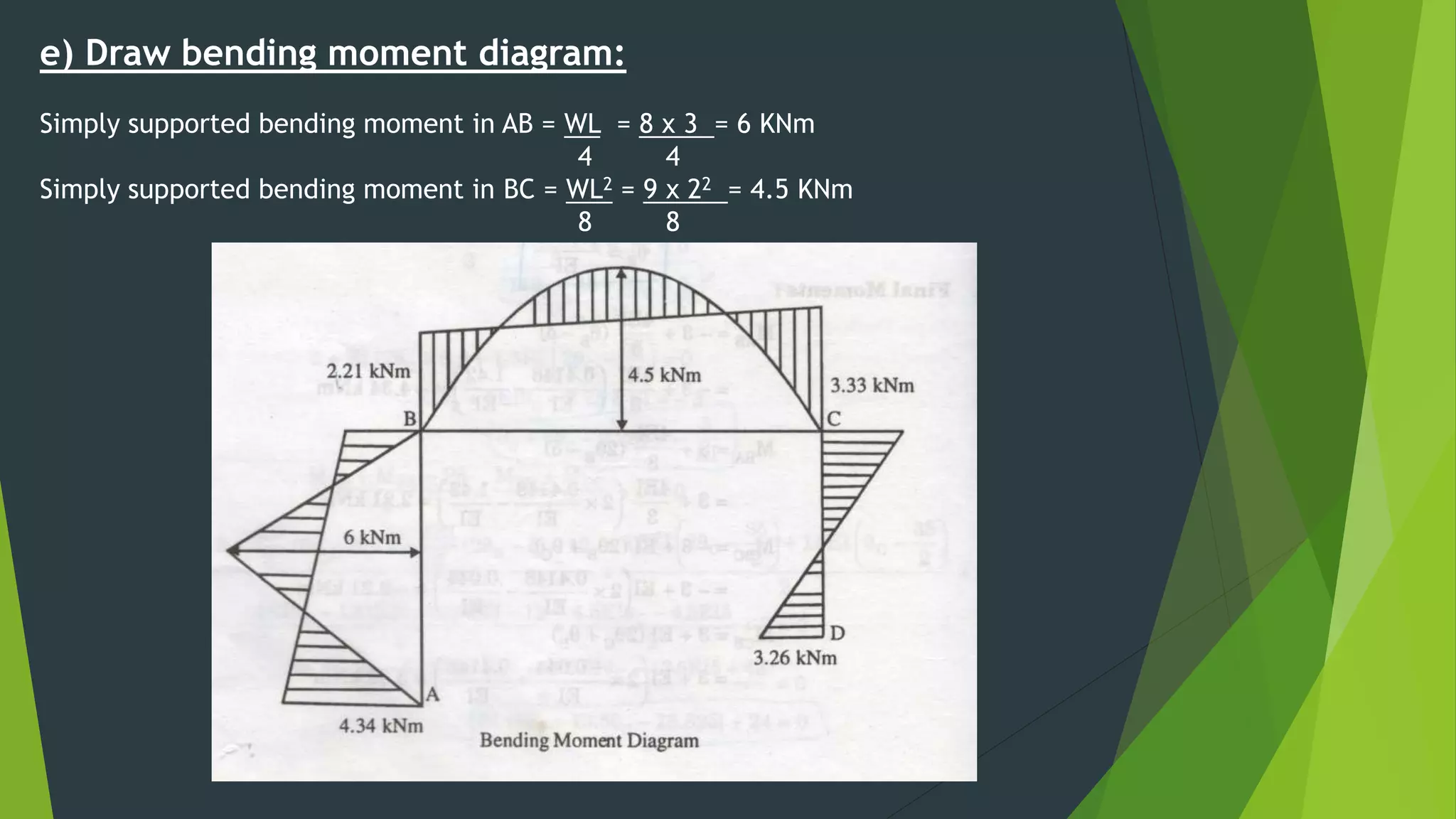
DEPARTMENT OF CIVIL ENGINEERING
SHIVALIK COLLEGE OF ENGINEERING
Dehradun, Uttrakhand, India, Email: info@sce.org.in, Website: www.sce.org.in
SLOPE DEFLECTION METHOD
ON PORTAL FRAMES
NAME – ASHU KUMAR KUSHWAHA
ROLL NO – 180410107004
BRANCH – B.TECH 3RD YEAR (C.E)
FACULTY NAME – DR.SUJEET KUMAR
DESIGNATION - RISP
INTRODUCTION
This method was developed by G.A Maney in
Germany in 1914. This method is applicable to
all types of statically indeterminate beams &
frames and in this method, we solve for
unknown joint rotations, which are expressed in
terms of the applied loads and the bending
moments. Deflections due to shear and axial
stresses are not considered as the effect are
small.
In slope deflection method, we shall find out the relation
between moments and slope at the joints. Then total
rotation due to applied loads and settlement of supports
may be found out and then by using the relations between
moments and slopes the net moments induced at the joint
may be found out.
a) The beam is having a constant section between each
pair of supports.
b) The joint in a structure as whole, may rotate or deflect,
but the angles between members meeting at the joint
remain the same.
ASSUMPTIONS
This method is based on the following simplified
assumptions:
 All the joints of the frame are rigid.
 Distortion, due to axial and shear stresses, being
very small, are neglected.
APPLICATIONS
1. Continuous Beams
2. Frames without side sway
3. Frames with side sway
SIGN CONVENTION:–
(1) ROTATIONS:– Clockwise joint rotations are
considered as (+ve).
(2) END MOMENTS:– Clockwise end moments
are considered as (+ve).
(3) SETTLEMENT:- When leads to clockwise
rotation considered as (+ve).
DERIVATION
Considering a continuous beam where A,B are the intermediate supports,
the final end moments developed at support A,B (MAB,MBA) will be due to
effect of
i) Effect of loading
ii) Rotation of joint A
iii) Rotation of joint B
iv) Effect of settlement of support
A B
By using superposition theorem the final end moment will be the summation of all the effects.
i) Effect of loading
A B
ii) Rotation at A
A B
ӨA
MFAB
= - PL/8
MFBA
= PL/8
MFAB1
= 4EIӨA/L
MFBA1
= 2EI ӨA/L
P
L/2 L/2
iii) Rotation at B
A B
ӨB
iv) Support B sinks by ∆
A B
ӨA
∆
MFAB2
= 2EIӨB/L
MFBA2
= 4EIӨB/L
MFAB3
= -6EI∆/L2
MFBA3
= -6EI∆/L2
Final end moments
MAB
= MFAB
+ MFAB1
+ MFAB2
+ MFAB3
MAB
= MFAB
+ 4EIӨA + 2EIӨB - 6EI∆
L L L2
MAB
= MFAB
+ 2EI (2ӨA +ӨB - 3∆ )
L L
Similarly,
MBA
= MFBA
+ MFBA1
+ MFBA2
+ MFBA3
MBA
= MFBA
+ 2EI (ӨA +2ӨB - 3∆ )
L L
PROCEDURE
i) Find fixed end moments, considering all span as a fixed beam.
* Do not consider effect of sinking in this step.
ii) Write slope deflection equation, considering the displacement as unknowns (∆,Ө).
iii) Using equilibrium conditions find the unknown displacement
iv) Substitute the values of (Ө,∆) in equation and determine the final end moments.
v) Draw the final shear force diagram, bending moment diagram, elastic curve.
FIXED END MOMENTS
EXAMPLE 1 :–
Analyse the structure by slope deflection method. Sketch the bending moment and shear force
diagram.
SOLUTION:-
a) Fixed end moments:
Span AB:
MFAB = MFBA = 0
Span BC:
MFBC = - WL2 = -10x36 = -30 KNm
12 12
MFCB = WL2 = 10x36 = 30 KNm
12 12
Span CD:
MFCD = MFDC = 0
FRAMES WITHOUT SIDE SWAY
b) Slope deflection equation:
MAB
= MFAB
+ 2EI (2ӨA +ӨB - 3∆ ) = 0 + 2EI (0 +ӨB + 0) (ӨA = 0)
L L 3
M
AB = 2EI ӨB / 3
MBA
= MFBA
+ 2EI (ӨA +2ӨB - 3∆ ) = 0 + 2EI (0 +2ӨB +0)
L L 3
MBA
= 4EI ӨB / 3
MBC
= MFBC
+ 2EI (2ӨB +ӨC - 3∆ ) = -30 + 2EI (2ӨB - ӨB + 0) (ӨC = -ӨB )
L L 6
M
BC
= = -30 + EI ӨB / 3
c) Joint equilibrium equations:
At joint B,
∑M=0 MBA + MBC = 0
4EI ӨB – 30 + EI ӨB = 0
3 3
ӨB = -30 x 3 = 18 ӨC = - ӨB = -18
5EI EI EI
d) Final moments:
M
AB = 2EI (18) = 12 KNm
3 EI
M
BA 4EI (18) = 24 KNm
3 EI
M
BC = -30 + EI (18) = -24 KNm
3 EI
M
CB = 24 KNm
M
CD = -24 KNm
M
DC = -12 KNm
e) To draw shear force diagram:
Span AB:
Taking moment about A,
-FBA (3) + MAB + MBA = 0
24 + 12 = FBA (3)
FBA = 12 KN
FAB = 12 KN
Span BC:
RC = 10 x 6 = 30 KN
2
RB = 30 KN
Span CD:
FCD = 12 KN
FDC = 12 KN
f) Draw bending moment diagram:
Simply supported bending moment in BC = WL2 = 10 x 62 = 45 KNm
8 8
EXAMPLE 2:–
Analyse the structure by slope deflection method. Sketch the bending
moment and shear force diagram.
SOLUTION:-
a) Fixed end moments:
MFAB = - WL2 = -10x16 = -13.33 KNm
12 12
MFBA = WL2 = 10x16 = 13.33 KNm
12 12
MFBC = -10x2 = -20 KNm
MFBE = -WL = 20x4 = -10 KNm
8 8
MFEB = WL = 20x4 = 10 KNm
8 8
b) Slope deflection equation:
MAB
= MFAB
+ 2EI (2ӨA +ӨB - 3∆ ) = -13.33 + 2Ex2I (0 +ӨB + 0)
L L 4
M
AB = -13.33 + EI ӨB
MBA
= MFBA
+ 2EI (ӨA +2ӨB - 3∆ ) = 13.33 + 2Ex2I (0 +2ӨB +0)
L L 4
MBA
= 13.33 + 2EI ӨB
MBE
= MFBE
+ 2EI (2ӨB +ӨE - 3∆ ) = -10 + 2EI (2ӨB +0 + 0)
L L 4
M
BE = -10 + EI ӨB
MEB
= MFEB
+ 2EI (2ӨE +ӨB - 3∆ ) = 10 + 2EI (0 + ӨB + 0)
L L 4
M
BE
= = 10 + 0.5EI ӨB
c) Joint equilibrium equations:
At joint B,
∑M=0 MBA + MBC + MBE = 0
13.33 + 2EI ӨB – 10 + EIӨB -20 = 0
3EI ӨB – 16.67 = 0
ӨB = 16.67 ӨC = 5.557
3EIӨC EI
d) Final moments:
M
AB = -13.33 + EI (5.557) = -7.773 KNm
EI
M
BA = 13.33 + 2EI (5.557) = 24.447 KNm
EI
M
BC = -20 KNm
M
BE = -10 + EI (5.557) = -4.443 KNm
EI
M
EB = 10 + EI (5.557) = 12.778 KNm
2 EI
e) To draw shear force diagram:
Span AB:
taking moment about B,
RA x 4 – 10 x 4(4/2) - 7.773 + 24.447 = 0
RA = 15.832 KN
RB1 = 10 x 4 – RA = 24.168 KN
Span BE:
Taking moment about B,
-RE (4) – 4.443 + 12.778 + 20(2) = 0
RE = 12.084 KN
RB2 = total load – RE = 7.916 KN
f) Draw bending moment diagram:
Simply supported bending moment in AB = WL2 = 10 x 16 = 20 KNm
8 8
Simply supported bending moment in BE = WL = 20 x 4 = 20 KNm
4 4
PORTAL FRAMES WITH SIDE SWAY
 Portal frames may sway due to following reasons:
1. Eccentric or unsymmetrical loading on the portal frames.
2. Unsymmetrical shape of the frames.
3. Different end conditions of the column of the portal
frame.
4. Non uniform section of the members of the frame.
5. Horizontal loading on the column of the frame.
6. Settlement of the supports of the frame.
EXAMPLE 3 :–
Analyse the frame by slope deflection method and draw the bending moment diagram.
SOLUTION:-
a) Fixed end moments:
MFAB = -WL = -8 x 3 = -3 KNm
8 8
MFBA = WL = 8 x 3 = 3 KNm
8 8
MFBC = - WL2 = -9x22 = -3 KNm
12 12
MFCB = WL2 = 9x22 = 3 KNm
12 12
MFCD = MFDC = 0
b) Slope deflection equation:
MAB
= MFAB
+ 2EI (2ӨA +ӨB - 3∆ ) = -3 + 2Ex2I (ӨB - 3∆) = -3 + 4EI (ӨB - ∆)
L L 3 3 3
MBA
= MFBA
+ 2EI (ӨA +2ӨB - 3∆ ) = 3 + 2Ex2I (0 +2ӨB - 3∆) = 3 + 4EI (2ӨB - ∆)
L L 3 3 3
MBC
= MFBC
+ 2EI (2ӨB +ӨC - 3∆ ) = -3 + 2EI (2ӨB + ӨC) = -3 + EI (2ӨB + ӨC)
L L 2
MCB
= MFCB
+ 2EI (2ӨC +ӨB - 3∆ ) = 3 + 2EI (2ӨC + ӨB) = 3 + EI (2ӨC + ӨB)
L L 2
MCD
= MFCD
+ 2EI (2ӨC +ӨD - 3∆ ) = 0 + 2E x 1.5I (2ӨC - 3∆) = 1.5EI (2ӨC - 3∆)
L L 2 2 2
MDC
= MFDC
+ 2EI (2ӨD +ӨC - 3∆ ) = 0 + 2E x 1.5I (ӨC -3∆) = 1.5EI (ӨC -3∆)
L L 2 2 2
c) Equilibrium and shear equations:
At joint B,
∑M=0 MBA + MBC = 0
3 + 4EI (2ӨB - ∆) – 3 + EI(2ӨB + ӨC ) = 0
3
14 ӨB - 4 ∆ + 3 ӨC = 0
MCB + MCD = 0
3 + EI (2 ӨC + ӨB ) + 1.5EI(2 ӨC - 3∆) = 0
2
ӨB + 5 ӨC - 2.25EI∆ = - 3
EI
MAB + MBA – Ph + MCD + MDC + P = 0
L L
EI ( 8 ӨB + 13.5 ӨC – 18.82∆ ) + 24 = 0
On solving,
ӨB = 0.4148
EI
ӨC = - 0.044
EI
∆ = 1.42
EI
d) Final moments:
M
AB = -3 + 4EI (0.4148 – 1.42) = -4.34 KNm
3 EI EI
M
BA = 3 + 4EI (2 x 0.4148 – 1.42) = 2.21 KNm
3 EI EI
M
BC = -3 + EI( 2 x 0.4148 - 0.044) = -2.21 KNm
EI EI
M
CB = 3 + EI (2 x -0.044 – 0.4148) = 3.33 KNm
EI EI
M
CD = 1.5EI (2 x -0.044 – 3 x 1.42) = -3.33 KNm
EI 2 x EI
M
DC = 1.5EI(-0.044 – 3 x 1.42) = -3.26 KNm
EI 2 x EI
e) Draw bending moment diagram:
Simply supported bending moment in AB = WL = 8 x 3 = 6 KNm
4 4
Simply supported bending moment in BC = WL2 = 9 x 22 = 4.5 KNm
8 8
THANK
YOU

Slope deflection equation structure analysis - civil engineering

  • 1.
    DEPARTMENT OF CIVILENGINEERING SHIVALIK COLLEGE OF ENGINEERING Dehradun, Uttrakhand, India, Email: info@sce.org.in, Website: www.sce.org.in SLOPE DEFLECTION METHOD ON PORTAL FRAMES NAME – ASHU KUMAR KUSHWAHA ROLL NO – 180410107004 BRANCH – B.TECH 3RD YEAR (C.E) FACULTY NAME – DR.SUJEET KUMAR DESIGNATION - RISP
  • 2.
    INTRODUCTION This method wasdeveloped by G.A Maney in Germany in 1914. This method is applicable to all types of statically indeterminate beams & frames and in this method, we solve for unknown joint rotations, which are expressed in terms of the applied loads and the bending moments. Deflections due to shear and axial stresses are not considered as the effect are small.
  • 3.
    In slope deflectionmethod, we shall find out the relation between moments and slope at the joints. Then total rotation due to applied loads and settlement of supports may be found out and then by using the relations between moments and slopes the net moments induced at the joint may be found out. a) The beam is having a constant section between each pair of supports. b) The joint in a structure as whole, may rotate or deflect, but the angles between members meeting at the joint remain the same.
  • 4.
    ASSUMPTIONS This method isbased on the following simplified assumptions:  All the joints of the frame are rigid.  Distortion, due to axial and shear stresses, being very small, are neglected.
  • 5.
    APPLICATIONS 1. Continuous Beams 2.Frames without side sway 3. Frames with side sway
  • 6.
    SIGN CONVENTION:– (1) ROTATIONS:–Clockwise joint rotations are considered as (+ve). (2) END MOMENTS:– Clockwise end moments are considered as (+ve). (3) SETTLEMENT:- When leads to clockwise rotation considered as (+ve).
  • 7.
    DERIVATION Considering a continuousbeam where A,B are the intermediate supports, the final end moments developed at support A,B (MAB,MBA) will be due to effect of i) Effect of loading ii) Rotation of joint A iii) Rotation of joint B iv) Effect of settlement of support A B
  • 8.
    By using superpositiontheorem the final end moment will be the summation of all the effects. i) Effect of loading A B ii) Rotation at A A B ӨA MFAB = - PL/8 MFBA = PL/8 MFAB1 = 4EIӨA/L MFBA1 = 2EI ӨA/L P L/2 L/2
  • 9.
    iii) Rotation atB A B ӨB iv) Support B sinks by ∆ A B ӨA ∆ MFAB2 = 2EIӨB/L MFBA2 = 4EIӨB/L MFAB3 = -6EI∆/L2 MFBA3 = -6EI∆/L2
  • 10.
    Final end moments MAB =MFAB + MFAB1 + MFAB2 + MFAB3 MAB = MFAB + 4EIӨA + 2EIӨB - 6EI∆ L L L2 MAB = MFAB + 2EI (2ӨA +ӨB - 3∆ ) L L Similarly, MBA = MFBA + MFBA1 + MFBA2 + MFBA3 MBA = MFBA + 2EI (ӨA +2ӨB - 3∆ ) L L
  • 11.
    PROCEDURE i) Find fixedend moments, considering all span as a fixed beam. * Do not consider effect of sinking in this step. ii) Write slope deflection equation, considering the displacement as unknowns (∆,Ө). iii) Using equilibrium conditions find the unknown displacement iv) Substitute the values of (Ө,∆) in equation and determine the final end moments. v) Draw the final shear force diagram, bending moment diagram, elastic curve.
  • 12.
  • 14.
    EXAMPLE 1 :– Analysethe structure by slope deflection method. Sketch the bending moment and shear force diagram. SOLUTION:- a) Fixed end moments: Span AB: MFAB = MFBA = 0 Span BC: MFBC = - WL2 = -10x36 = -30 KNm 12 12 MFCB = WL2 = 10x36 = 30 KNm 12 12 Span CD: MFCD = MFDC = 0 FRAMES WITHOUT SIDE SWAY
  • 15.
    b) Slope deflectionequation: MAB = MFAB + 2EI (2ӨA +ӨB - 3∆ ) = 0 + 2EI (0 +ӨB + 0) (ӨA = 0) L L 3 M AB = 2EI ӨB / 3 MBA = MFBA + 2EI (ӨA +2ӨB - 3∆ ) = 0 + 2EI (0 +2ӨB +0) L L 3 MBA = 4EI ӨB / 3 MBC = MFBC + 2EI (2ӨB +ӨC - 3∆ ) = -30 + 2EI (2ӨB - ӨB + 0) (ӨC = -ӨB ) L L 6 M BC = = -30 + EI ӨB / 3
  • 16.
    c) Joint equilibriumequations: At joint B, ∑M=0 MBA + MBC = 0 4EI ӨB – 30 + EI ӨB = 0 3 3 ӨB = -30 x 3 = 18 ӨC = - ӨB = -18 5EI EI EI d) Final moments: M AB = 2EI (18) = 12 KNm 3 EI M BA 4EI (18) = 24 KNm 3 EI M BC = -30 + EI (18) = -24 KNm 3 EI M CB = 24 KNm M CD = -24 KNm M DC = -12 KNm
  • 17.
    e) To drawshear force diagram: Span AB: Taking moment about A, -FBA (3) + MAB + MBA = 0 24 + 12 = FBA (3) FBA = 12 KN FAB = 12 KN Span BC: RC = 10 x 6 = 30 KN 2 RB = 30 KN Span CD: FCD = 12 KN FDC = 12 KN
  • 18.
    f) Draw bendingmoment diagram: Simply supported bending moment in BC = WL2 = 10 x 62 = 45 KNm 8 8
  • 19.
    EXAMPLE 2:– Analyse thestructure by slope deflection method. Sketch the bending moment and shear force diagram. SOLUTION:- a) Fixed end moments: MFAB = - WL2 = -10x16 = -13.33 KNm 12 12 MFBA = WL2 = 10x16 = 13.33 KNm 12 12 MFBC = -10x2 = -20 KNm MFBE = -WL = 20x4 = -10 KNm 8 8 MFEB = WL = 20x4 = 10 KNm 8 8
  • 20.
    b) Slope deflectionequation: MAB = MFAB + 2EI (2ӨA +ӨB - 3∆ ) = -13.33 + 2Ex2I (0 +ӨB + 0) L L 4 M AB = -13.33 + EI ӨB MBA = MFBA + 2EI (ӨA +2ӨB - 3∆ ) = 13.33 + 2Ex2I (0 +2ӨB +0) L L 4 MBA = 13.33 + 2EI ӨB MBE = MFBE + 2EI (2ӨB +ӨE - 3∆ ) = -10 + 2EI (2ӨB +0 + 0) L L 4 M BE = -10 + EI ӨB MEB = MFEB + 2EI (2ӨE +ӨB - 3∆ ) = 10 + 2EI (0 + ӨB + 0) L L 4 M BE = = 10 + 0.5EI ӨB
  • 21.
    c) Joint equilibriumequations: At joint B, ∑M=0 MBA + MBC + MBE = 0 13.33 + 2EI ӨB – 10 + EIӨB -20 = 0 3EI ӨB – 16.67 = 0 ӨB = 16.67 ӨC = 5.557 3EIӨC EI d) Final moments: M AB = -13.33 + EI (5.557) = -7.773 KNm EI M BA = 13.33 + 2EI (5.557) = 24.447 KNm EI M BC = -20 KNm M BE = -10 + EI (5.557) = -4.443 KNm EI M EB = 10 + EI (5.557) = 12.778 KNm 2 EI
  • 22.
    e) To drawshear force diagram: Span AB: taking moment about B, RA x 4 – 10 x 4(4/2) - 7.773 + 24.447 = 0 RA = 15.832 KN RB1 = 10 x 4 – RA = 24.168 KN Span BE: Taking moment about B, -RE (4) – 4.443 + 12.778 + 20(2) = 0 RE = 12.084 KN RB2 = total load – RE = 7.916 KN
  • 23.
    f) Draw bendingmoment diagram: Simply supported bending moment in AB = WL2 = 10 x 16 = 20 KNm 8 8 Simply supported bending moment in BE = WL = 20 x 4 = 20 KNm 4 4
  • 24.
    PORTAL FRAMES WITHSIDE SWAY  Portal frames may sway due to following reasons: 1. Eccentric or unsymmetrical loading on the portal frames. 2. Unsymmetrical shape of the frames. 3. Different end conditions of the column of the portal frame. 4. Non uniform section of the members of the frame. 5. Horizontal loading on the column of the frame. 6. Settlement of the supports of the frame.
  • 25.
    EXAMPLE 3 :– Analysethe frame by slope deflection method and draw the bending moment diagram. SOLUTION:- a) Fixed end moments: MFAB = -WL = -8 x 3 = -3 KNm 8 8 MFBA = WL = 8 x 3 = 3 KNm 8 8 MFBC = - WL2 = -9x22 = -3 KNm 12 12 MFCB = WL2 = 9x22 = 3 KNm 12 12 MFCD = MFDC = 0
  • 26.
    b) Slope deflectionequation: MAB = MFAB + 2EI (2ӨA +ӨB - 3∆ ) = -3 + 2Ex2I (ӨB - 3∆) = -3 + 4EI (ӨB - ∆) L L 3 3 3 MBA = MFBA + 2EI (ӨA +2ӨB - 3∆ ) = 3 + 2Ex2I (0 +2ӨB - 3∆) = 3 + 4EI (2ӨB - ∆) L L 3 3 3 MBC = MFBC + 2EI (2ӨB +ӨC - 3∆ ) = -3 + 2EI (2ӨB + ӨC) = -3 + EI (2ӨB + ӨC) L L 2 MCB = MFCB + 2EI (2ӨC +ӨB - 3∆ ) = 3 + 2EI (2ӨC + ӨB) = 3 + EI (2ӨC + ӨB) L L 2 MCD = MFCD + 2EI (2ӨC +ӨD - 3∆ ) = 0 + 2E x 1.5I (2ӨC - 3∆) = 1.5EI (2ӨC - 3∆) L L 2 2 2 MDC = MFDC + 2EI (2ӨD +ӨC - 3∆ ) = 0 + 2E x 1.5I (ӨC -3∆) = 1.5EI (ӨC -3∆) L L 2 2 2
  • 27.
    c) Equilibrium andshear equations: At joint B, ∑M=0 MBA + MBC = 0 3 + 4EI (2ӨB - ∆) – 3 + EI(2ӨB + ӨC ) = 0 3 14 ӨB - 4 ∆ + 3 ӨC = 0 MCB + MCD = 0 3 + EI (2 ӨC + ӨB ) + 1.5EI(2 ӨC - 3∆) = 0 2 ӨB + 5 ӨC - 2.25EI∆ = - 3 EI MAB + MBA – Ph + MCD + MDC + P = 0 L L EI ( 8 ӨB + 13.5 ӨC – 18.82∆ ) + 24 = 0 On solving, ӨB = 0.4148 EI ӨC = - 0.044 EI ∆ = 1.42 EI
  • 28.
    d) Final moments: M AB= -3 + 4EI (0.4148 – 1.42) = -4.34 KNm 3 EI EI M BA = 3 + 4EI (2 x 0.4148 – 1.42) = 2.21 KNm 3 EI EI M BC = -3 + EI( 2 x 0.4148 - 0.044) = -2.21 KNm EI EI M CB = 3 + EI (2 x -0.044 – 0.4148) = 3.33 KNm EI EI M CD = 1.5EI (2 x -0.044 – 3 x 1.42) = -3.33 KNm EI 2 x EI M DC = 1.5EI(-0.044 – 3 x 1.42) = -3.26 KNm EI 2 x EI
  • 29.
    e) Draw bendingmoment diagram: Simply supported bending moment in AB = WL = 8 x 3 = 6 KNm 4 4 Simply supported bending moment in BC = WL2 = 9 x 22 = 4.5 KNm 8 8
  • 30.