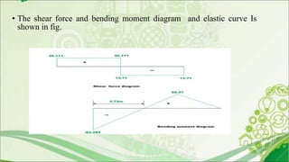
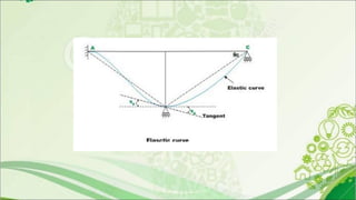
1. The document discusses the slope deflection method of structural analysis, which uses displacements as unknowns rather than forces.
2. The method is based on assumptions that joints are rigid and axial/shear distortions are negligible.
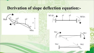
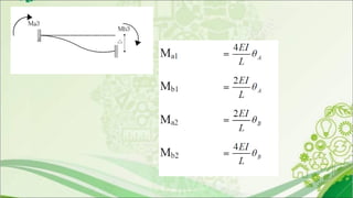
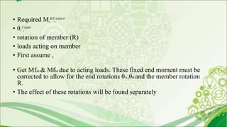
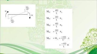
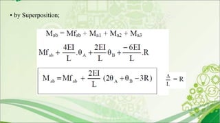
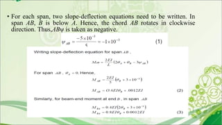
3. Derivation of the slope deflection equations involves determining fixed end moments and correcting for end rotations and member rotation from applied loads.
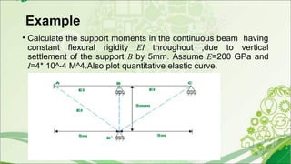
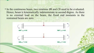
4. An example problem is presented to calculate support moments in a continuous beam due to vertical settlement of one support, by setting up and solving slope deflection equations.


![MODULE-3.1[full].pdf](https://cdn.slidesharecdn.com/ss_thumbnails/module-3-220914062152-19974272-thumbnail.jpg?width=640&height=640&fit=bounds)


