Download as PDF, PPTX
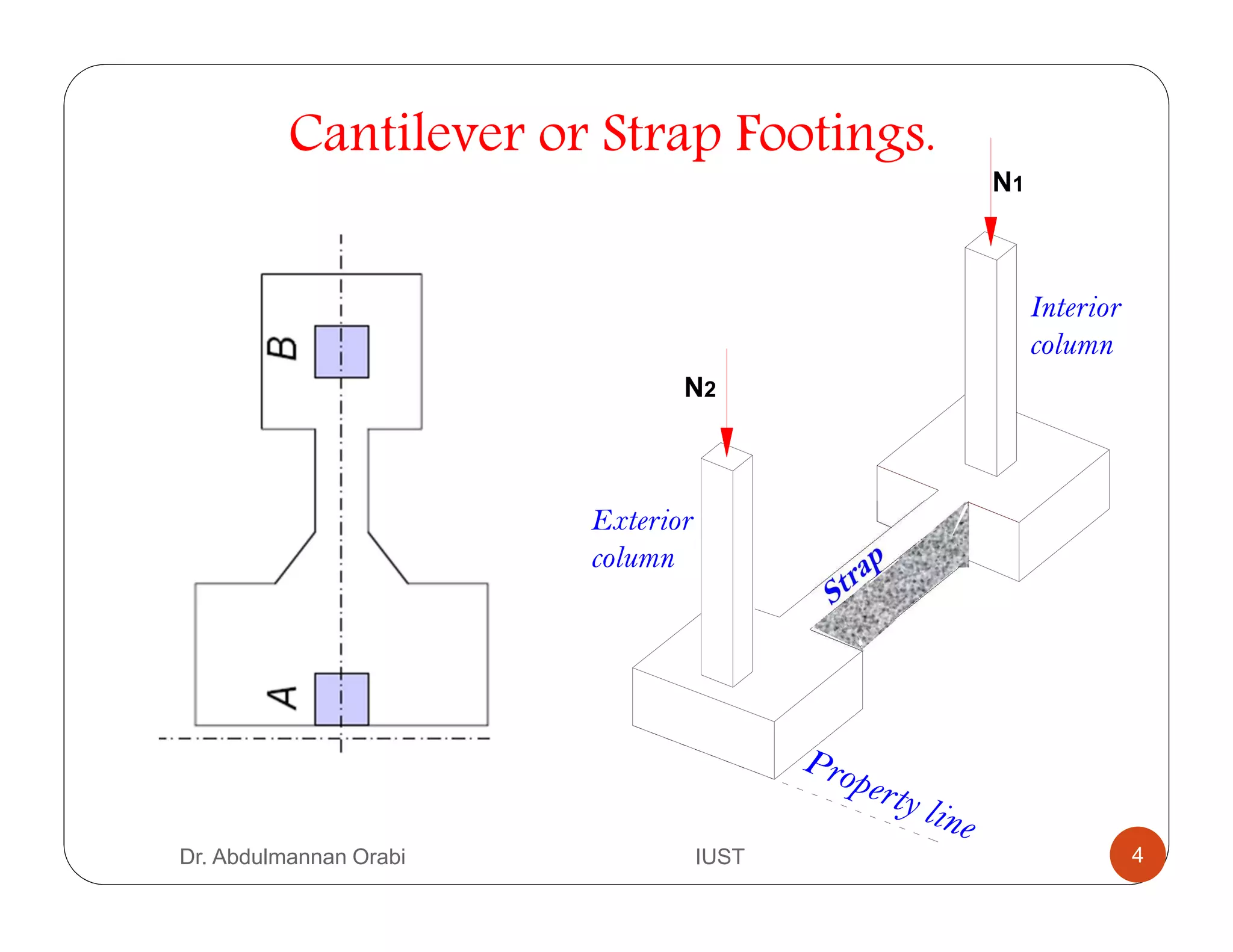
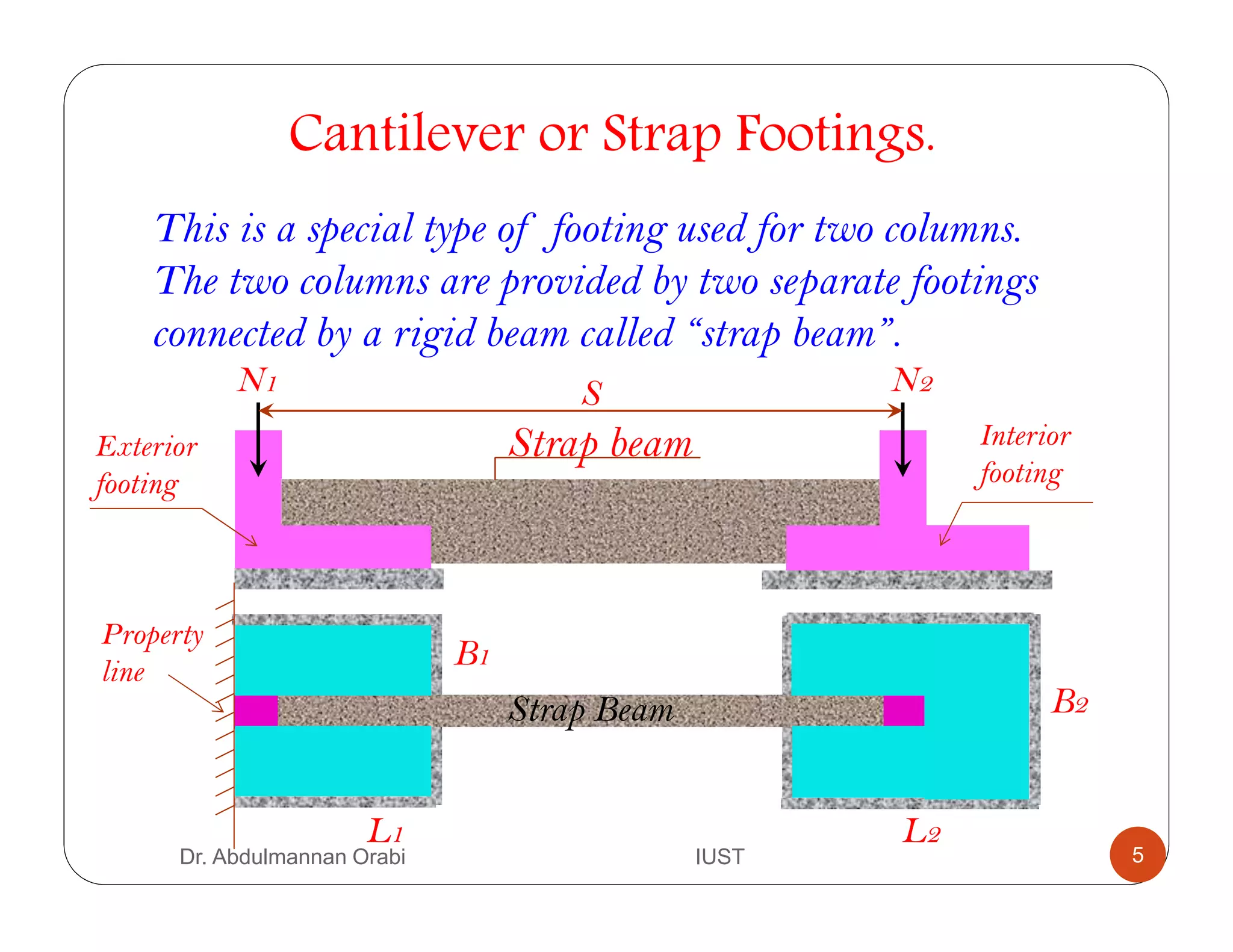
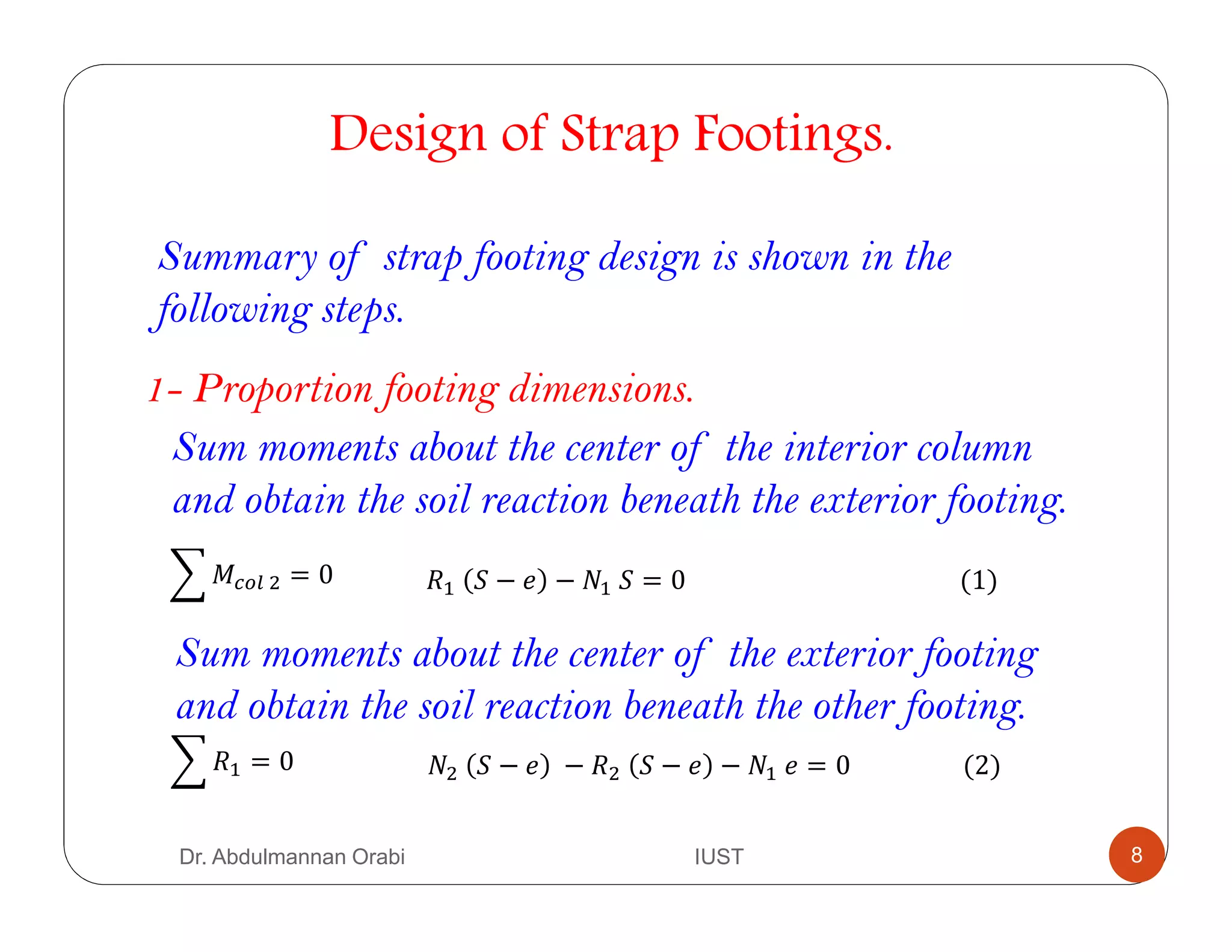
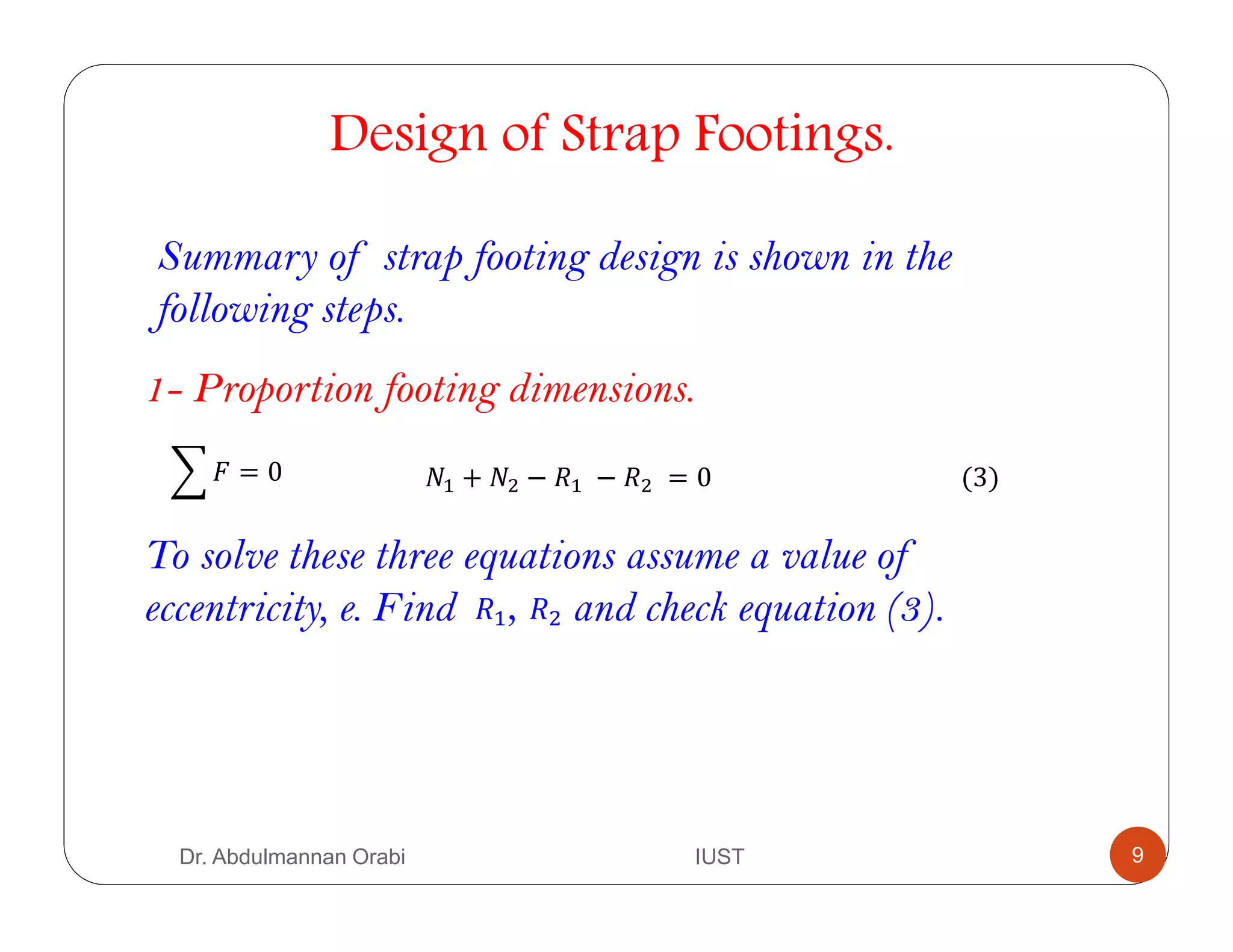
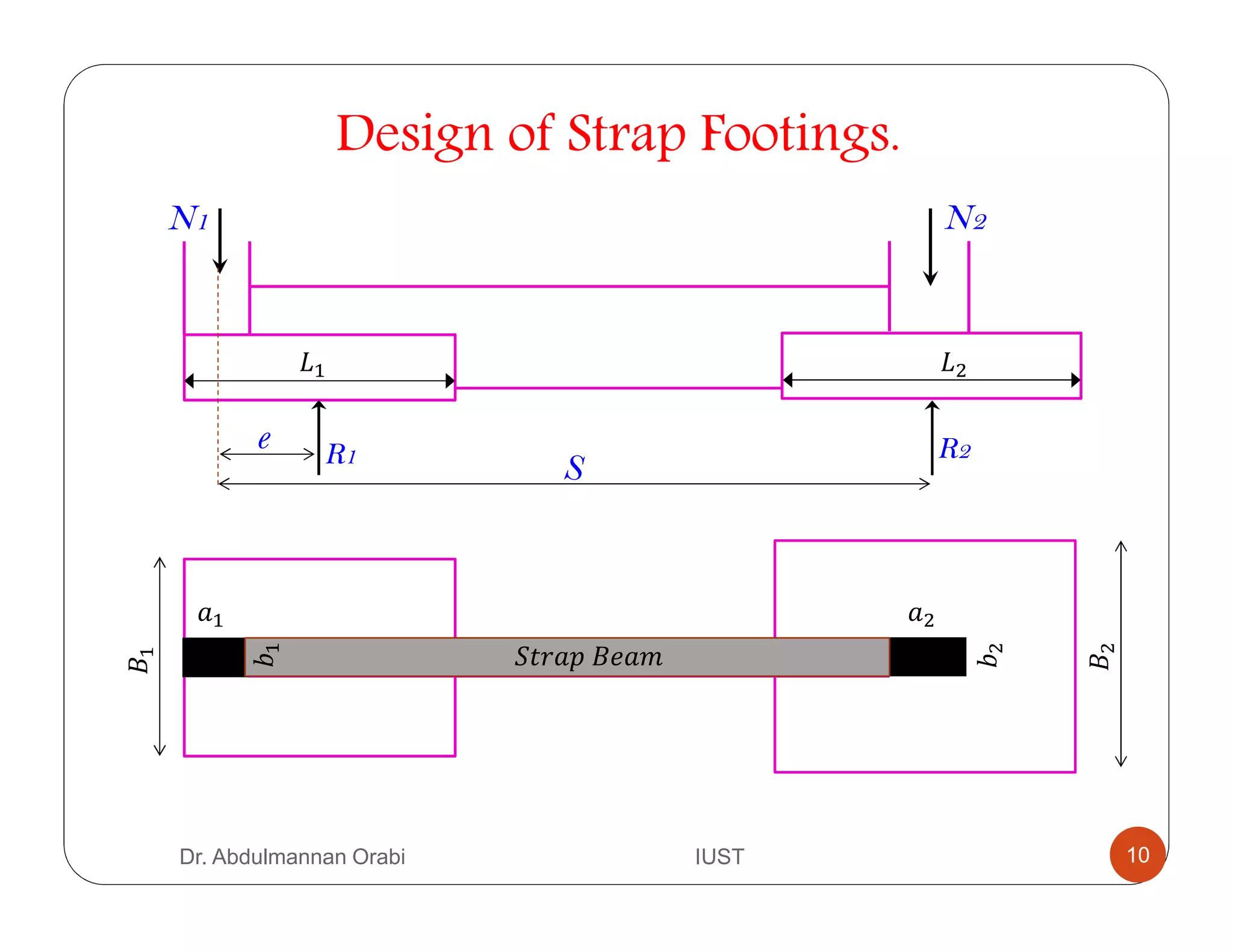
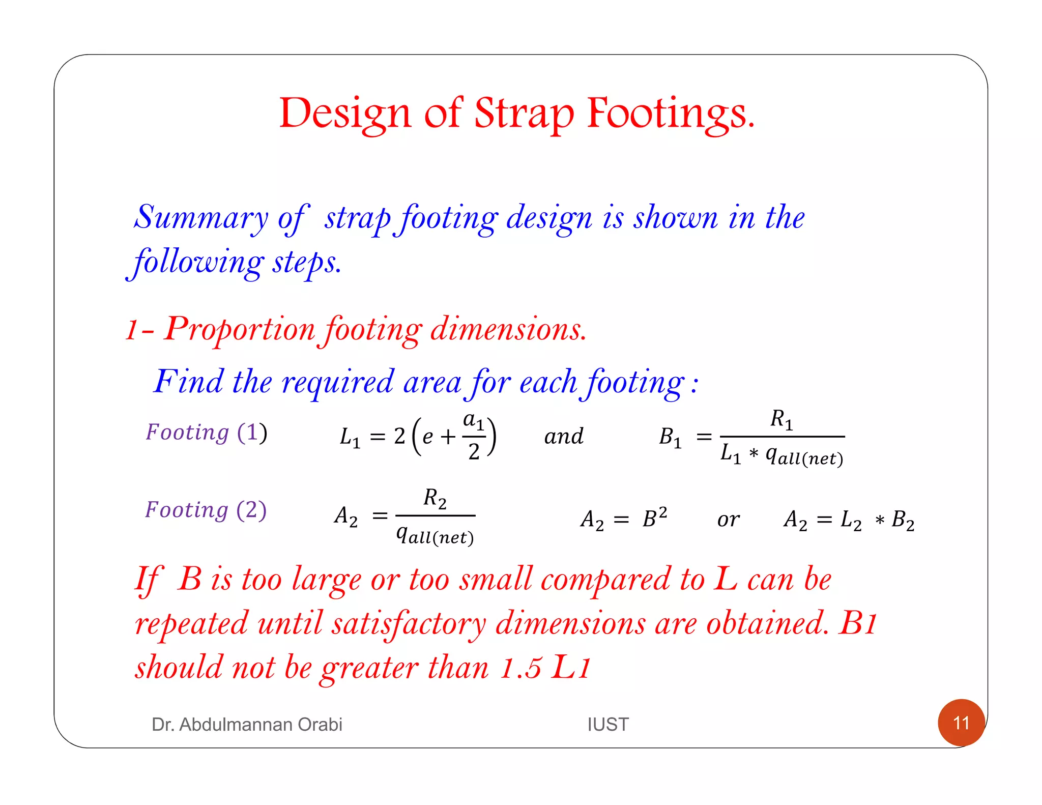
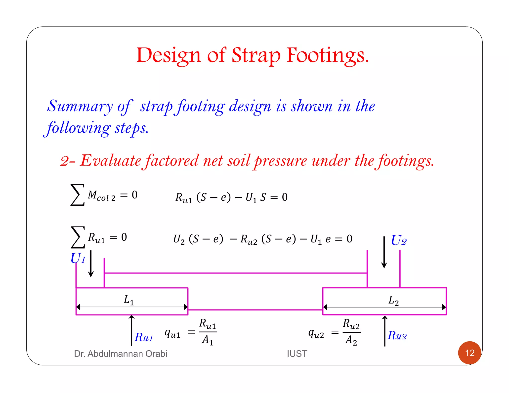
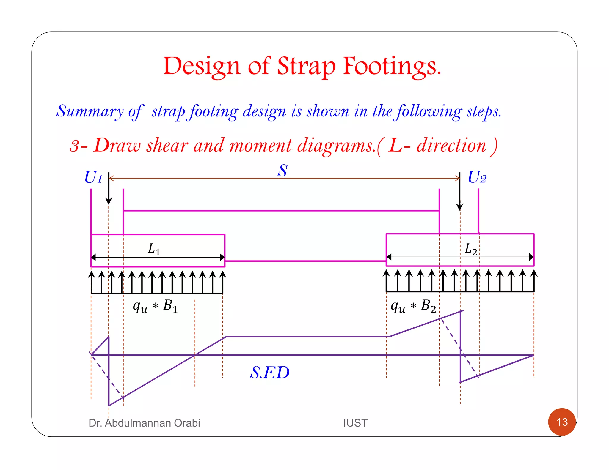
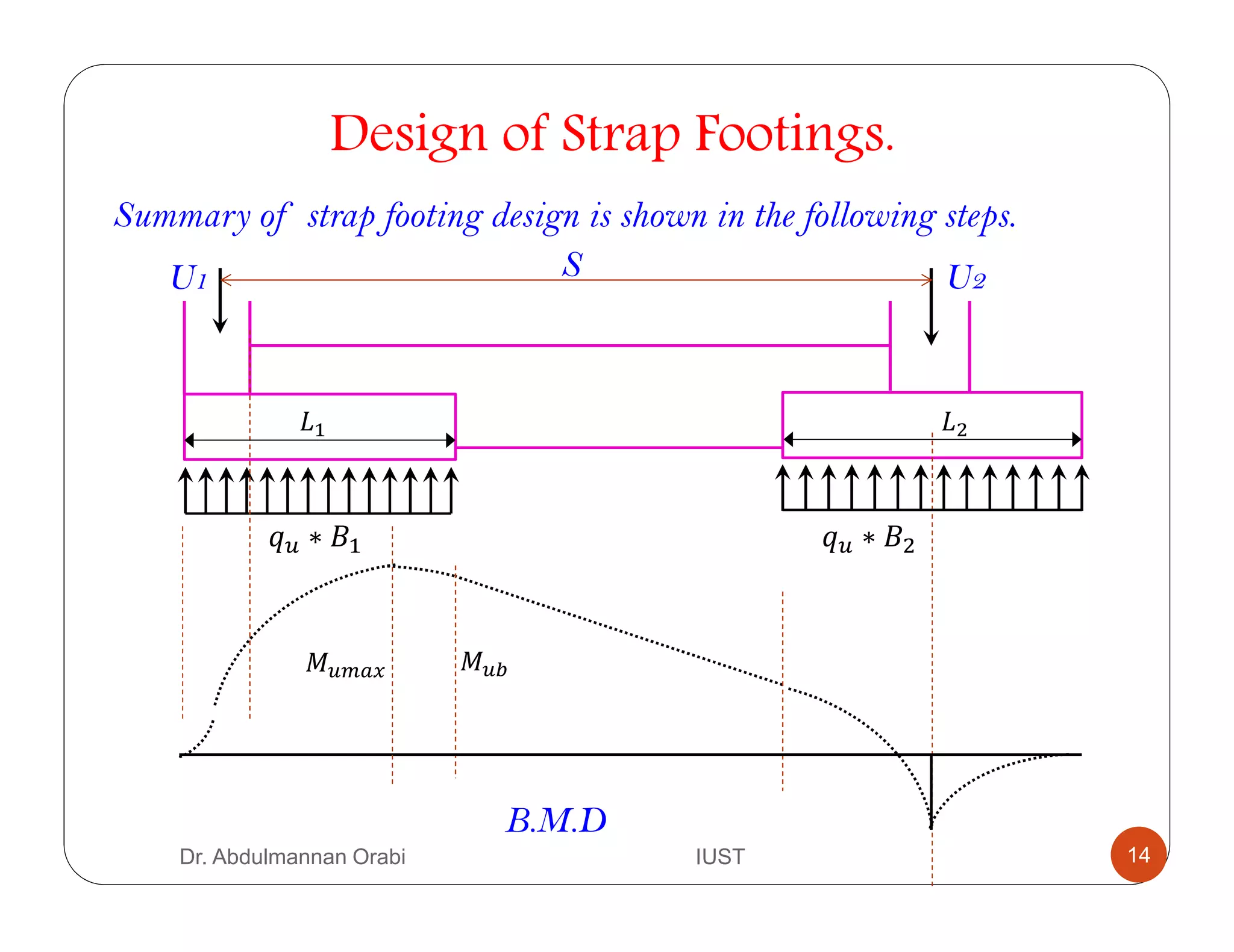
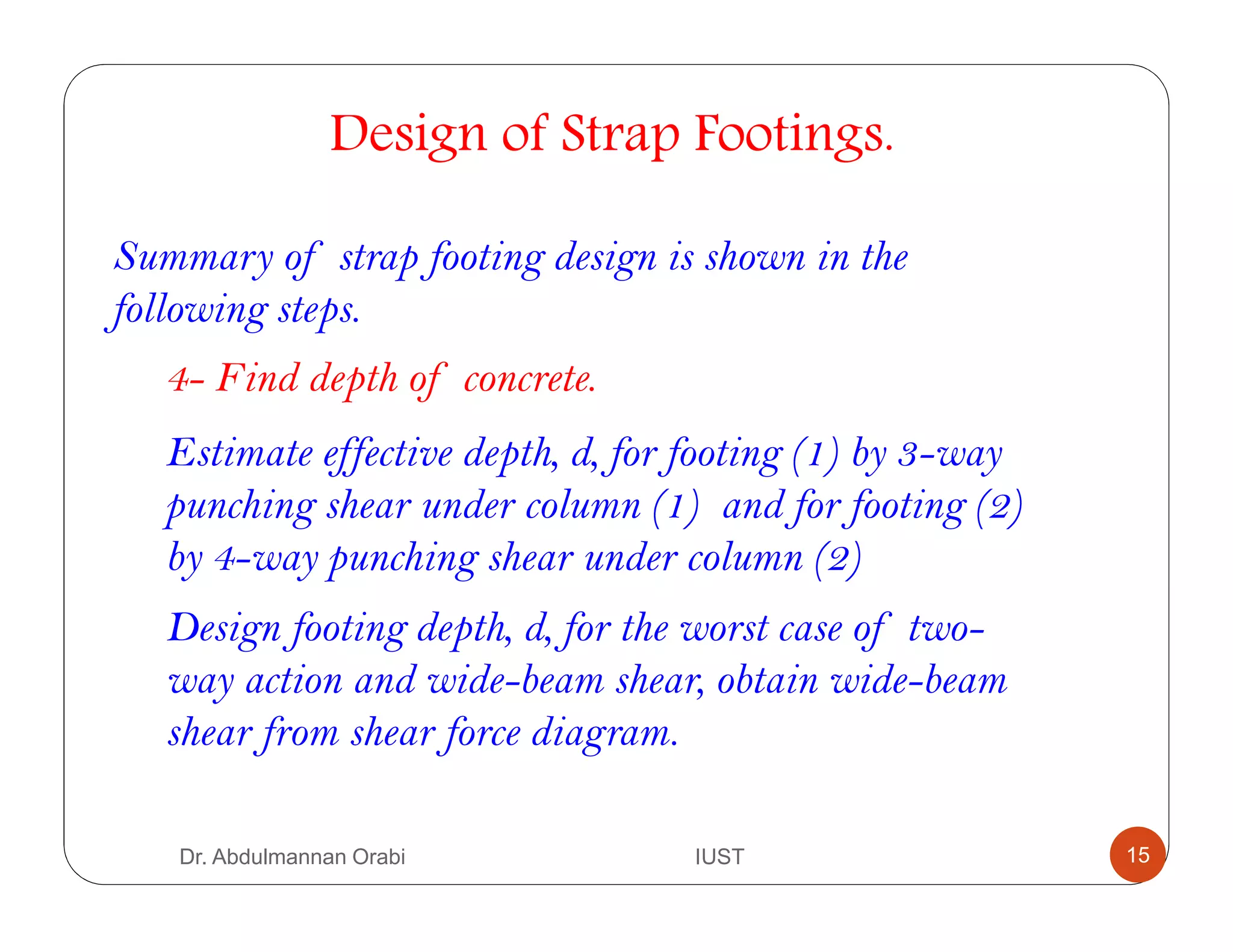
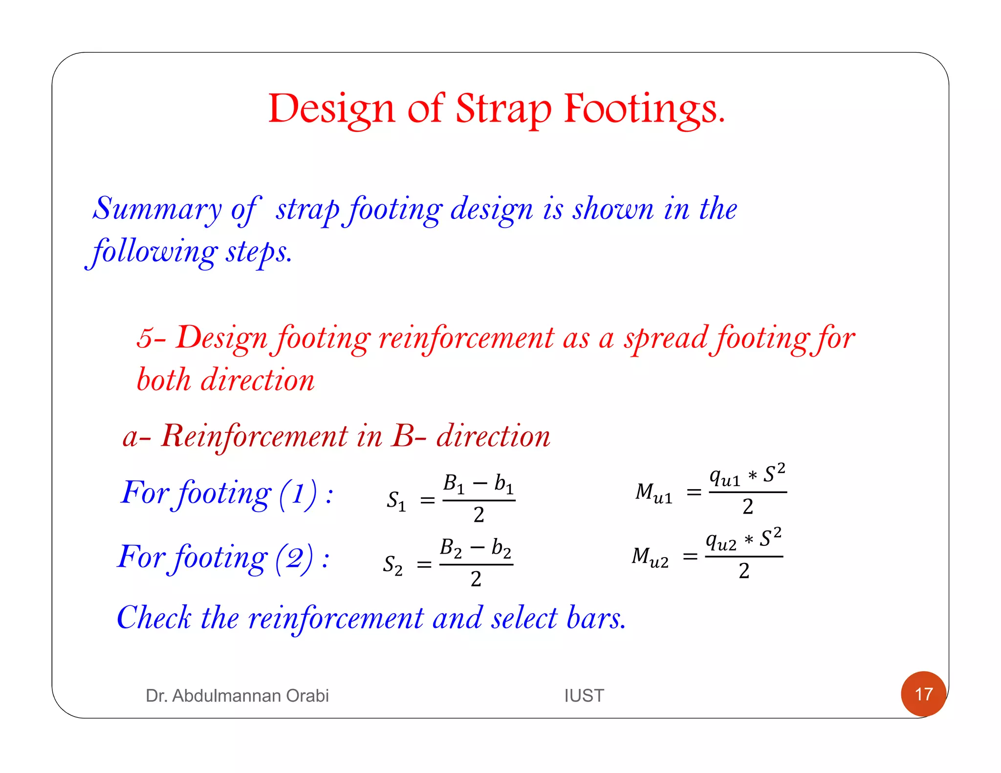
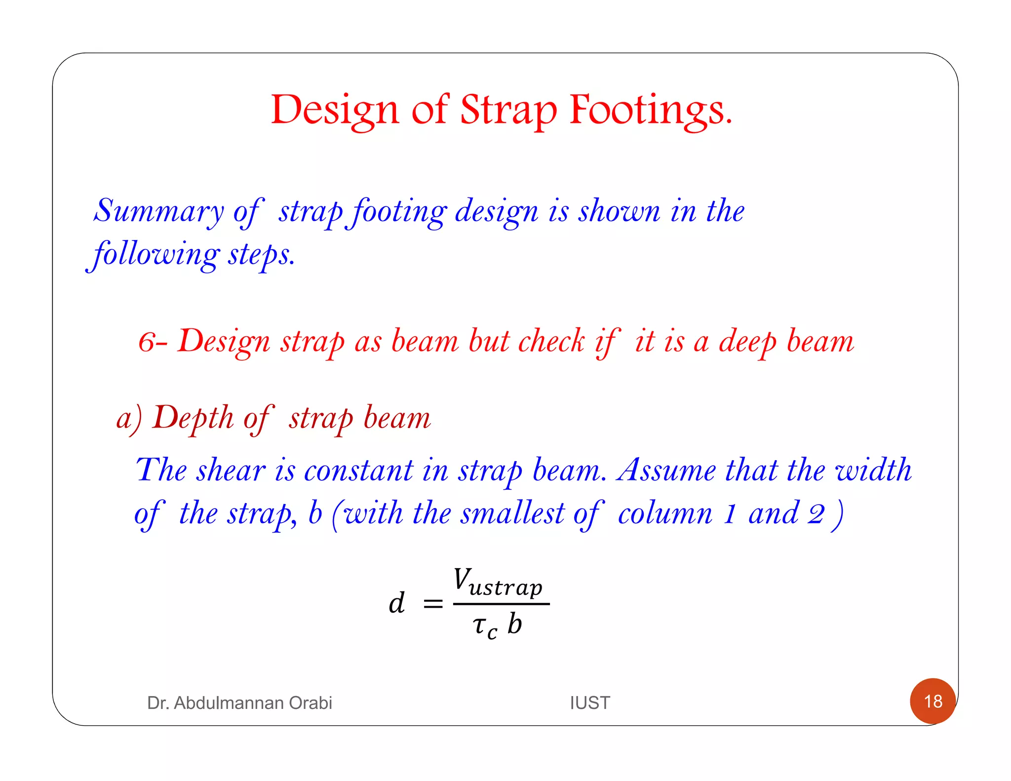
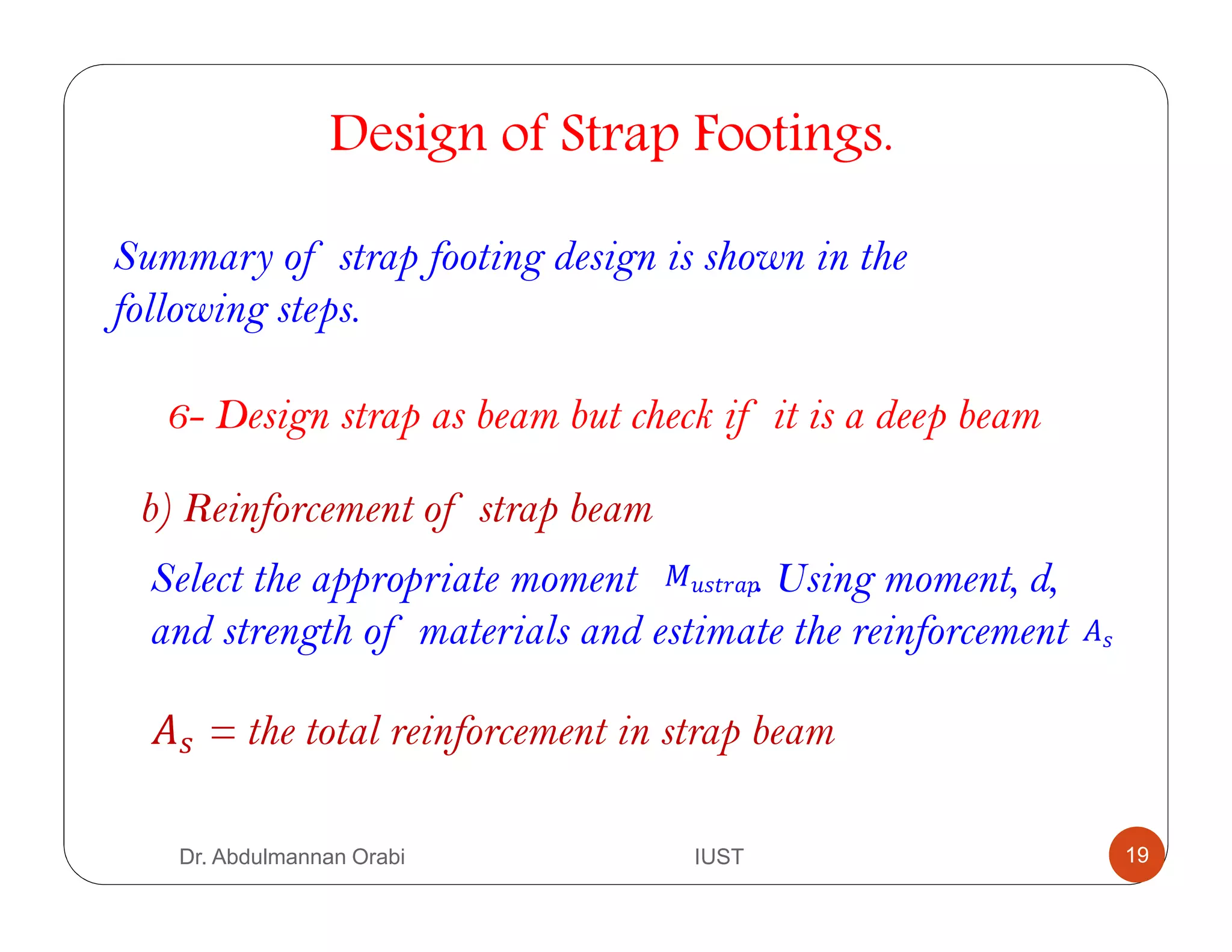
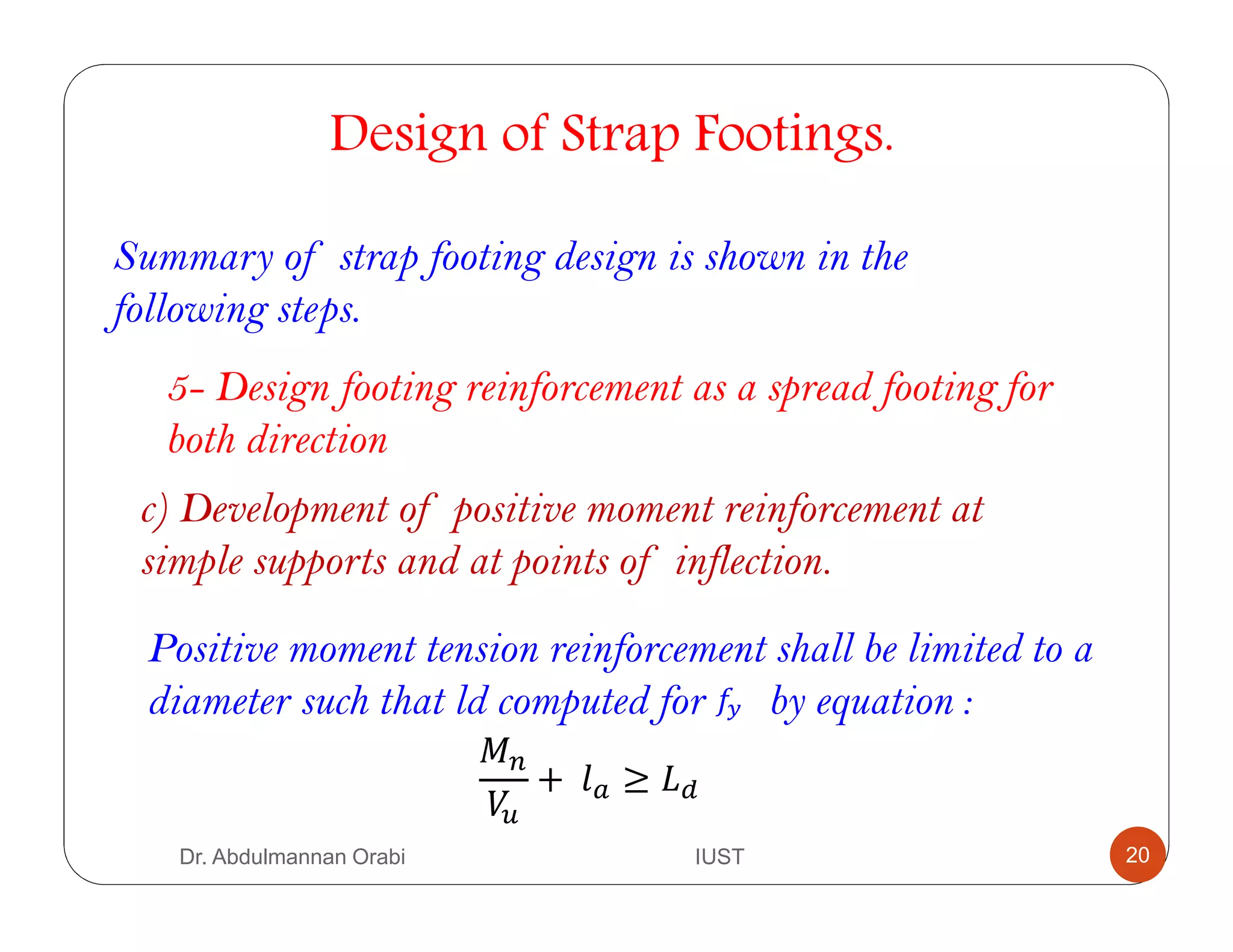
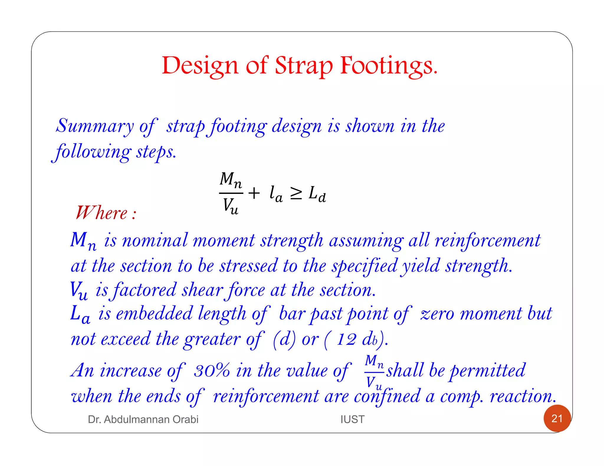
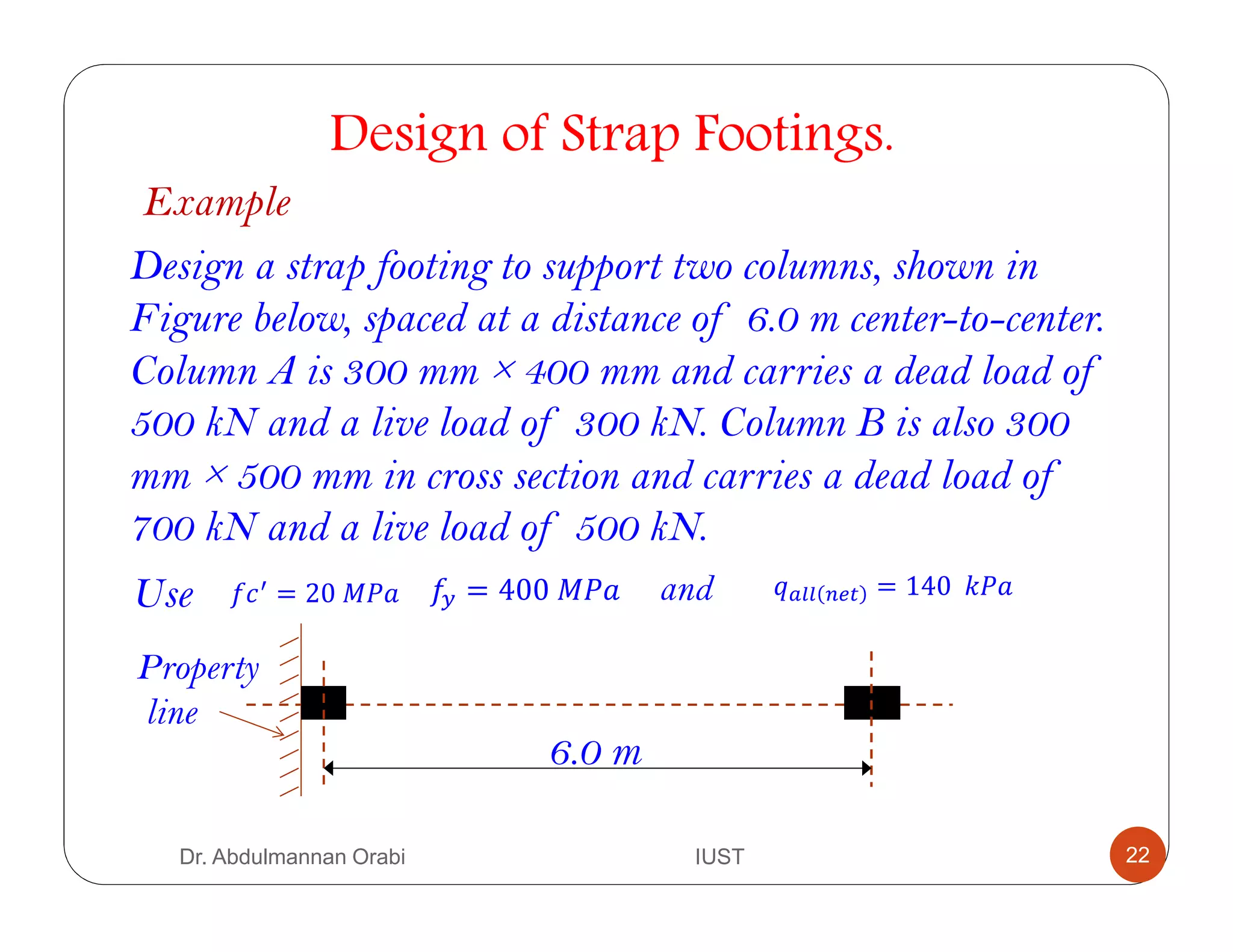

This document provides information about the design of strap footings. It begins with an overview of strap footings, noting they are used to connect an eccentrically loaded column footing to an interior column. The strap transmits moment caused by eccentricity to the interior footing to generate uniform soil pressure beneath both footings. It then outlines the basic considerations for strap footing design: 1) the strap must be rigid, 2) footings should have equal soil pressures to avoid differential settlement, and 3) the strap should be out of contact with soil to avoid soil reactions. Finally, it provides the step-by-step process for designing a strap footing, including proportioning footing dimensions, evaluating soil pressures, designing reinforcement,


